2006 MITSUBISHI COLT Alternator FR Terminal System
[x] Cancel search: Alternator FR Terminal SystemPage 97 of 364
GENERAL INFORMATION
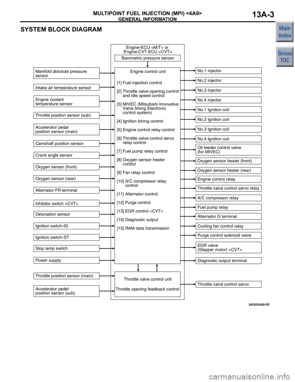
MULTIPOINT FUEL INJECTION (MPI) <4A9>13A-3
SYSTEM BLOCK DIAGRAM
AK600486
Barometric pressure sensorThrottle valve control servo
Manifold absolute pressure
sensor
Engine coolant
temperature sensor
No.1 injector
No.2 injector
No.3 injector
No.4 injector
No.1 Ignition coil
No.2 Ignition coil
No.3 Ignition coil
No.4 Ignition coil
Engine control relay
Throttle valve control servo relay
A/C compressor relay
Fuel pump relay
Alternator G terminal
Cooling fan control relay
Purge control solenoid valve
Diagnostic output terminal
Intake air temperature sensor
Accelerator pedal
position sensor (main) Throttle position sensor (sub)
Camshaft position sensor
Crank angle sensor
Oxygen sensor (front)
Oxygen sensor (rear)
Alternator FR terminal
Inhibitor switch
Detonation sensor
Ignition switch-IG
Ignition switch-ST
Stop lamp switch
Power supply
Accelerator pedel
position sensor (sub) Throttle position sensor (main)
Throttle valve control unitEngine control unit
Engine-ECU
Engine-CVT-ECU
Throttle opening feedback control Oxygen sensor heater (front)
Oxygen sensor heater (rear)
[1] Fuel injection control
[2] Throttle valve opening control
and idle speed control
[3] MIVEC (Mitsubishi Innovative
Valve timing Electronic
control system)
[4] Ignition timing control
[5] Engine control relay control
[6] Throttle valve control servo
relay control
[7] Fuel pump relay control
[8] Oxygen sensor heater
control
[9] Fan relay control
[10] A/C compressor relay
control
[11] Alternator control
[12] Purge control
[13] EGR control
[14] Diagnostic output
[15] RAM data transmission
Oil feeder control valve
(for MIVEC)
EGR valve
(Stepper motor)
AB
Page 98 of 364

GENERAL INFORMATION
MULTIPOINT FUEL INJECTION (MPI) <4A9>13A-4
CONTROL SYSTEM DIAGRAM
AK600525
1 Oxygen sensor
(front)4 Intake air temperature
sensor
3 Manifold absolute
presssure sensor
2 Oxygen sensor (rear) 3 Throttle valve control
servo
10 Throttle position sensor
(main)
2 Purge control
solenoid valve
8 Engine coolant
temperature sensor
9 Detonation sensor
7 Crank angle sensor
6 Camshaft position sensor
4 Oil feeder control valve
1 Injector
AB
M
1 Oxygen sensor (front)
2 Oxygen sensor (rear)
3 Manifold absolute
presssure sensor
4 Intake air temperature
sensor
5 Throttle position
sensor
(sub)
6 Camshaft position
sensor
7 Crank angle sensor
8 Engine coolant
temperature sensor
9 Detonation sensor
10 Throttle position
sensor (main) 1 Injector
2 Purge control
solenoid valve
3 Throttle valve control
servo
4 Oil feeder control
valve
Power supply
Ignition switch-IG
Ignition switch-ST
Accelerator pedal
position sensor
(main)
Accelerator pedal
position sensor
(sub)
Alternator FR
terminal
Stop lamp switchEngine-ECUEngine control relay
Fuel pump relay
A/C compressor relay
Throttle valve
control servo relay
Ignition coil
Cooling fan
control relay
Diagnosis output
Alternator G terminal
Oxygen sensor heater
(front)
Oxygen sensor heater
(rear)
Canister Air
inlet
Catalytic converter From fuel
pump
5 Throttle position sensor
(sub)
Barometric
pressure
sensor
Page 110 of 364

DIAGNOSIS SYSTEM
MULTIPOINT FUEL INJECTION (MPI) <4A9>13A-16
P0606Microcomputer malfunctionAbnormality in engine-ECU
or engine-CVT-ECU
P0622Alternator FR terminal systemOpen circuit or short-circuit in
system-related circuits−
P0638*Throttle valve control servo circuit
range/performance problemAbnormal throttle valve control
servoON
P0642*Throttle position sensor power
supplyAbnormality in engine-ECU
or engine-CVT-ECU
P0657*Throttle valve control servo relay
circuit malfunctionOpen circuit or short-circuit in
sensor-related circuitsON
P1021Oil feeder control valve systemOpen circuit or short-circuit in
solenoid valve-related circuitsON
P1602*Communication malfunction
(between engine-ECU
engine-CVT-ECU
processor and system LSI)Abnormality in engine-ECU
or engine-CVT-ECU
P1603*Battery backup circuit malfunctionOpen circuit or short-circuit in
system-related circuitsON
P2100*Throttle valve control servo circuit
(open)Open circuit in throttle valve control
servo-related circuitON
P2101*Throttle valve control servo
magneto malfunctionShort-circuit in system-related
circuitsON
P2108*Throttle valve control servo
processor malfunctionAbnormality in engine-ECU
or engine-CVT-ECU
P2122*Accelerator pedal position sensor
(main) circuit low inputOpen circuit or short-circuit in
sensor-related circuitsON
P2123*Accelerator pedal position sensor
(main) circuit high inputOpen circuit in sensor-related
circuitsON
P2127*Accelerator pedal position sensor
(sub) circuit low inputOpen circuit or short-circuit in
sensor-related circuitsON
P2128*Accelerator pedal position sensor
(sub) circuit high inputOpen circuit in sensor-related
circuitsON
P2135*Throttle position sensor (main and
sub) range/performance problemAbnormal sensor outputON
P2138*Accelerator pedal position sensor
(main and sub) range/performance
problemAbnormal sensor outputON
P2226Barometric pressure sensor
systemAbnormality in engine-ECU
or engine-CVT-ECU
U1073Bus offAbnormality in CAN bus line−
U1102ABS-ECU time-outAbnormality in CAN bus line−
U1106EPS-ECU time-outAbnormality in CAN bus line−
U1108Combination meter time-outAbnormality in CAN bus lineON
U 111 0A/C-ECU time-outAbnormality in CAN bus line−
Code No. Diagnosis item Main diagnosis contents Engine
warning lamp
Page 113 of 364

DIAGNOSIS SYSTEM
MULTIPOINT FUEL INJECTION (MPI) <4A9>13A-19
Engine-ECU
•Items useful for grasping the engine control con-
dition by the engine-ECU
engine-CVT-ECU
monitor item section.
•Values of these monitor items vary greatly
depending on marginal difference of measure
-
ment conditions, difference of the environment,
aged deterioration of vehicles and so on, and it is
difficult to show the precise specification values.
Therefore, check conditi ons, display range and
movement of values are described.
Item No.Inspection itemDisplay range, numerical value
5AAir-fuel ratio learning value of B zone (Low
speed load)−25 to 25%
5BIdle speed control position learned value−128 to 127STEP
5CIdle speed control position learned value (A/C
load)−128 to 127STEP
6AKnock retardRetards in response to accelerator opening
6BLearned knock retard0 − 100%
6CTarget idle speedChanges in response to engine coolant
temperature
9BAir-fuel ratio learning value of A zone (Low
load)−25 to 25%
9DAir-fuel ratio feedback integration−25 to 25%
B2Alternator G terminal dutyIncreases
B3Purge control solenoid valve duty0 − 100%
81*Long-term fuel compensation−25 to 25%
82*Short-term fuel compensation−25 to 25%
87*Calculation load value0 − 100%
88*Fuel control conditionChanges depending on driving condition
NOTE: *: This item is not displayed when the data list in check mode is selected.
Page 117 of 364
![MITSUBISHI COLT 2006 Service Repair Manual
GENERAL INFORMATION
MULTIPOINT FUEL INJECTION (MPI) <4G1>13B-3
SYSTEM BLOCK DIAGRAM
AK600528
Barometric pressure sensorEngine control unitEngine-ECU
[1] Fuel injection control
[2] Throttle valve open](/manual-img/19/57093/w960_57093-116.png "MITSUBISHI COLT 2006 Service Repair Manual
GENERAL INFORMATION
MULTIPOINT FUEL INJECTION (MPI) <4G1>13B-3
SYSTEM BLOCK DIAGRAM
AK600528
Barometric pressure sensorEngine control unitEngine-ECU
[1] Fuel injection control
[2] Throttle valve open")
GENERAL INFORMATION
MULTIPOINT FUEL INJECTION (MPI) <4G1>13B-3
SYSTEM BLOCK DIAGRAM
AK600528
Barometric pressure sensorEngine control unitEngine-ECU
[1] Fuel injection control
[2] Throttle valve opening control
and idle speed control
[3] MIVEC (Mitsubishi Innovative
Valve timing Electronic
control system)
[4] Ignition timing control
[5] Engine control relay control
[6] Throttle valve control servo
relay control
[7] Fuel pump relay control
[8] Oxygen sensor (front) heater
control
[9] Oxygen sensor (rear) heater
control
[10] Fuel pressure control
[11] Waste gate control
[12] Fan relay control
[13] A/C compressor relay
control
[14] Alternator control
[15] Purge control
[16] Diagnostic output
[17] RAM data transmission Throttle valve control unit
Throttle opening feedback control
Engine coolant
temperature sensor Intake air temperature sensor Air flow sensor
Accelerator pedal
position sensor (main) Throttle position sensor (sub)
Camshaft position sensor
Crank angle sensor
Oxygen sensor (front)
Oxygen sensor (rear)
Alternator FR terminal
Clutch switch
Detonation sensor
Ignition switch-IG
Ignition switch-ST
Stop lamp switch
Power supply
Throttle position sensor (main)
Accelerator pedel
position sensor (sub)
Throttle valve control servo No.1 injector
No.2 injector
No.3 injector
No.4 injector
No.1 Ignition coil
No.2 Ignition coil
No.3 Ignition coil
No.4 Ignition coil
Engine control relay
Throttle valve control servo relay
Waste gate solenoid valve
A/C compressor relay
Fuel pump relay
Alternator G terminal
Cooling fan control relay (Hi, Lo)
Purge control solenoid valve
Diagnostic output terminal
Oxygen sensor (front) heater
Oxygen sensor (rear) heater Oil feeder control valve
(for MIVEC)
Fuel pressure control
solenoid valve
AB
Page 118 of 364

GENERAL INFORMATION
MULTIPOINT FUEL INJECTION (MPI) <4G1>13B-4
CONTROL SYSTEM DIAGRAM
AK600529AB
6 Oil feeder control valve
1 Oxygen sensor
(front)
8 Engine coolant
temperature sensor
3
Throttle valve control servo
10
Throttle position sensor (main)
5 Throttle position sensor (sub)
2 Purge control
solenoid valve
4 Fuel pressure
solenoid valve
7 Crank angle sensor
9
Detonation sensor
4
Intake air
temperature
sensor
3
Air flow sensor
Waste gate
actuator Canister
Check
valve Air by-pass valve
Fuel pressure regulatorFrom
fuel pump
To fuel
tank
Catalytic converter
Catalytic
converter
Air
inlet
Oxygen sensor (front)
Oxygen sensor (rear)
Air flow sensor
Intake air temperature
sensor
Throttle position
sensor
(sub)
Camshaft position
sensor
Crank angle sensor
Engine coolant
temperature sensor
Detonation sensor
Throttle position
sensor (main) Power supply
Ignition switch-IG
Ignition switch-ST
Accelerator pedal
position sensor
(main)
Accelerator pedal
position sensor
(sub)
Alternator FR
terminal
Stop lamp switch
Clutch switchEngine-
ECUEngine control relay
Fuel pump relay
A/C compressor relay
Throttle valve
control servo relay
Ignition coil
Cooling fan
control relay
(Hi, Lo)
Diagnosis output
Alternator G terminal
Oxygen sensor (front)
heater
Oxygen sensor (rear)
heater
Barometric
pressure
sensor
1 Injector
5 Waste gate
solenoid valve
2 Oxygen sensor
(rear)
6 Camshaft position sensor
1
2
3
4
5
6
7
8
9
10 Injector
Purge control
solenoid valve
Throttle valve
control servo
Fuel pressure
solenoid valve
Waste gate
solenoid valve
Oil feeder control
valve
1
2
3
4
5
6
Page 130 of 364

DIAGNOSIS SYSTEM
MULTIPOINT FUEL INJECTION (MPI) <4G1>13B-16
P0500Vehicle speed sensor systemOpen circuit or short-circuit in
sensor-related circuitsON
P0513Immobilizer malfunctionOpen circuit or short-circuit in
sensor-related circuits−
P0603EEPROM malfunctionAbnormality in engine-ECU−
P0606Engine-ECU main processor
malfunctionAbnormality in engine-ECUON
P0622Alternator FR terminal systemOpen circuit or short-circuit in
system-related circuits−
P0638Throttle valve control servo circuit
range/performance problemAbnormal throttle valve control
servoON
P0642Throttle position sensor power
supply malfunctionOpen circuit or short-circuit in
sensor-related circuitsON
P0657Throttle valve control servo relay
circuit malfunctionOpen circuit or short-circuit in
sensor-related circuitsON
P1021Oil feeder control valve systemOpen circuit and short-circuit in
solenoid valve-related circuits−
P1231Trustful check active stability
control (ASC)ABS/ASC-ECU−
P1233Trustful check throttle position
sensor (main)Abnormality in throttle position
sensor (main)ON
P1234Trustful check throttle position
sensor (sub)Abnormality in throttle position
sensor (sub)ON
P1235Trustful check air flow sensorAbnormality in air flow sensorON
P1236A/D converter systemAbnormality in engine-ECUON
P1237Trustful check accelerator pedal
position sensorAbnormality in accelerator pedal
position sensorON
P1238Air flow sensor trustful for torque
monitoringAbnormality in engine-ECUON
P1239Trustful check engine speedAbnormality in engine-ECUON
P1240Trustful check ignition angleAbnormality in ABS/ASC-ECU−
P1241Torque monitoringAbnormality in engine-ECUON
P1602Communication malfunction
(between engine-ECU main
processor and system LSI)Abnormality in engine-ECUON
P1603Battery back-up circuit malfunctionOpen circuit or short-circuit in
system-related circuitsON
P2100Throttle valve control servo circuit
(open)Open circuit in throttle valve control
servo-related circuitON
P2101Throttle valve control servo
magneto malfunctionShort-circuit in system-related
circuitsON
P2108Throttle valve control servo
processor malfunctionAbnormality in engine-CVT-ECUON
Code No. Diagnosis item Main diagnosis contents Engine
warning lamp
Page 133 of 364

DIAGNOSIS SYSTEM
MULTIPOINT FUEL INJECTION (MPI) <4G1>13B-19
Engine-ECU Monitor Item
•Items useful for grasping the engine control condition by the engine-ECU are provided in this monitor item
section.
•Values of these monitor items vary greatly depending on marginal difference of measurement conditions,
difference of the environment, aged deterioration of vehicl es and so on, and it is difficult to show the pre
-
cise specification values. Therefore, check conditions, display range and movement of values are
described.
Item No.Inspection itemDisplay range, numerical value
5AAir-fuel ratio learning value of B zone (Low
speed load)−25 to 25%
5BIdle speed control position learned value−128 to 127STEP
5CIdle speed control position learned value (A/C
load)−128 to 127STEP
6AKnock retardRetards in response to accelerator opening
6BLearned knock retard0 − 100%
6CTarget Idle speedChanges in response to engine coolant
temperature
9BAir-fuel ratio learning value of A zone (Low
speed load)−25 to 25%
9DAir-fuel ratio feedback integration−25 to 25%
B1Waste gate solenoid valve duty0 − 100%
B2Alternator G terminal dutyIncreases
B3Purge control solenoid valve duty0 − 100%
81*Long-term fuel compensation−25 to 25%
82*Short-term fuel compensation−25 to 25%
87*Calculation load value0 − 100%
88*Fuel control conditionChanges depending on driving condition
NOTE: *: This item is not displayed when the data list in check mode is selected.