Page 217 of 364
MAJOR SPECIFICATIONS
GENERAL00-32
M2000030000848
AC401657AB
1
2 34
658
97
ItemZ23AZ27A
XNMHR8XNXHR8XNGFR8
LSVR-XRALLIART Version-R
Vehicle dimensions
mmFront track11,4601,465
Overall width21,6801,695
Front overhang3790815
Wheel base42,500
Rear overhang5595610
Overall length63,8853,925
Ground clearance
(unladen)7150
Overall height (unladen)81,550
Rear track91,4451,450
Vehicle weight kgKerb weight1,0201,0351,130
Max. gross vehicle weight1,4601,470
Max. axle weight rating-front780850
Max. axle weight rating-rear700640
Seating capacity54
EngineModel code4A914G15 (with intercooler,
turbocharger)
Total displacement mL1,4991,468
TransmissionModel codeF5MGAF5MGB
Ty p eFloor shift M/T
Fuel systemFuel supply systemMPI
Page 219 of 364

GENERAL INFORMATION
POWER PLANT MOUNT32-2
GENERAL INFORMATION
M2320000100663
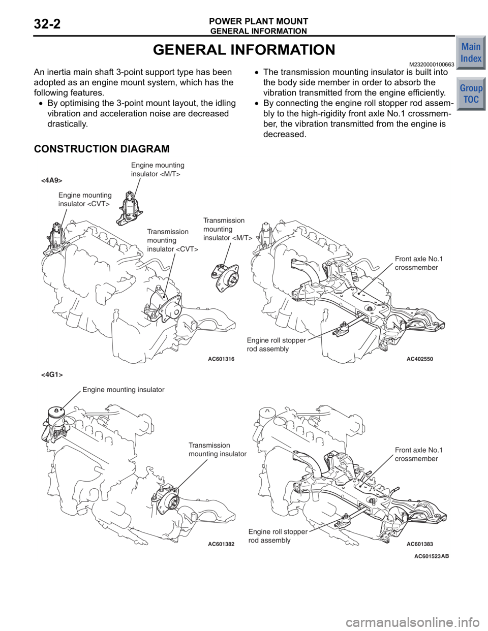
An inertia main shaft 3-point support type has been
adopted as an engine mount system, which has the
following features.
•By optimising the 3-point mount layout, the idling
vibration and acceleration noise are decreased
drastically.
•The transmission mounting insulator is built into
the body side member in order to absorb the
vibration transmitted from the engine efficiently.
•By connecting the engine roll stopper rod assem-
bly to the high-rigidity front axle No.1 crossmem-
ber, the vibration transmitted from the engine is
decreased.
CONSTRUCTION DIAGRAM
AC601523
AC402550
AC601316
AC601382AC601383
<4A9>
<4G1>
AB
Engine mounting
insulator Engine mounting insulator Transmission
mounting
insulator
Transmission
mounting insulator Front axle No.1
crossmember
Front axle No.1
crossmember
Engine roll stopper
rod assembly
Engine mounting
insulator
Transmission
mounting
insulator
Engine roll stopper
rod assembly
Page 276 of 364

DIAGNOSTIC FUNCTION
SMART WIRING SYSTEM (SWS)54B-10
NOTE: .
•− shown in the table indicates that the check item for the input of the corresponding signal is not present in
M.U.T.-III.
•*1Checking the input signal by the sound of the buzzer is not possible. Input signal must be checked on
the M.U.T.-III display.
•*2: Buzzer sound during the check is triggered by the input signal from the ignition switch. It is not to check
the presence of the power window switch acceptance permission signal.
•*3: Buzzer sound during the check is triggered by the input signal from the keyless entry transmitter. It is
not to check the presence of the multimode keyless entry input signal.
With windshield intermittent
wiper control
*1
The display alters according to the presence of the
equipment ("EQUIP" or "NONE").EQUIP
Specification switching
terminal
*1
The display alters according to the transmission type
("A/T" or "M/T").M/T or A/T
Diagnosis connector*1Diagnosis control line: EarthedON
Diagnosis control line: Not earthedOFF
Input signal Condition for sounding buzzer Display on
M.U.T.-III (when
SWS monitor is
used)
Page 336 of 364

MAIN INDEX
00Genera l. . . . . . . . . . . . . . . . . . . . . . . .
11Engin e. . . . . . . . . . . . . . . . . . . . . . . . .
12Engine Lubricatio n . . . . . . . . . . . . . .
13Fuel. . . . . . . . . . . . . . . . . . . . . . . . . . .
14Engine Coolin g . . . . . . . . . . . . . . . . .
15Intake and Exhaus t . . . . . . . . . . . . . .
16Engine Electrica l . . . . . . . . . . . . . . . .
17E ngine an d Emissi on Contro l. . . . . .
21Clutc h . . . . . . . . . . . . . . . . . . . . . . . . .
22Manual Transmissio n . . . . . . . . . . . .
23. . . . . . . . . . . . . . . . . . . . . . . . . . . . . . .
26Front Axl e. . . . . . . . . . . . . . . . . . . . . .
27Rear Axl e . . . . . . . . . . . . . . . . . . . . . .
31Wheel and Tyr e . . . . . . . . . . . . . . . . .
32Power Plant Moun t . . . . . . . . . . . . . .
33Front Suspensio n . . . . . . . . . . . . . . .
34Rear Suspensio n. . . . . . . . . . . . . . . .
35Service Brake s. . . . . . . . . . . . . . . . . .
36Parking Brake s. . . . . . . . . . . . . . . . . .
37Steerin g . . . . . . . . . . . . . . . . . . . . . . .
42Bod y . . . . . . . . . . . . . . . . . . . . . . . . . .
51Exterio r. . . . . . . . . . . . . . . . . . . . . . . .
52Genera l. . . . . . . . . . . . . . . . . . . . . . . .
54Chass is Electrica l . . . . . . . . . . . . . . .
55. . . . . . . . . . . . . . . . . . . . . . . . . . . . . . . . . .
COLT
TECHNICAL
INFORMATION MANUAL
FOREWORD
This manual has been prepared as an introduction to
the specifications, features, construction, functions,
etc. of the newly developed COLT.
Please read this manual carefully so that it will be of
assistance for your service activities. Please note the
following service manuals are also available and
should be used in conjunction with this manual.
WORKSHOP MANUAL
CHASSIS GROUP
BODY REPAIR MANUAL
PARTS CATALOGUE
All information, illustra tions and product descriptions
contained in this manual are current as of the time of
publication. We, however, reserve the right to make
changes at any time without prior notice or obligation.
© Mitsubishi Motors Corporation 2006
Interior and Supplemental
Restraint System (SR S) . . . . . . . . . .
Heater, Air Conditioner and
Ventila tio n . . . . . . . . . . . . . . . . . . . . .
Continuously Variable
Transmission (CVT ). . . . . . . . . . . . . .
����
Page 349 of 364
GROUP 23
CONTINUOUSLY VARIABLE
TRANSMISSION (CVT)
CONTENTS
CVT. . . . . . . . . . . . . . . . . . . . . . . . . . .23-2
GENERAL INFORMATION . . . . . . . . . . . . . 23-2
ELECTRONIC CONTROL SYSTEM. . . . . . 23-3
EEPROM. . . . . . . . . . . . . . . . . . . . . . . . . . . 23-3
CONTROLLER AREA NETWORK (CAN)
COMMUNICATION . . . . . . . . . . . . . . . . . . . 23-3
RATIO PATTERN . . . . . . . . . . . . . . . . . . . . 23-3
DIAGNOSIS CLASSIFICA TION TABLE . . . 23-4
ATF WARMER (ATF COOLER) . . . . . . . . . 23-5
TRANSMISSION CONTROL . . . . . . .23-6
GENERAL INFORMATION . . . . . . . . . . . . . 23-6
SELECTOR LEVER ASSEMBLY . . . . . . . . 23-7
CVT ERRONEOUS OPERATION
PREVENTION MECHANISMS . . . . . . . . . . 23-8
Page 350 of 364

CVT
CONTINUOUSLY VARIABLE TRANSMISSION (CVT)23-2
CVT
GENERAL INFORMATIONM2231000100165
The F1C1A transmission is adopted for the CVT.
This transmission is basically the same as conven
-
tional transmission.
The ATF warmer (ATF cooler) is adopted.
SPECIFICATIONS
ItemSpecification
Transmission modelF1C1A
Engine model4A91
Torque converterTy p e3-element, 1-stage, 2-phase type
Lock-upProvided
Stall torque ratio2.0
Transmission typeForward automatic continuously variable (steel belt type),
1st in reverse
Gear ratioForward2.319 − 0.445
Reverse2.588
ClutchA pair of multi-plate system
BrakeA pair of multi-plate system
Manual control systemP-R-N-D-Ds-L (smart shift)
FunctionVariable speed controlYe s
Line pressure controlYe s
Direct engagement controlYe s
N-D/N-R controlYe s
Shift pattern controlYe s
Self-diagnosisYe s
FailsafeYe s
Oil pumpTy p eExternal gear pump
ConfigurationBuilt-in (chain drive)
Control methodElectronic control (INVECS-III)
Transmission oilSpecified lubricantsDIA QUEEN ATF SP III
Quantity L8.1
Page 351 of 364

CVT
CONTINUOUSLY VARIABLE TRANSMISSION (CVT)23-3
ELECTRONIC CONTROL SYSTEM
EEPROM
M2231012000024
Because EEPROM has been used, even if the bat-
tery terminals or control unit connectors are discon-
nected, the necessary learned values are stored in
the engine-CVT-ECU to prevent a loss of shift qual
-
ity. (Initialisation is available by M.U.T.-III).
CONTROLLER AREA NETWORK (CAN)
COMMUNICATION
M2231017000018
CAN* communication has been adopted for commu-
nication with other ECUs in order to decrease the
number of wires and ensure information transmis
-
sion. For CVT control, the engine-CVT-ECU receives
the following signals.
CAN COMMUNICATION INPUT SIGNAL TABLE
Input signalTransmitter ECU
Average vehicle speed signal from drive wheelsABS-ECU
Motor current signalEPS-ECU
EPS warning lamp illumination request signal
Compressor signalMeter and A/C-ECU
NOTE: *: For more information about CAN (Control-
ler Area Network), refer to GROUP 54C P.54C-2.
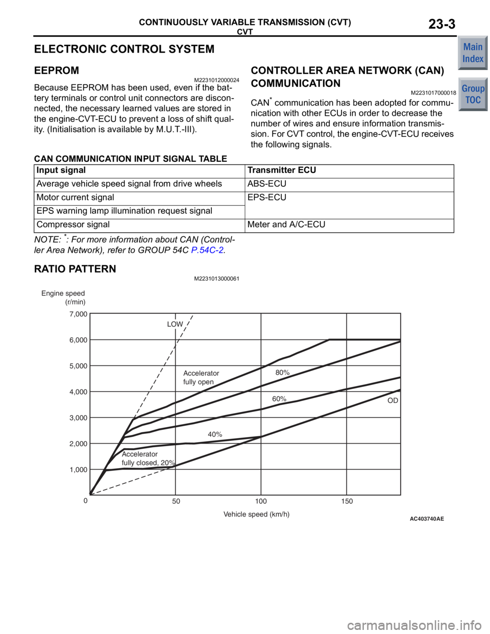
RATIO PATTERN
M2231013000061
AC403740
AE
Engine speed
(r/min)
Vehicle speed (km/h)
0
100 150
50
1,000 2,000 4,000
3,000 5,000
7,000
6,000
OD
LOW
Accelerator
fully closed, 20% 40%
Accelerator
fully open
60%80%
Page 352 of 364

CVT
CONTINUOUSLY VARIABLE TRANSMISSION (CVT)23-4
DIAGNOSIS CLASSIFICATION TABLE
M2231015000056
ItemDiagnosisData listActuator
test
Code No.Trouble symptomsItem No.Display
Crank angle sensor−−01r/min−
CVT fluid temperature sensor15Open circuit08°C−
16Short circuit
Line pressure sensor18Open circuit09MPa−
19Short circuit
Turbine speed sensor22Open circuit02r/min−
Primary speed sensor23Open circuit03r/min−
26System failure
Secondary speed sensor24Open circuit04r/min−
25System failure
Accelerator pedal position sensor (APS)−−06mV−
Primary pressure sensor27Open circuit11MPa−
28Short circuit
Gear ratio−−12Displays the
gear ratio.−
Line pressure control solenoid valve31Open circuit/short
circuit 16%01
Shift control solenoid valve32Open circuit15%02
36Short circuit
Damper clutch control solenoid valve33Open circuit14%03
37Short circuit
Clutch pressure control solenoid valve34Open circuit17%04
38Short circuit
Shift system42System failure−−−
Damper clutch system44System failure10r/min−
45
Clutch system46System failure−−−
48
Inhibitor switch51Open circuit26P/R/N/D/Ds/L−
52Short circuit
Stop lamp switch53Open circuit33ON/OFF−
54Short circuit
Battery voltage−−24V−
CVT control relay56Open circuit25V11
Steel belt system59System failure−−−
Line pressure system57System failure−−−
71
72