Page 194 of 364

TECHNICAL FEATURES
GENERAL00-9
ENGINE
M2000020000579
<4A9>
The newly-developed 4A9 engine has been installed
to realise small-size, light-weight, high-performance,
and better fuel economy with the state-of-the-art
technologies such as the aluminium die-cast cylinder
block, direct attack driven-type DOHC MIVEC, timing
chain-type cam drive, and rear exhaust.
MAJOR SPECIFICATIONS
Item4A91
Total displacement mL1,499
Bore × Stro ke mm75 × 84.8
Compression ratio10.0
Compression chamberPentroof-type
Va l v e t i m i n gIntake openingBTDC 31° − ATDC 19°
Intake closingABDC 21° − ABDC 71°
Exhaust openingBBDC 39°
Exhaust closingATDC 5°
Maximum output kW (PS)/rpm77 (105)/6,000
Maximum torque N⋅m (kg⋅m)/rpm141 (14.4)/4,000
Fuel systemElectronically controlled multipoint fuel injection
Ignition systemElectronic-controlled 4-coil
<4G1>
Based on the 4G1 engine fitted on the existing COLT,
the power performance leading the compact car field
has been secured by Turbocharger.
MAJOR SPECIFICATIONS
Item4G15 (with Intercooler Turbocharger)
Total displacement mL1,468
Bore × Stro ke mm75 × 82.0
Compression ratio9.0
Compression chamberPentroof-type
Va l v e t i m i n gIntake openingBTDC 34° − ATDC 6°
Intake closingABDC 30° − ABDC 70°
Exhaust openingBBDC 50°
Exhaust closingATDC 10°
Maximum output kW (PS)/rpm113 (154)/6,000
Maximum torque N⋅m (kg⋅m)/rpm210 (21.4)/3,500
Fuel systemElectronically controlled multipoint fuel injection
Ignition systemElectronic-controlled 4-coil
Page 196 of 364
TECHNICAL FEATURES
GENERAL00-11
CVT
The F1C1A transmission is adopted for the CVT.
This transmission is basically the same as conven
-
tional transmission.
The ATF warmer (ATF cooler) is adopted.
SPECIFICATIONS
ItemSpecification
Transmission modelF1C1A
Engine model4A91
Torque converterTy p e3-element, 1-stage, 2-phase type
Lock-upProvided
Stall torque ratio2.0
Transmission typeForward automatic continuously variable (steel belt type),
1st in reverse
Gear ratioForward2.319 − 0.445
Reverse2.588
ClutchA pair of multi-plate system
BrakeA pair of multi-plate system
Manual control systemP-R-N-D-Ds-L (smart shift)
FunctionVariable speed controlYe s
Line pressure controlYe s
Direct engagement controlYe s
N-D/N-R controlYe s
Shift pattern controlYe s
Self-diagnosisYe s
FailsafeYe s
Oil pumpTy p eExternal gear pump
ConfigurationBuilt-in (chain drive)
Control methodElectronic control (INVECS-III)
Page 203 of 364

TECHNICAL FEATURES
GENERAL00-18
STEERING
M2000040000140
AC403622
Steering wheel
Steering wheel
Steering column assembly
Torque sensor
Tie-rod end
Yoke-bearing
Crossmember
Steering gear and linkage
Electric power
steering-ECU
Motor
AE
Motor
Electric power
steering-ECU
Steering gear and linkage
Crossmember
Tie-rod end
Torque sensor
Transmission
control cable
Steering column assembly
Selector lever assembly
Dash panel cover
Dash panel cover
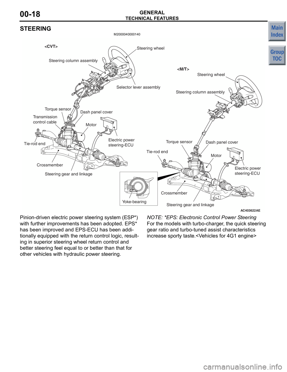
Pinion -driven electric p owe r ste ering system (ESP*)
with further improvement s has been adopted. EPS*
has been improved and EPS-ECU has been addi
-
tionally equipped with the return contro l logic, resu lt-
ing in superior stee ring whe el ret urn co ntrol and
better steering fee l equ al to or bett er than that for
other vehicles with hydraulic power steering.
NO TE: *EPS: Electronic Control Power S teerin g
For the mode ls with turb o-charge r, t he qu ick ste ering
gear rat io an d turbo -tuned a ssist chara cteristics
increase sporty tast e.
Page 221 of 364

GENERAL INFORMATION
FRONT AXLE26-2
GENERAL INFORMATION
M2260000100701
The front axle consists of front hub, wheel bearing,
knuckles and driveshafts, and has the following fea
-
tures:
•The wheel bearing incorporates magnetic
encoder for wheel speed sensing.
•The driveshaft incorporates EBJ-TJ type constant
velocity joint <4A9-CVT, 4A9-M/T (LS)>,
EBJ-ETJ type constant velocity joint <4A9-M/T
(VR)>, BJ-TJ type constant velocity joint <4G1>.
•The dynamic damper is mounted to reduce differ-
ential gear noise.
•The bracket assembly is mounted to reduce
torque steer. < 4G1>
•For environmental protection, a lead-free grease
is used on the joints.
EBJ(Eight Ball Fixed Joint):The use of the
smaller-sized eight balls inside the joint achieves
weight saving and compact size compared with a
BJ(Birfield Joint).
ETJ(Eco type Tripod Joint):This joint achieves
weight saving and compact size compared with a
TJ(Tripod Joint).
BJ:Birfield Joint
TJ:Tripod Joint
SPECIFICATIONS
Item4A94G1
CVTM/T
LSVR
Wheel bearingTy p eDouble-row angular contact ball bearing
Bearing (OD x ID) mm76 × 4076 × 4076 × 4076 × 40
DriveshaftJoint typeOuterEBJEBJEBJBJ
InnerTJTJETJTJ
Length (joint to joint)
× diameter mm
LH377 × 21.2377 × 21.2379 × 23352 × 24.9
RH688 × 21.2688 × 21.2664.3 × 23378.2 × 24.9
Page 236 of 364
GENERAL INFORMATION
POWER STEERING37-3
CONSTRUCTION DIAGRAM
AC405883AB
Steering wheel
Steering column assembly
Selector lever assembly
Electric power
steering-ECU
Motor
Torque sensor
Tie-rod end Steering gearDash panel cover
Page 237 of 364
AC405884AB
Steering wheel
Steering column assembly
Electric power
steering-ECU
Motor
Torque sensor
Tie-rod end
Yoke bearing
Steering gearDash panel cover
GENER
A L IN FORMA T ION
POWER ST E E RING37-4
Page 240 of 364

ELECTRICAL POWER STEERING
POWER STEERING37-7
ELECTRICAL POWER STEERING
GENERAL INFORMATIONM2370000100862
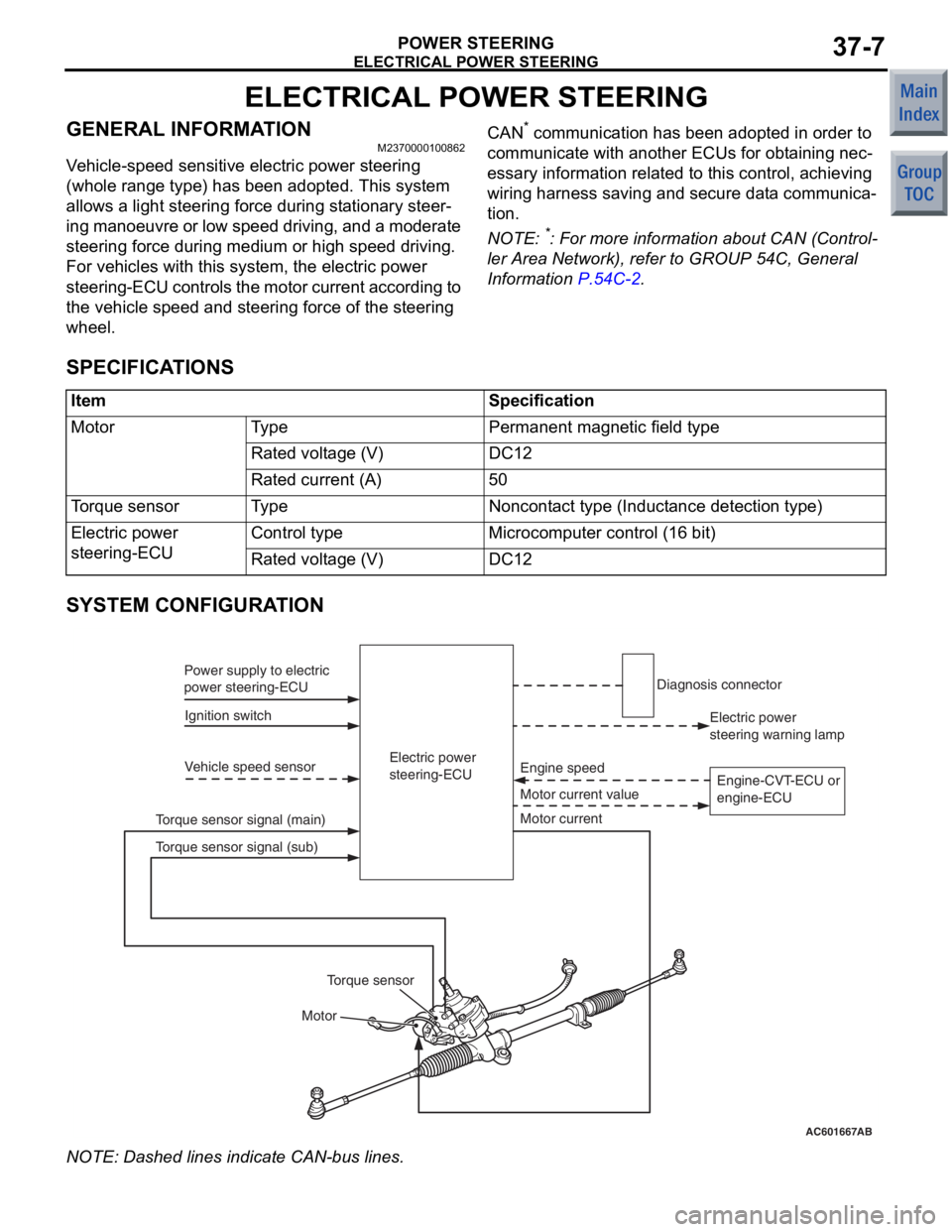
Vehicle-speed sensitive electric power steering
(whole range type) has been adopted. This system
allows a light steering force during stationary steer
-
ing manoeuvre or low speed driving, and a moderate
steering force during medium or high speed driving.
For vehicles with this system, the electric power
steering-ECU controls the motor current according to
the vehicle speed and steering force of the steering
wheel.
CAN* communication has been adopted in order to
communicate with another ECUs for obtaining nec
-
essary information related to this control, achieving
wiring harness saving and secure data communica
-
tion.
NOTE: *: For more information about CAN (Control-
ler Area Network), refer to GROUP 54C, General
Information
P.54C-2.
SPECIFICATIONS
ItemSpecification
MotorTy p ePermanent magnetic field type
Rated voltage (V)DC12
Rated current (A)50
Torque sensorTy p eNoncontact type (Inductance detection type)
Electric power
steering-ECUControl typeMicrocomputer control (16 bit)
Rated voltage (V)DC12
SYSTEM CONFIGURATION
AC601667AB
Electric power
steering-ECU
Ignition switch
Power supply to electric
power steering-ECU
Vehicle speed sensor
Motor Motor current value Engine speed
Torque sensor signal (main) Electric power
steering warning lamp
Diagnosis connector
Motor current
Torque sensor
Torque sensor signal (sub) Engine-CVT-ECU or
engine-ECU
NO
TE: Dash ed lines indicat e CAN-bu s lines.
Page 241 of 364

ELECTRICAL POWER STEERING
POWER STEERING37-8
ELECTRICAL PARTS AND FUNCTIONS
Parts nameDescription about function
SensorVehicle speed sensor (ABS-ECU)Sends the vehicle speed signal to the electric power
steering-ECU.
Torque sensorDetects a steering force, converts it into the voltage signal,
and then sends the signal to the electric power
steering-ECU.
ActuatorMotorGenerates assist torque by the steering operation to the
steering gear using the signals sent from the electric power
steering-ECU.
Electric power steering warning
lampWarns a driver of the system malfunction using the signal
sent from the electric power steering-ECU.
Electric power steering-ECUControl the actuator (motor) based on the signal sent from
sensor.
Controls the self-diagnostic fu nction and fail-safe function.
Controls diagnostic function (Compatible with M.U.T.-III).
GENERAL DESCRIPTION ON SYSTEM
AC207803
AC206444
AC206443
AB
Electric power
steering-ECU
Glove box
Torque sensor
Motor
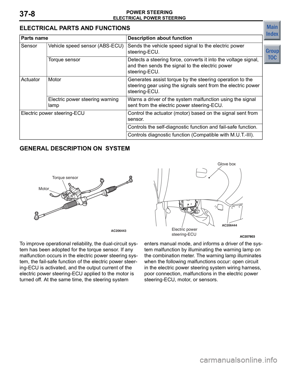
T o improve opera t iona l reliabi lity , th e dual-circuit sys-
tem ha s be en ad opted f o r the t o rque sensor . If a n y
malfunct
i on occurs in the electric power st eering sys
-
tem, the fail-sa f e fun c tio n of th e ele c tric power steer-
ing-ECU is activated, and the ou tput current of the
electric power steerin
g-ECU a pplied to the motor is
turned o
f f. At th e sa me time, the steerin g syste m enters man ual mode, and informs a dr iver of the sys
-
tem malfu
n ction by illuminating th e warnin g lamp on
the
comb in at io n me te r . Th e warn in g la mp il lu min a te s
wh
en the following malfu n ct ions occur: ope n circuit
in the
e l ectric power stee ring system wiring harness,
poor connectio
n , ma lfunction s in the e l ectric power
steering-ECU, mo
tor , or sensors.