2006 MERCEDES-BENZ SPRINTER ECO mode
[x] Cancel search: ECO modePage 1062 of 2305
The two washer nozzles have integral mounts with
snap features that secure them near the tops of the
two wiper arms on the windshield. The lower surface
of the washer nozzle has an integral barbed nipple
that connects to the washer hose, and three nozzle
orifices are oriented to dispense the washer fluid on
the windshield glass throughout the wiped area of
the glass (Fig. 15). The washer nozzles are con-
structed entirely of molded plastic. The washer noz-
zles cannot be adjusted or repaired and, if faulty or
damaged, they must be replaced.
OPERATION
The two washer nozzles are designed to dispense
washer fluid into the wiper pattern area on the out-
side of the windshield glass. Pressurized washer fluid
is fed to each nozzle from the washer reservoir by the
washer pump/motor through rubber hoses, which are
attached to a barbed nipple on the underside of each
washer nozzle below the wiper arm. The three ori-
fices of each nozzle causes the pressurized washer
fluid to be emitted generously in several streams
throughout the travel of the wiper arm to more effec-
tively cover a larger area of the glass to be cleaned.
REMOVAL
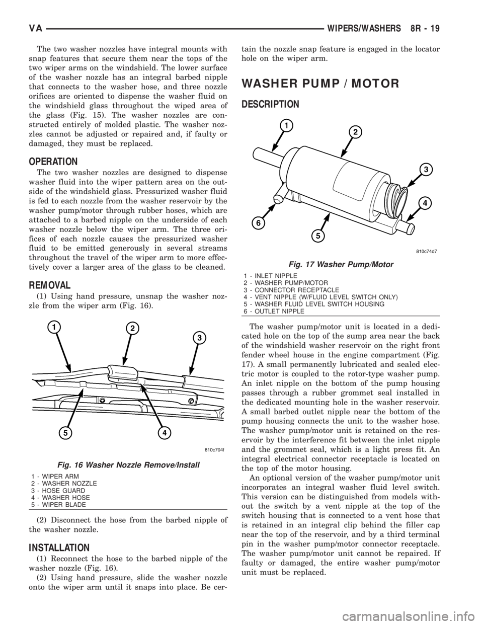
(1) Using hand pressure, unsnap the washer noz-
zle from the wiper arm (Fig. 16).
(2) Disconnect the hose from the barbed nipple of
the washer nozzle.
INSTALLATION
(1) Reconnect the hose to the barbed nipple of the
washer nozzle (Fig. 16).
(2) Using hand pressure, slide the washer nozzle
onto the wiper arm until it snaps into place. Be cer-tain the nozzle snap feature is engaged in the locator
hole on the wiper arm.
WASHER PUMP / MOTOR
DESCRIPTION
The washer pump/motor unit is located in a dedi-
cated hole on the top of the sump area near the back
of the windshield washer reservoir on the right front
fender wheel house in the engine compartment (Fig.
17). A small permanently lubricated and sealed elec-
tric motor is coupled to the rotor-type washer pump.
An inlet nipple on the bottom of the pump housing
passes through a rubber grommet seal installed in
the dedicated mounting hole in the washer reservoir.
A small barbed outlet nipple near the bottom of the
pump housing connects the unit to the washer hose.
The washer pump/motor unit is retained on the res-
ervoir by the interference fit between the inlet nipple
and the grommet seal, which is a light press fit. An
integral electrical connector receptacle is located on
the top of the motor housing.
An optional version of the washer pump/motor unit
incorporates an integral washer fluid level switch.
This version can be distinguished from models with-
out the switch by a vent nipple at the top of the
switch housing that is connected to a vent hose that
is retained in an integral clip behind the filler cap
near the top of the reservoir, and by a third terminal
pin in the washer pump/motor connector receptacle.
The washer pump/motor unit cannot be repaired. If
faulty or damaged, the entire washer pump/motor
unit must be replaced.
Fig. 16 Washer Nozzle Remove/Install
1 - WIPER ARM
2 - WASHER NOZZLE
3 - HOSE GUARD
4 - WASHER HOSE
5 - WIPER BLADE
Fig. 17 Washer Pump/Motor
1 - INLET NIPPLE
2 - WASHER PUMP/MOTOR
3 - CONNECTOR RECEPTACLE
4 - VENT NIPPLE (W/FLUID LEVEL SWITCH ONLY)
5 - WASHER FLUID LEVEL SWITCH HOUSING
6 - OUTLET NIPPLE
VAWIPERS/WASHERS 8R - 19
Page 1702 of 2305
FUEL QUANTITY CONTROL
VA LV E
DESCRIPTION
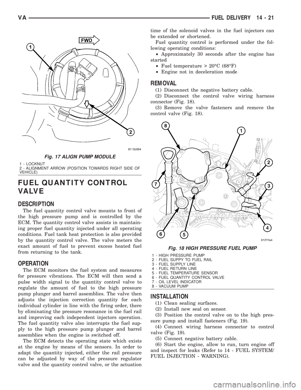
The fuel quantity control valve mounts to front of
the high pressure pump and is controlled by the
ECM. The quantity control valve assists in maintain-
ing proper fuel quantity injected under all operating
conditions. Fuel tank heat protection is also provided
by the quantity control valve. The valve meters the
exact amount of fuel to prevent excess heated fuel
from returning to the tank.
OPERATION
The ECM monitors the fuel system and measures
for pressure vibrations. The ECM will then send a
pulse width signal to the quantity control valve to
regulate the amount of fuel to the high pressure
pump plunger and barrel assemblies. The valve then
adjusts the injection correction quantity for each
individual cylinder in line with the firing order, there
by eliminating the pressure resonance in the fuel rail
and improving each independent injectors operation.
The fuel quantity valve also interrupts the fuel sup-
ply to the high pressure pump plunger and barrel
assemblies when the engine is switched off.
The ECM detects the operating state which exists
at the engine by means of the sensors. In order to
adapt the quantity injected, either the rail pressure
can be adjusted by way of the pressure regulator
valve and the quantity control valve, or the actuationtime of the solenoid valves in the fuel injectors can
be extended or shortened.
Fuel quantity control is performed under the fol-
lowing operating conditions:
²Approximately 30 seconds after the engine has
started
²Fuel temperature > 20ÉC (68ÉF)
²Engine not in deceleration mode
REMOVAL
(1) Disconnect the negative battery cable.
(2) Disconnect the control valve wiring harness
connector (Fig. 18).
(3) Remove the valve fasteners and remove the
control valve (Fig. 18).
INSTALLATION
(1) Clean sealing surfaces.
(2) Install new seal on sensor.
(3) Position the control valve on to the high pres-
sure pump and install fasteners (Fig. 19).
(4) Connect wiring harness connector to control
valve (Fig. 19).
(5) Connect negative battery cable.
(6) Start the engine, allow to run, turn engine off
and inspect for leaks (Refer to 14 - FUEL SYSTEM/
FUEL INJECTION - WARNING).
Fig. 17 ALIGN PUMP MODULE
1 - LOCKNUT
2 - ALIGNMENT ARROW (POSITION TOWARDS RIGHT SIDE OF
VEHICLE)
Fig. 18 HIGH PRESSURE FUEL PUMP
1 - HIGH PRESSURE PUMP
2 - FUEL SUPPY TO FUEL RAIL
3 - FUEL SUPPLY LINE
4 - FUEL RETURN LINE
5 - FUEL TEMPERATURE SENSOR
6 - FUEL QUANTITY CONTROL VALVE
7 - OIL LEVEL INDICATOR
8 - VACUUM PUMP
VAFUEL DELIVERY 14 - 21
Page 1714 of 2305
(2) Position the sensor (Fig. 3) and install the fas-
teners.
(3) Connect the negative battery cable.
BOOST PRESSURE SENSOR
DESCRIPTION
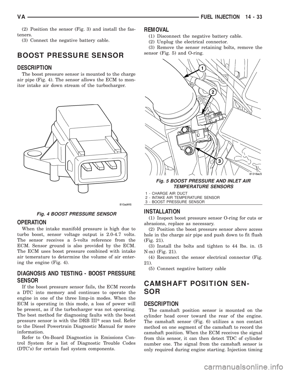
The boost pressure sensor is mounted to the charge
air pipe (Fig. 4). The sensor allows the ECM to mon-
itor intake air down stream of the turbocharger.
OPERATION
When the intake manifold pressure is high due to
turbo boost, sensor voltage output is 2.0-4.7 volts.
The sensor receives a 5-volts reference from the
ECM. Sensor ground is also provided by the ECM.
The ECM uses boost pressure combined with intake
air temerature to determine the volume of air enter-
ing the engine (Fig. 4).
DIAGNOSIS AND TESTING - BOOST PRESSURE
SENSOR
If the boost pressure sensor fails, the ECM records
a DTC into memory and continues to operate the
engine in one of the three limp-in modes. When the
ECM is operating in this mode, a loss of power will
be present, as if the turbocharger was not operating.
The best method for diagnosing faults with the boost
pressure sensor is with the DRB IIItscan tool. Refer
to the Diesel Powertrain Diagnostic Manual for more
information.
Refer to On-Board Diagnostics in Emissions Con-
trol System for a list of Diagnostic Trouble Codes
(DTC's) for certain fuel system components.
REMOVAL
(1) Disconnect the negative battery cable.
(2) Unplug the electrical connector.
(3) Remove the sensor retaining bolts, remove the
sensor (Fig. 5) and O-ring.
INSTALLATION
(1) Inspect boost pressure sensor O-ring for cuts or
abrasions, replace as necessary.
(2) Position the boost pressure sensor above access
hole in the charge air pipe and push down to fit flush
(Fig. 21).
(3) Install the bolts and tighten to 44 lbs. in. (5
N´m) (Fig. 21).
(4) Reconnect the sensor electrical connector (Fig.
21).
(5) Connect negative battery cable
CAMSHAFT POSITION SEN-
SOR
DESCRIPTION
The camshaft position sensor is mounted on the
cylinder head cover toward the rear of the engine.
The camshaft sensor (Fig. 6) utilizes a non contact
method on one segment of the camshaft to record the
camshaft position. When the ECM receives the signal
from this sensor, it can then detect TDC of cylinder
number one. The signal from the camshaft sensor is
only required during engine starting. Injection timing
Fig. 4 BOOST PRESSURE SENSOR
Fig. 5 BOOST PRESSURE AND INLET AIR
TEMPERATURE SENSORS
1 - CHARGE AIR DUCT
2 - INTAKE AIR TEMPERATURE SENSOR
3 - BOOST PRESSURE SENSOR
VAFUEL INJECTION 14 - 33
Page 1748 of 2305
flexible adaptation to different vehicle and engine
variants.
EMERGENCY RUNNING FUNCTION
In order to ensure a safe driving state and to pre-
vent damage to the automatic transmission, the TCM
control module switches to limp-home mode in the
event of critical faults. A diagnostic trouble code
(DTC) assigned to the fault is stored in memory. All
solenoid and regulating valves are thus de-energized.
The net effect is:
²The last engaged gear remains engaged.
²The modulating pressure and shift pressures
rise to the maximum levels.
²The torque converter lockup clutch is deacti-
vated.
In order to preserve the operability of the vehicle
to some extent, the hydraulic control can be used to
engage 2nd gear or reverse using the following pro-
cedure:²Stop the vehicle.
²Move selector lever to ªPº.
²Switch off engine.
²Wait at least 10 seconds.
²Start engine.
²Move selector lever to D: 2nd gear.
²Move selector lever to R: Reverse gear.
The limp-home function remains active until the
DTC is rectified or the stored DTC is erased with the
appropriate scan tool. Sporadic faults can be reset
via ignition OFF/ON.
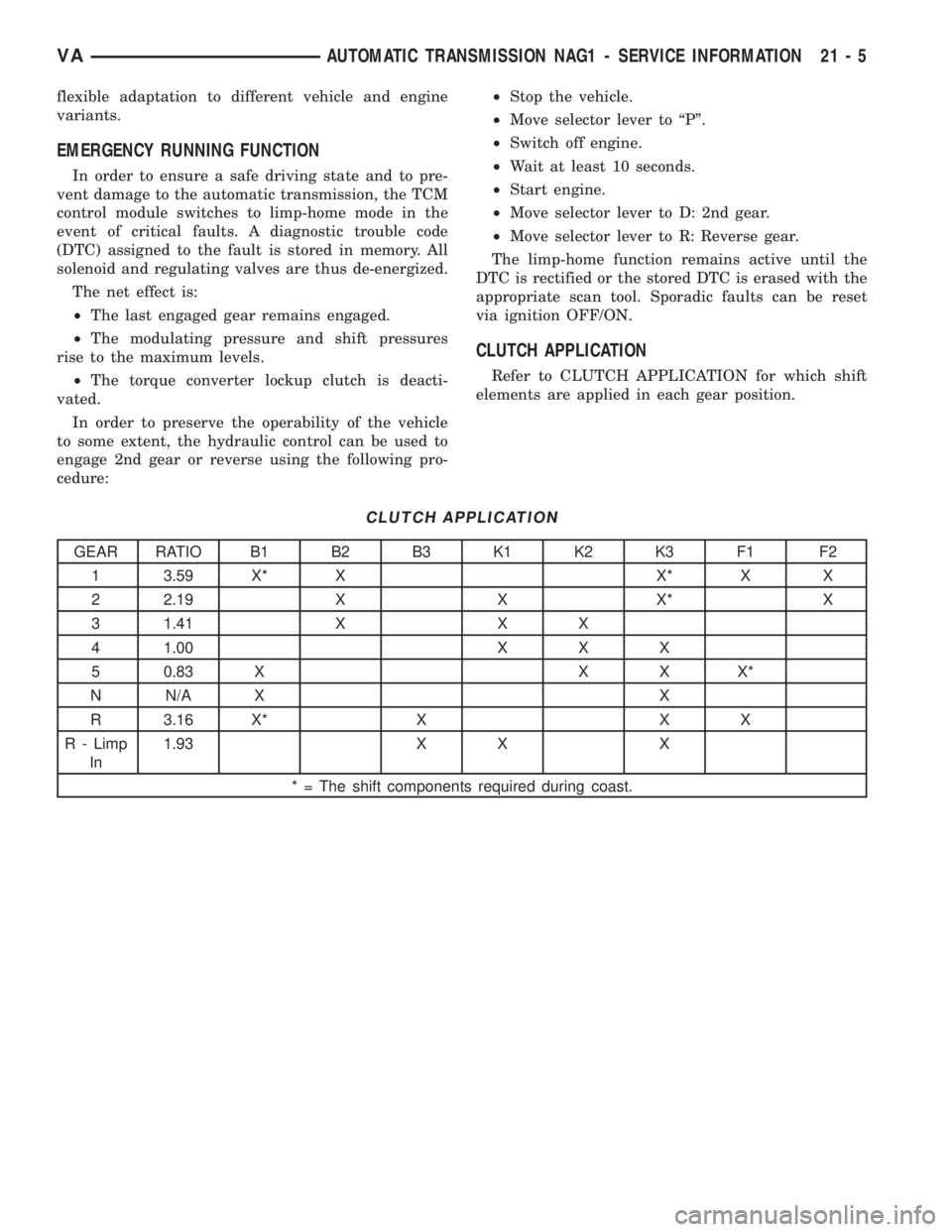
CLUTCH APPLICATION
Refer to CLUTCH APPLICATION for which shift
elements are applied in each gear position.
CLUTCH APPLICATION
GEAR RATIO B1 B2 B3 K1 K2 K3 F1 F2
1 3.59 X* X X* X X
2 2.19 X X X* X
3 1.41 X X X
4 1.00 X X X
5 0.83 X X X X*
N N/A X X
R 3.16 X* X X X
R - Limp
In1.93 X X X
* = The shift components required during coast.
VAAUTOMATIC TRANSMISSION NAG1 - SERVICE INFORMATION 21 - 5
Page 1875 of 2305
CAUSES OF BURNT FLUID
Burnt, discolored fluid is a result of overheating
which has three primary causes.
1. Internal clutch slippage, usually caused by low
line pressure, inadequate clutch apply pressure, or
clutch seal failure.
2. A result of restricted fluid flow through the
main and/or auxiliary cooler. This condition is usu-
ally the result of a faulty or improperly installed
drainback valve, a damaged oil cooler, or severe
restrictions in the coolers and lines caused by debris
or kinked lines.
3. Heavy duty operation with a vehicle not prop-
erly equipped for this type of operation. Trailer tow-
ing or similar high load operation will overheat the
transmission fluid if the vehicle is improperly
equipped. Such vehicles should have an auxiliary
transmission fluid cooler, a heavy duty cooling sys-
tem, and the engine/axle ratio combination needed to
handle heavy loads.
FLUID CONTAMINATION
Transmission fluid contamination is generally a
result of:
²adding incorrect fluid
²failure to clean dipstick and fill tube when
checking level
²engine coolant entering the fluid
²internal failure that generates debris
²overheat that generates sludge (fluid break-
down)
²failure to replace contaminated converter after
repair
The use of non-recommended fluids can result in
transmission failure. The usual results are erratic
shifts, slippage, abnormal wear and eventual failure
due to fluid breakdown and sludge formation. Avoid
this condition by using recommended fluids only.
The dipstick cap and fill tube should be wiped
clean before checking fluid level. Dirt, grease and
other foreign material on the cap and tube could fall
into the tube if not removed beforehand. Take the
time to wipe the cap and tube clean before withdraw-
ing the dipstick.
Engine coolant in the transmission fluid is gener-
ally caused by a cooler malfunction. The only remedy
is to replace the radiator as the cooler in the radiator
is not a serviceable part. If coolant has circulated
through the transmission, an overhaul is necessary.
The torque converter should be replaced whenever
a failure generates sludge and debris. This is neces-
sary because normal converter flushing procedures
will not remove all contaminants.
STANDARD PROCEDURE
CHECK OIL LEVEL
(1) Verify that the vehicle is parked on a level sur-
face.
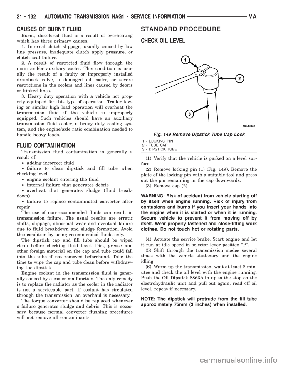
(2) Remove locking pin (1) (Fig. 149). Remove the
plate of the locking pin with a suitable tool and press
out the pin remaining in the cap downwards.
(3) Remove cap (2).
WARNING: Risk of accident from vehicle starting off
by itself when engine running. Risk of injury from
contusions and burns if you insert your hands into
the engine when it is started or when it is running.
Secure vehicle to prevent it from moving off by
itself. Wear properly fastened and close-fitting work
clothes. Do not touch hot or rotating parts.
(4) Actuate the service brake. Start engine and let
it run at idle speed in selector lever position ªPº.
(5) Shift through the transmission modes several
times with the vehicle stationary and the engine
idling
(6) Warm up the transmission, wait at least 2 min-
utes and check the oil level with the engine running.
Push the Oil Dipstick 8863A in up to the stop on the
electrohydraulic unit and pull out again, read off oil
level, repeat if necessary.
NOTE: The dipstick will protrude from the fill tube
approximately 75mm (3 inches) when installed.
Fig. 149 Remove Dipstick Tube Cap Lock
1 - LOCKING PIN
2 - TUBE CAP
3 - DIPSTICK TUBE
21 - 132 AUTOMATIC TRANSMISSION NAG1 - SERVICE INFORMATIONVA
Page 1940 of 2305
WHEELS
DESCRIPTION
Original equipment wheels are designed for the
specified Maximum Vehicle Capacity.
All models use steel or aluminum wheels.
Aluminum wheels require special balance weights
and alignment equipment.
(1) On vehicles equipped with dual rear wheels,
The slots in the wheel must be aligned to provide
access to the valve stem.
OPERATION
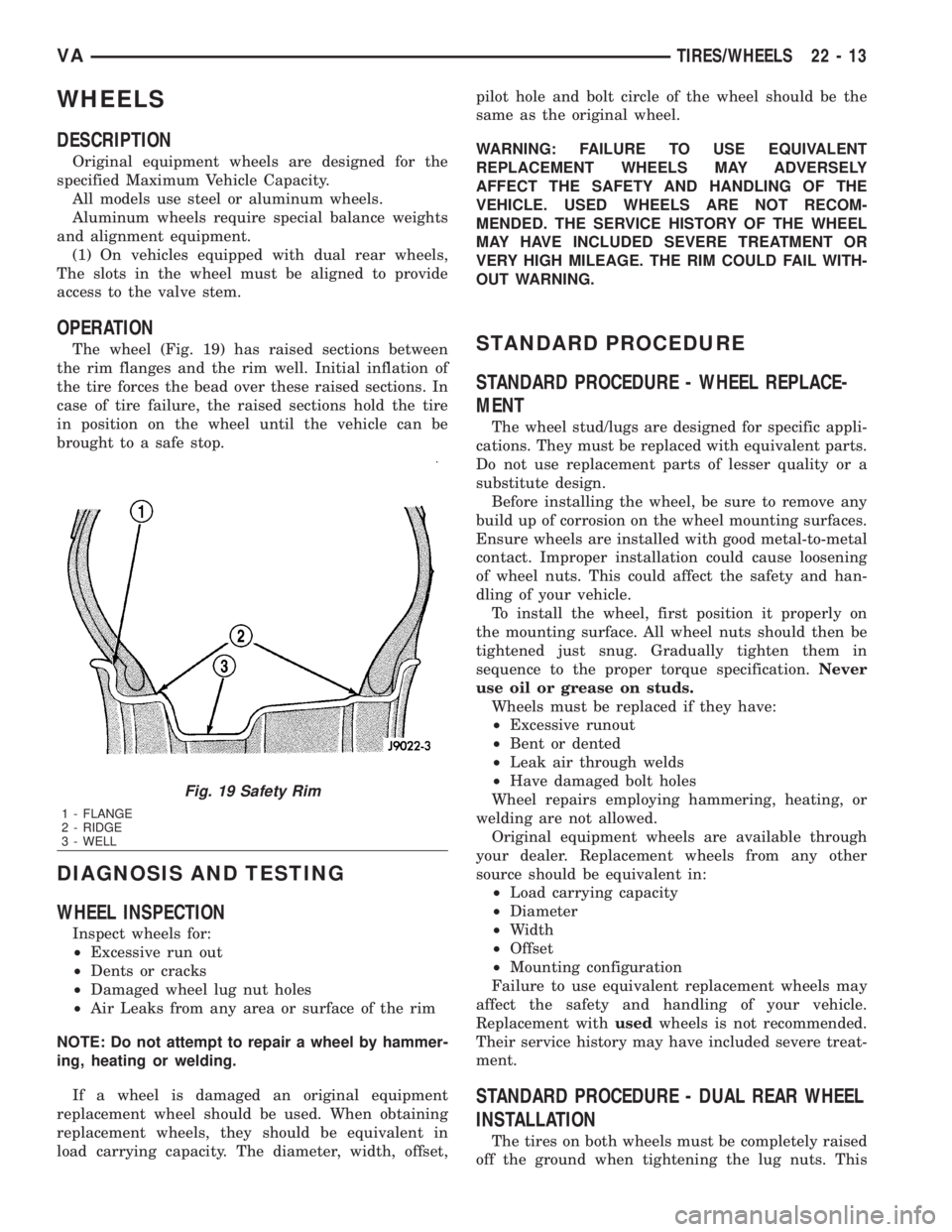
The wheel (Fig. 19) has raised sections between
the rim flanges and the rim well. Initial inflation of
the tire forces the bead over these raised sections. In
case of tire failure, the raised sections hold the tire
in position on the wheel until the vehicle can be
brought to a safe stop.
DIAGNOSIS AND TESTING
WHEEL INSPECTION
Inspect wheels for:
²Excessive run out
²Dents or cracks
²Damaged wheel lug nut holes
²Air Leaks from any area or surface of the rim
NOTE: Do not attempt to repair a wheel by hammer-
ing, heating or welding.
If a wheel is damaged an original equipment
replacement wheel should be used. When obtaining
replacement wheels, they should be equivalent in
load carrying capacity. The diameter, width, offset,pilot hole and bolt circle of the wheel should be the
same as the original wheel.
WARNING: FAILURE TO USE EQUIVALENT
REPLACEMENT WHEELS MAY ADVERSELY
AFFECT THE SAFETY AND HANDLING OF THE
VEHICLE. USED WHEELS ARE NOT RECOM-
MENDED. THE SERVICE HISTORY OF THE WHEEL
MAY HAVE INCLUDED SEVERE TREATMENT OR
VERY HIGH MILEAGE. THE RIM COULD FAIL WITH-
OUT WARNING.
STANDARD PROCEDURE
STANDARD PROCEDURE - WHEEL REPLACE-
MENT
The wheel stud/lugs are designed for specific appli-
cations. They must be replaced with equivalent parts.
Do not use replacement parts of lesser quality or a
substitute design.
Before installing the wheel, be sure to remove any
build up of corrosion on the wheel mounting surfaces.
Ensure wheels are installed with good metal-to-metal
contact. Improper installation could cause loosening
of wheel nuts. This could affect the safety and han-
dling of your vehicle.
To install the wheel, first position it properly on
the mounting surface. All wheel nuts should then be
tightened just snug. Gradually tighten them in
sequence to the proper torque specification.Never
use oil or grease on studs.
Wheels must be replaced if they have:
²Excessive runout
²Bent or dented
²Leak air through welds
²Have damaged bolt holes
Wheel repairs employing hammering, heating, or
welding are not allowed.
Original equipment wheels are available through
your dealer. Replacement wheels from any other
source should be equivalent in:
²Load carrying capacity
²Diameter
²Width
²Offset
²Mounting configuration
Failure to use equivalent replacement wheels may
affect the safety and handling of your vehicle.
Replacement withusedwheels is not recommended.
Their service history may have included severe treat-
ment.
STANDARD PROCEDURE - DUAL REAR WHEEL
INSTALLATION
The tires on both wheels must be completely raised
off the ground when tightening the lug nuts. This
Fig. 19 Safety Rim
1 - FLANGE
2 - RIDGE
3 - WELL
VATIRES/WHEELS 22 - 13
Page 2038 of 2305
HEATING & AIR CONDITIONING
TABLE OF CONTENTS
page page
HEATING & AIR CONDITIONING
DESCRIPTION..........................1
OPERATION............................2
DIAGNOSIS AND TESTING
A/C PERFORMANCE....................3
HEATER PERFORMANCE TEST...........5
ATC FUNCTION TEST...................6
SPECIFICATIONS
HEATING-A/C SYSTEM..................6CONTROLS-FRONT........................8
CONTROLS - REAR......................24
DISTRIBUTION - FRONT...................45
DISTRIBUTION - REAR....................52
PLUMBING.............................60
CABIN HEATER.........................104
HEATING & AIR CONDITION-
ING
DESCRIPTION
An automatic temperature control (ATC) single
zone type heating-A/C system is standard equipment
on this model.
To maintain the performance level of the heating,
ventilation and air conditioning (HVAC) system, the
engine cooling system must be properly maintained.
The use of a bug screen is not recommended. Any
obstructions in front of the radiator or A/C condenser
will reduce the performance of the A/C and engine
cooling systems.
The engine cooling system includes the radiator,
thermostat, radiator hoses and the engine coolant
pump. Refer to 7 - Cooling for more information
before opening or attempting any service to the
engine cooling system.
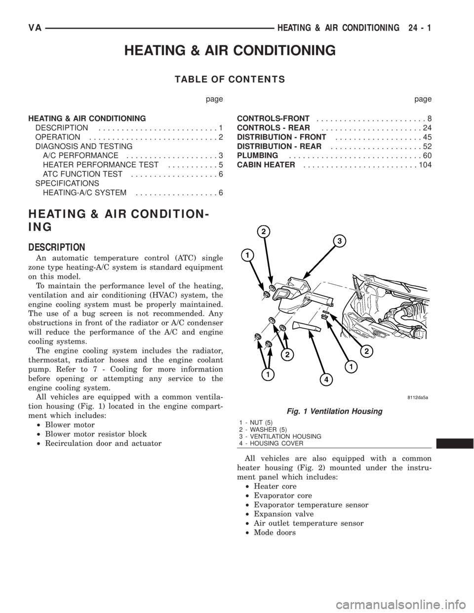
All vehicles are equipped with a common ventila-
tion housing (Fig. 1) located in the engine compart-
ment which includes:
²Blower motor
²Blower motor resistor block
²Recirculation door and actuator
All vehicles are also equipped with a common
heater housing (Fig. 2) mounted under the instru-
ment panel which includes:
²Heater core
²Evaporator core
²Evaporator temperature sensor
²Expansion valve
²Air outlet temperature sensor
²Mode doors
Fig. 1 Ventilation Housing
1 - NUT (5)
2 - WASHER (5)
3 - VENTILATION HOUSING
4 - HOUSING COVER
VAHEATING & AIR CONDITIONING 24 - 1
Page 2039 of 2305
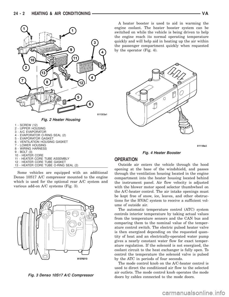
Some vehicles are equipped with an additional
Denso 10S17 A/C compressor mounted to the engine
which is used for the optional rear A/C system and
various add-on A/C systems (Fig. 3).A heater booster is used to aid in warming the
engine coolant. The heater booster system can be
switched on while the vehicle is being driven to help
the engine reach its normal operating temperature
quickly and will help aid in heating up the air within
the passenger compartment quickly when requested
by the operator (Fig. 4).
OPERATION
Outside air enters the vehicle through the hood
opening at the base of the windshield, and passes
through the ventilation housing located in the engine
compartment into the heater housing located behind
the instrument panel. Air flow velocity is adjusted
with the blower motor speed selector thumbwheel on
the A/C-heater control. The air intake openings must
be kept free of snow, ice, leaves, and other obstruc-
tions for the HVAC system to receive a sufficient vol-
ume of outside air.
The automatic temperature control (ATC) system
controls interior temperature by taking actual values
from the temperature sensors and the CAN bus and
comparing them to the nominal value of the temper-
ature control switch. The electric pulsed heater valve
is then energized depending on the requested quan-
tity of heat and an electrically-operated water pump
gives a nearly constant water flow for exact temper-
ature regulation. If the solenoid is not energized, the
coolant circuit to the heat exchanger is fully open. To
control the temperature the solenoid valve is pulsed
by the ATC in periods of four seconds.
The mode control knob on the A/C-heater control is
used to direct the conditioned air flow to the selected
air outlets. The mode control knob operates the mode
doors by cables connected to the mode doors.
Fig. 2 Heater Housing
1 - SCREW (12)
2 - UPPER HOUSING
3 - A/C EVAPORATOR
4 - EVAPORATOR O-RING SEAL (2)
5 - EVAPORATOR GASKET
6 - VENTILATION HOUSING GASKET
7 - LOWER HOUSING
8 - WIRING HARNESS
9 - BOLT (3)
10 - HEATER CORE
11 - HEATER CORE TUBE ASSEMBLY
12 - HEATER CORE TUBE GASKET
13 - HEATER CORE TUBE O-RING SEAL (2)
Fig. 3 Denso 10S17 A/C Compressor
Fig. 4 Heater Booster
24 - 2 HEATING & AIR CONDITIONINGVA