2006 MERCEDES-BENZ SPRINTER window
[x] Cancel search: windowPage 1514 of 2305
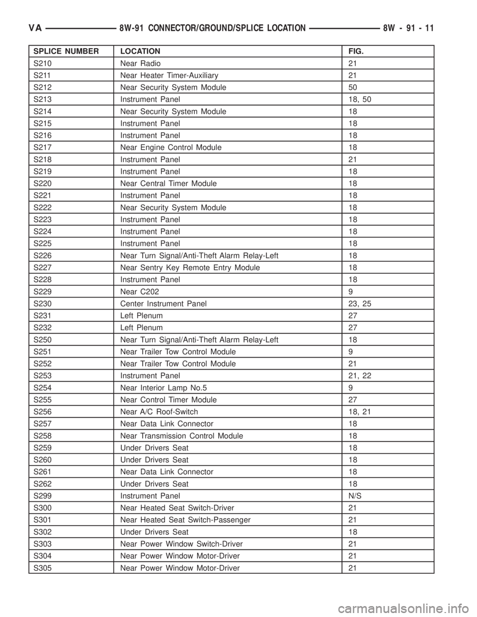
SPLICE NUMBER LOCATION FIG.
S210 Near Radio 21
S211 Near Heater Timer-Auxiliary 21
S212 Near Security System Module 50
S213 Instrument Panel 18, 50
S214 Near Security System Module 18
S215 Instrument Panel 18
S216 Instrument Panel 18
S217 Near Engine Control Module 18
S218 Instrument Panel 21
S219 Instrument Panel 18
S220 Near Central Timer Module 18
S221 Instrument Panel 18
S222 Near Security System Module 18
S223 Instrument Panel 18
S224 Instrument Panel 18
S225 Instrument Panel 18
S226 Near Turn Signal/Anti-Theft Alarm Relay-Left 18
S227 Near Sentry Key Remote Entry Module 18
S228 Instrument Panel 18
S229 Near C202 9
S230 Center Instrument Panel 23, 25
S231 Left Plenum 27
S232 Left Plenum 27
S250 Near Turn Signal/Anti-Theft Alarm Relay-Left 18
S251 Near Trailer Tow Control Module 9
S252 Near Trailer Tow Control Module 21
S253 Instrument Panel 21, 22
S254 Near Interior Lamp No.5 9
S255 Near Control Timer Module 27
S256 Near A/C Roof-Switch 18, 21
S257 Near Data Link Connector 18
S258 Near Transmission Control Module 18
S259 Under Drivers Seat 18
S260 Under Drivers Seat 18
S261 Near Data Link Connector 18
S262 Under Drivers Seat 18
S299 Instrument Panel N/S
S300 Near Heated Seat Switch-Driver 21
S301 Near Heated Seat Switch-Passenger 21
S302 Under Drivers Seat 18
S303 Near Power Window Switch-Driver 21
S304 Near Power Window Motor-Driver 21
S305 Near Power Window Motor-Driver 21
VA8W-91 CONNECTOR/GROUND/SPLICE LOCATION 8W - 91 - 11
Page 1515 of 2305
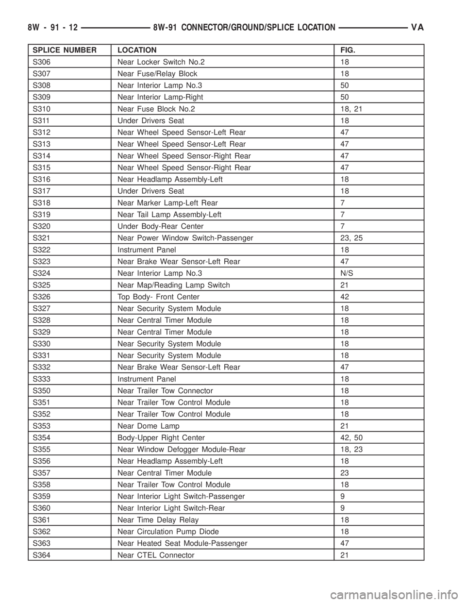
SPLICE NUMBER LOCATION FIG.
S306 Near Locker Switch No.2 18
S307 Near Fuse/Relay Block 18
S308 Near Interior Lamp No.3 50
S309 Near Interior Lamp-Right 50
S310 Near Fuse Block No.2 18, 21
S311 Under Drivers Seat 18
S312 Near Wheel Speed Sensor-Left Rear 47
S313 Near Wheel Speed Sensor-Left Rear 47
S314 Near Wheel Speed Sensor-Right Rear 47
S315 Near Wheel Speed Sensor-Right Rear 47
S316 Near Headlamp Assembly-Left 18
S317 Under Drivers Seat 18
S318 Near Marker Lamp-Left Rear 7
S319 Near Tail Lamp Assembly-Left 7
S320 Under Body-Rear Center 7
S321 Near Power Window Switch-Passenger 23, 25
S322 Instrument Panel 18
S323 Near Brake Wear Sensor-Left Rear 47
S324 Near Interior Lamp No.3 N/S
S325 Near Map/Reading Lamp Switch 21
S326 Top Body- Front Center 42
S327 Near Security System Module 18
S328 Near Central Timer Module 18
S329 Near Central Timer Module 18
S330 Near Security System Module 18
S331 Near Security System Module 18
S332 Near Brake Wear Sensor-Left Rear 47
S333 Instrument Panel 18
S350 Near Trailer Tow Connector 18
S351 Near Trailer Tow Control Module 18
S352 Near Trailer Tow Control Module 18
S353 Near Dome Lamp 21
S354 Body-Upper Right Center 42, 50
S355 Near Window Defogger Module-Rear 18, 23
S356 Near Headlamp Assembly-Left 18
S357 Near Central Timer Module 23
S358 Near Trailer Tow Control Module 18
S359 Near Interior Light Switch-Passenger 9
S360 Near Interior Light Switch-Rear 9
S361 Near Time Delay Relay 18
S362 Near Circulation Pump Diode 18
S363 Near Heated Seat Module-Passenger 47
S364 Near CTEL Connector 21
8W - 91 - 12 8W-91 CONNECTOR/GROUND/SPLICE LOCATIONVA
Page 1560 of 2305

Fig. 44 WINDOW MOTORS AND SPEAKERS
VA8W-91 CONNECTOR/GROUND/SPLICE LOCATION 8W - 91 - 57
Page 1571 of 2305
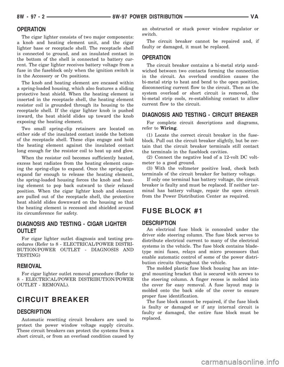
OPERATION
The cigar lighter consists of two major components:
a knob and heating element unit, and the cigar
lighter base or receptacle shell. The receptacle shell
is connected to ground, and an insulated contact in
the bottom of the shell is connected to battery cur-
rent. The cigar lighter receives battery voltage from a
fuse in the fuseblock only when the ignition switch is
in the Accessory or On positions.
The knob and heating element are encased within
a spring-loaded housing, which also features a sliding
protective heat shield. When the heating element is
inserted in the receptacle shell, the heating element
resistor coil is grounded through its housing to the
receptacle shell. If the cigar lighter knob is pushed
inward, the heat shield slides up toward the knob
exposing the heating element.
Two small spring-clip retainers are located on
either side of the insulated contact inside the bottom
of the receptacle shell. These clips engage and hold
the heating element against the insulated contact
long enough for the resistor coil to heat up and glow.
When the resistor coil becomes sufficiently heated,
excess heat radiates from the heating element caus-
ing the spring-clips to expand. Once the spring-clips
expand far enough to release the heating element,
the spring-loaded housing forces the knob and heat-
ing element to pop back outward to their relaxed
position. When the cigar lighter knob and element
are pulled out of the receptacle shell, the protective
heat shield slides downward on the housing so that
the heating element is recessed and shielded around
its circumference for safety.
DIAGNOSIS AND TESTING - CIGAR LIGHTER
OUTLET
For cigar lighter outlet diagnosis and testing pro-
cedures (Refer to 8 - ELECTRICAL/POWER DISTRI-
BUTION/POWER OUTLET - DIAGNOSIS AND
TESTING)
REMOVAL
For cigar lighter outlet removal procedure (Refer to
8 - ELECTRICAL/POWER DISTRIBUTION/POWER
OUTLET - REMOVAL).
CIRCUIT BREAKER
DESCRIPTION
Automatic resetting circuit breakers are used to
protect the power window voltage supply circuits.
These circuit breakers can protect the systems from a
short circuit, or from an overload condition caused byan obstructed or stuck power window regulator or
switch.
The circuit breaker cannot be repaired and, if
faulty or damaged, it must be replaced.
OPERATION
The circuit breaker contains a bi-metal strip sand-
wiched between two contacts forming the connection
in the circuit. An overload condition causes the
bi-metal strip to heat and bend to the open position,
disconnecting current flow to the circuit. Then as the
system overload or short circuit is removed, the
bi-metal strip cools, re-establishing contact to allow
current flow to the circuit.
DIAGNOSIS AND TESTING - CIRCUIT BREAKER
For complete circuit descriptions and diagrams,
refer toWiring.
(1) Locate the correct circuit breaker in the fuse-
block. Pull out the circuit breaker slightly, but be cer-
tain that the circuit breaker terminals still contact
the terminals in the fuseblock cavities.
(2) Connect the negative lead of a 12-volt DC volt-
meter to a good ground.
(3) With the voltmeter positive lead, check both
terminals of the circuit breaker for battery voltage.
If only one terminal has battery voltage, the circuit
breaker is faulty and must be replaced. If neither ter-
minal has battery voltage, repair the open circuit
from the Power Distribution Center as required.
FUSE BLOCK #1
DESCRIPTION
An electrical fuse block is concealed under the
driver side steering column. The fuse block serves to
distribute electrical current to many of the electrical
systems in the vehicle. The fuse block contains blade-
type mini fuses, relays and micro processors that
enable automatic control of some of the power distri-
bution circuits throughout the vehicle.
The molded plastic fuse block housing has an inte-
gral mounting bracket that is secured with screws to
the steering column. A finger recess is molded into
the cover for easy removal. A fuse layout map is
molded onto the back side of the cover to ensure
proper fuse identification.
The fuse block cannot be repaired, if the fuse block
is faulty or damaged or if any internal circuit is
faulty or damaged, the entire fuse block must be
replaced.
8W - 97 - 2 8W-97 POWER DISTRIBUTIONVA
Page 1945 of 2305
aligned and sealed. If component alignment or seal-
ing is necessary, refer to the appropriate section of
this group for proper procedures.
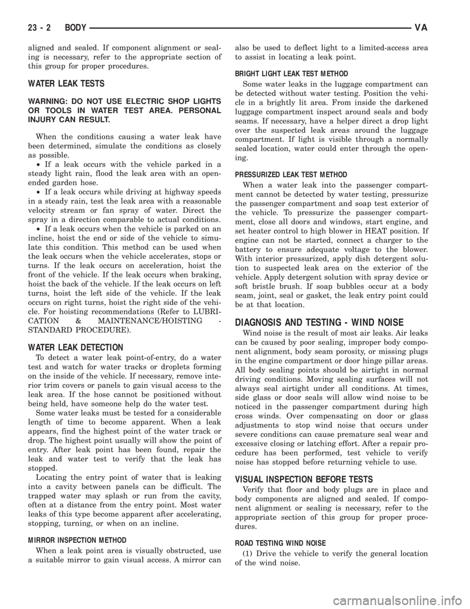
WATER LEAK TESTS
WARNING: DO NOT USE ELECTRIC SHOP LIGHTS
OR TOOLS IN WATER TEST AREA. PERSONAL
INJURY CAN RESULT.
When the conditions causing a water leak have
been determined, simulate the conditions as closely
as possible.
²If a leak occurs with the vehicle parked in a
steady light rain, flood the leak area with an open-
ended garden hose.
²If a leak occurs while driving at highway speeds
in a steady rain, test the leak area with a reasonable
velocity stream or fan spray of water. Direct the
spray in a direction comparable to actual conditions.
²If a leak occurs when the vehicle is parked on an
incline, hoist the end or side of the vehicle to simu-
late this condition. This method can be used when
the leak occurs when the vehicle accelerates, stops or
turns. If the leak occurs on acceleration, hoist the
front of the vehicle. If the leak occurs when braking,
hoist the back of the vehicle. If the leak occurs on left
turns, hoist the left side of the vehicle. If the leak
occurs on right turns, hoist the right side of the vehi-
cle. For hoisting recommendations (Refer to LUBRI-
CATION & MAINTENANCE/HOISTING -
STANDARD PROCEDURE).
WATER LEAK DETECTION
To detect a water leak point-of-entry, do a water
test and watch for water tracks or droplets forming
on the inside of the vehicle. If necessary, remove inte-
rior trim covers or panels to gain visual access to the
leak area. If the hose cannot be positioned without
being held, have someone help do the water test.
Some water leaks must be tested for a considerable
length of time to become apparent. When a leak
appears, find the highest point of the water track or
drop. The highest point usually will show the point of
entry. After leak point has been found, repair the
leak and water test to verify that the leak has
stopped.
Locating the entry point of water that is leaking
into a cavity between panels can be difficult. The
trapped water may splash or run from the cavity,
often at a distance from the entry point. Most water
leaks of this type become apparent after accelerating,
stopping, turning, or when on an incline.
MIRROR INSPECTION METHOD
When a leak point area is visually obstructed, use
a suitable mirror to gain visual access. A mirror canalso be used to deflect light to a limited-access area
to assist in locating a leak point.
BRIGHT LIGHT LEAK TEST METHOD
Some water leaks in the luggage compartment can
be detected without water testing. Position the vehi-
cle in a brightly lit area. From inside the darkened
luggage compartment inspect around seals and body
seams. If necessary, have a helper direct a drop light
over the suspected leak areas around the luggage
compartment. If light is visible through a normally
sealed location, water could enter through the open-
ing.
PRESSURIZED LEAK TEST METHOD
When a water leak into the passenger compart-
ment cannot be detected by water testing, pressurize
the passenger compartment and soap test exterior of
the vehicle. To pressurize the passenger compart-
ment, close all doors and windows, start engine, and
set heater control to high blower in HEAT position. If
engine can not be started, connect a charger to the
battery to ensure adequate voltage to the blower.
With interior pressurized, apply dish detergent solu-
tion to suspected leak area on the exterior of the
vehicle. Apply detergent solution with spray device or
soft bristle brush. If soap bubbles occur at a body
seam, joint, seal or gasket, the leak entry point could
be at that location.
DIAGNOSIS AND TESTING - WIND NOISE
Wind noise is the result of most air leaks. Air leaks
can be caused by poor sealing, improper body compo-
nent alignment, body seam porosity, or missing plugs
in the engine compartment or door hinge pillar areas.
All body sealing points should be airtight in normal
driving conditions. Moving sealing surfaces will not
always seal airtight under all conditions. At times,
side glass or door seals will allow wind noise to be
noticed in the passenger compartment during high
cross winds. Over compensating on door or glass
adjustments to stop wind noise that occurs under
severe conditions can cause premature seal wear and
excessive closing or latching effort. After a repair pro-
cedure has been performed, test vehicle to verify
noise has stopped before returning vehicle to use.
VISUAL INSPECTION BEFORE TESTS
Verify that floor and body plugs are in place and
body components are aligned and sealed. If compo-
nent alignment or sealing is necessary, refer to the
appropriate section of this group for proper proce-
dures.
ROAD TESTING WIND NOISE
(1) Drive the vehicle to verify the general location
of the wind noise.
23 - 2 BODYVA
Page 1948 of 2305
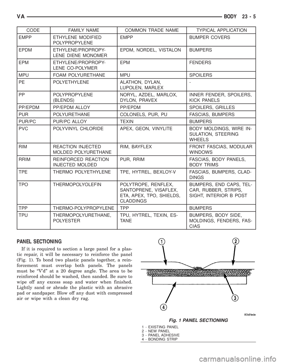
CODE FAMILY NAME COMMON TRADE NAME TYPICAL APPLICATION
EMPP ETHYLENE MODIFIED
POLYPROPYLENEEMPP BUMPER COVERS
EPDM ETHYLENE/PROPROPY-
LENE DIENE MONOMEREPDM, NORDEL, VISTALON BUMPERS
EPM ETHYLENE/PROPROPY-
LENE CO-POLYMEREPM FENDERS
MPU FOAM POLYURETHANE MPU SPOILERS
PE POLYETHYLENE ALATHON, DYLAN,
LUPOLEN, MARLEX-
PP POLYPROPYLENE
(BLENDS)NORYL, AZDEL, MARLOX,
DYLON, PRAVEXINNER FENDER, SPOILERS,
KICK PANELS
PP/EPDM PP/EPDM ALLOY PP/EPDM SPOILERS, GRILLES
PUR POLYURETHANE COLONELS, PUR, PU FASCIAS, BUMPERS
PUR/PC PUR/PC ALLOY TEXIN BUMPERS
PVC POLYVINYL CHLORIDE APEX, GEON, VINYLITE BODY MOLDINGS, WIRE IN-
SULATION, STEERING
WHEELS
RIM REACTION INJECTED
MOLDED POLYURETHANERIM, BAYFLEX FRONT FASCIAS, MODULAR
WINDOWS
RRIM REINFORCED REACTION
INJECTED MOLDEDPUR, RRIM FASCIAS, BODY PANELS,
BODY TRIMS
TPE THERMO POLYETHYLENE TPE, HYTREL, BEXLOY-V FASCIAS, BUMPERS, CLAD-
DINGS
TPO THERMOPOLYOLEFIN POLYTROPE, RENFLEX,
SANTOPRENE, VISAFLEX,
ETA, APEX, TPO, SHIELDS,
CLADDINGSBUMPERS, END CAPS, TEL-
CAR, RUBBER, STRIPS,
SIGHT, INTERIOR B POST
TPP THERMO-POLYPROPYLENE TPP BUMPERS
TPU THERMOPOLYURETHANE,
POLYESTERTPU, HYTREL, TEXIN, ES-
TANEBUMPERS, BODY SIDE,
MOLDINGS, FENDERS, FAS-
CIAS
PANEL SECTIONING
If it is required to section a large panel for a plas-
tic repair, it will be necessary to reinforce the panel
(Fig. 1). To bond two plastic panels together, a rein-
forcement must overlap both panels. The panels
must be ªV'dº at a 20 degree angle. The area to be
reinforced should be washed, then sanded. Be sure to
wipe off any excess soap and water when finished.
Lightly sand or abrade the plastic with an abrasive
pad or sandpaper. Blow off any dust with compressed
air or wipe with a clean dry rag.
Fig. 1 PANEL SECTIONING
1 - EXISTING PANEL
2 - NEW PANEL
3 - PANEL ADHESIVE
4 - BONDING STRIP
VABODY 23 - 5
Page 1956 of 2305
DOOR - FRONT
TABLE OF CONTENTS
page page
CHECK
REMOVAL.............................13
INSTALLATION.........................13
DOOR
REMOVAL.............................14
INSTALLATION.........................14
ADJUSTMENTS
ADJUSTMENT........................15
DOOR GLASS
REMOVAL.............................15
INSTALLATION.........................15
EXTERIOR HANDLE
REMOVAL.............................16
INSTALLATION.........................16
HINGE
REMOVAL.............................17
INSTALLATION.........................17
LATCH
REMOVAL.............................18INSTALLATION.........................18
LATCH STRIKER
REMOVAL.............................18
INSTALLATION.........................18
LOCK CYLINDER
REMOVAL.............................18
INSTALLATION.........................18
TRIM PANEL
REMOVAL.............................18
INSTALLATION.........................20
WINDOW REGULATOR - POWER
REMOVAL.............................20
INSTALLATION.........................21
WINDOW REGULATOR - MANUAL
REMOVAL.............................21
INSTALLATION.........................22
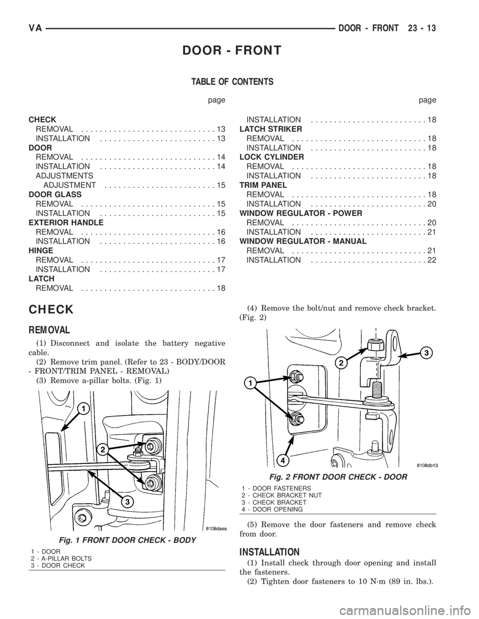
CHECK
REMOVAL
(1) Disconnect and isolate the battery negative
cable.
(2) Remove trim panel. (Refer to 23 - BODY/DOOR
- FRONT/TRIM PANEL - REMOVAL)
(3) Remove a-pillar bolts. (Fig. 1)(4) Remove the bolt/nut and remove check bracket.
(Fig. 2)
(5) Remove the door fasteners and remove check
from door.
INSTALLATION
(1) Install check through door opening and install
the fasteners.
(2) Tighten door fasteners to 10 N´m (89 in. lbs.).
Fig. 1 FRONT DOOR CHECK - BODY
1 - DOOR
2 - A-PILLAR BOLTS
3 - DOOR CHECK
Fig. 2 FRONT DOOR CHECK - DOOR
1 - DOOR FASTENERS
2 - CHECK BRACKET NUT
3 - CHECK BRACKET
4 - DOOR OPENING
VADOOR - FRONT 23 - 13
Page 1958 of 2305
(7) Install mirror. (Refer to 23 - BODY/EXTERI-
OR/SIDE VIEW MIRROR - INSTALLATION)
(8) Adjust door if required. (Refer to 23 - BODY/
DOOR - FRONT/DOOR - ADJUSTMENTS)
(9) Connect battery negative cable.
ADJUSTMENTS
ADJUSTMENT
NOTE: Door adjustment measurements should be
taken from stationary or welded body panels like
the roof, rocker or quarter panels.
²During adjustment procedures, it is recom-
mended that all the hinge fasteners be loosened
except for the upper most fasteners. Adjustments
can be made using the upper bolts to hold the door
with final torque of the fasteners occurring after
correct door positioning is achieved.
²A suitable body sealant should be used when
removing or moving the hinges.
(1) Check door alignment. (Refer to 23 - BODY/
BODY STRUCTURE/GAP AND FLUSH - SPECIFI-
CATIONS)
(2) If adjustment is required, remove latch striker.
(Refer to 23 - BODY/DOOR - FRONT/LATCH
STRIKER - REMOVAL)
(3) Remove side view mirror. (Refer to 23 - BODY/
EXTERIOR/SIDE VIEW MIRROR - REMOVAL)
(4) Loosen hinge bolts and adjust door gap and
align ridge pattern as necessary.
(5) Tighten hinge bolts to 25 N´m (18 ft. lbs.).
(6) Install latch striker and adjust flush measure-
ment as necessary. (Refer to 23 - BODY/DOOR -
FRONT/LATCH STRIKER - INSTALLATION)
(7) Install side view mirror. (Refer to 23 - BODY/
EXTERIOR/SIDE VIEW MIRROR - INSTALLA-
TION)
DOOR GLASS
REMOVAL
(1) Remove the regulator. (Refer to 23 - BODY/
DOOR - FRONT/WINDOW REGULATOR - POWER
or MANUAL - REMOVAL)
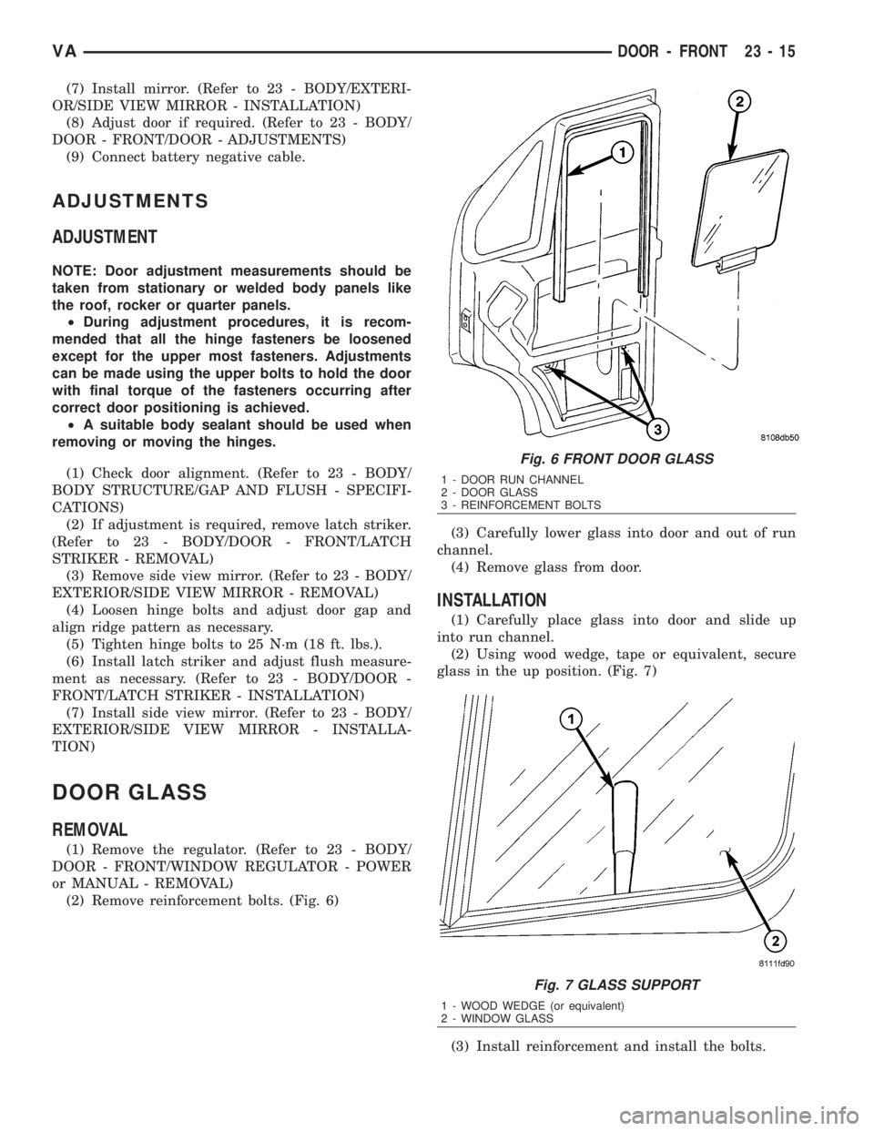
(2) Remove reinforcement bolts. (Fig. 6)(3) Carefully lower glass into door and out of run
channel.
(4) Remove glass from door.
INSTALLATION
(1) Carefully place glass into door and slide up
into run channel.
(2) Using wood wedge, tape or equivalent, secure
glass in the up position. (Fig. 7)
(3) Install reinforcement and install the bolts.
Fig. 6 FRONT DOOR GLASS
1 - DOOR RUN CHANNEL
2 - DOOR GLASS
3 - REINFORCEMENT BOLTS
Fig. 7 GLASS SUPPORT
1 - WOOD WEDGE (or equivalent)
2 - WINDOW GLASS
VADOOR - FRONT 23 - 15