2006 MERCEDES-BENZ SPRINTER engine
[x] Cancel search: enginePage 1047 of 2305
other minor debris from the outside windshield glass
surface that might be encountered while driving the
vehicle under numerous types of inclement operating
conditions.
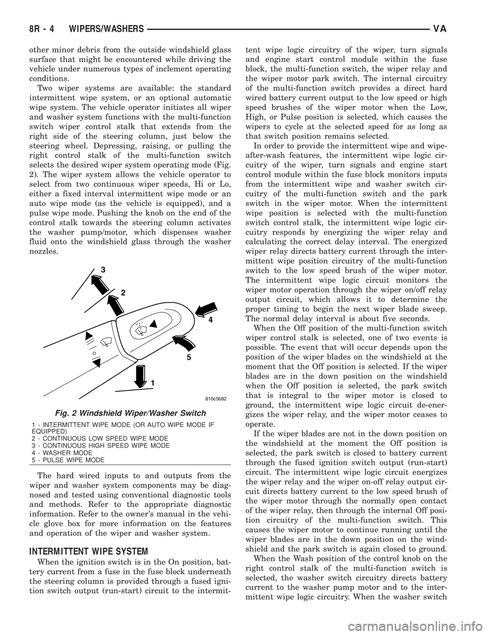
Two wiper systems are available: the standard
intermittent wipe system, or an optional automatic
wipe system. The vehicle operator initiates all wiper
and washer system functions with the multi-function
switch wiper control stalk that extends from the
right side of the steering column, just below the
steering wheel. Depressing, raising, or pulling the
right control stalk of the multi-function switch
selects the desired wiper system operating mode (Fig.
2). The wiper system allows the vehicle operator to
select from two continuous wiper speeds, Hi or Lo,
either a fixed interval intermittent wipe mode or an
auto wipe mode (as the vehicle is equipped), and a
pulse wipe mode. Pushing the knob on the end of the
control stalk towards the steering column activates
the washer pump/motor, which dispenses washer
fluid onto the windshield glass through the washer
nozzles.
The hard wired inputs to and outputs from the
wiper and washer system components may be diag-
nosed and tested using conventional diagnostic tools
and methods. Refer to the appropriate diagnostic
information. Refer to the owner's manual in the vehi-
cle glove box for more information on the features
and operation of the wiper and washer system.
INTERMITTENT WIPE SYSTEM
When the ignition switch is in the On position, bat-
tery current from a fuse in the fuse block underneath
the steering column is provided through a fused igni-
tion switch output (run-start) circuit to the intermit-tent wipe logic circuitry of the wiper, turn signals
and engine start control module within the fuse
block, the multi-function switch, the wiper relay and
the wiper motor park switch. The internal circuitry
of the multi-function switch provides a direct hard
wired battery current output to the low speed or high
speed brushes of the wiper motor when the Low,
High, or Pulse position is selected, which causes the
wipers to cycle at the selected speed for as long as
that switch position remains selected.
In order to provide the intermittent wipe and wipe-
after-wash features, the intermittent wipe logic cir-
cuitry of the wiper, turn signals and engine start
control module within the fuse block monitors inputs
from the intermittent wipe and washer switch cir-
cuitry of the multi-function switch and the park
switch in the wiper motor. When the intermittent
wipe position is selected with the multi-function
switch control stalk, the intermittent wipe logic cir-
cuitry responds by energizing the wiper relay and
calculating the correct delay interval. The energized
wiper relay directs battery current through the inter-
mittent wipe position circuitry of the multi-function
switch to the low speed brush of the wiper motor.
The intermittent wipe logic circuit monitors the
wiper motor operation through the wiper on/off relay
output circuit, which allows it to determine the
proper timing to begin the next wiper blade sweep.
The normal delay interval is about five seconds.
When the Off position of the multi-function switch
wiper control stalk is selected, one of two events is
possible. The event that will occur depends upon the
position of the wiper blades on the windshield at the
moment that the Off position is selected. If the wiper
blades are in the down position on the windshield
when the Off position is selected, the park switch
that is integral to the wiper motor is closed to
ground, the intermittent wipe logic circuit de-ener-
gizes the wiper relay, and the wiper motor ceases to
operate.
If the wiper blades are not in the down position on
the windshield at the moment the Off position is
selected, the park switch is closed to battery current
through the fused ignition switch output (run-start)
circuit. The intermittent wipe logic circuit energizes
the wiper relay and the wiper on-off relay output cir-
cuit directs battery current to the low speed brush of
the wiper motor through the normally open contact
of the wiper relay, then through the internal Off posi-
tion circuitry of the multi-function switch. This
causes the wiper motor to continue running until the
wiper blades are in the down position on the wind-
shield and the park switch is again closed to ground.
When the Wash position of the control knob on the
right control stalk of the multi-function switch is
selected, the washer switch circuitry directs battery
current to the washer pump motor and to the inter-
mittent wipe logic circuitry. When the washer switch
Fig. 2 Windshield Wiper/Washer Switch
1 - INTERMITTENT WIPE MODE (OR AUTO WIPE MODE IF
EQUIPPED)
2 - CONTINUOUS LOW SPEED WIPE MODE
3 - CONTINUOUS HIGH SPEED WIPE MODE
4 - WASHER MODE
5 - PULSE WIPE MODE
8R - 4 WIPERS/WASHERSVA
Page 1048 of 2305
is closed with the wiper system turned Off, the inter-
mittent wipe logic circuitry operates the wiper motor
in the same manner as it does to provide the inter-
mittent wipe mode operation. After the state of the
washer switch changes to open, the intermittent wipe
logic circuitry monitors the wiper motor through the
wiper on-off relay output circuit, which allows it to
monitor the number of wiper blade sweeps. After the
appropriate number of wiper sweeps the intermittent
wipe logic circuitry operates the wiper motor to
return the wipers to their park position, then de-en-
ergizes the wiper relay.
AUTOMATIC WIPE SYSTEM
When the ignition switch is in the On position, bat-
tery current from a fuse in the fuse block underneath
the steering column is provided through a fused igni-
tion switch output (run-start) circuit to the rain sen-
sor control module under the instrument panel, to
the rain sensor within the base of the inside rear
view mirror on the windshield, and to the multi-func-
tion switch. The internal circuitry of the multi-func-
tion switch provides direct hard wired battery
current outputs to the rain sensor control module to
indicate the selected wiper operating mode. The con-
trol module logic monitors the inputs from the multi-
function switch as well as from the rain sensor and
the wiper motor park switch in order to provide the
outputs necessary to operate the wiper motor and the
washer pump motor as requested.
When the automatic wipe position is selected with
the multi-function switch control stalk, the rain sen-
sor control module logic circuitry responds by provid-
ing an acknowledgment sweep of the wipers. The
rain sensor calculates the correct wiper speed and
wiper sweep intervals required to remove the mois-
ture detected on the windshield glass and provides
this input to the rain sensor control module. The con-
trol module then energizes and de-energizes the
wiper motor automatically. The automatic wipe logic
will also provide a wipe-after-wash feature to clear
washer fluid that is directed onto the windshield
when the washer system is utilized.
When the Off position of the multi-function switch
wiper control stalk is selected, one of two events is
possible. The event that will occur depends upon the
position of the wiper blades on the windshield at the
moment that the Off position is selected. If the wiper
blades are in the down position on the windshield
when the Off position is selected, the park switch
that is integral to the wiper motor is closed to
ground, and the rain sensor control module logic cir-
cuit de-energizes the wiper motor. If the wiper blades
are not in the down position at the moment the Off
position is selected, the park switch is an open cir-
cuit. The control module logic circuit directs battery
current to the low speed brush of the wiper motor,
which causes the wiper motor to continue runninguntil the wiper blades are in the down position on
the windshield and the park switch is again closed to
ground.
When the Wash position of the control knob on the
right control stalk of the multi-function switch is
selected with the wiper system turned Off, the rain
sensor control module logic circuitry operates the
wiper motor in the same manner as it does to provide
the automatic wipe mode operation. After the state of
the washer switch changes to open the control mod-
ule monitors the wiper motor through the wiper park
switch sense circuit, which allows it to monitor the
number of wiper blade sweeps. After the appropriate
number of wiper sweeps the control module operates
the wiper motor to return the wipers to their park
position, then de-energizes the wiper motor.
OPERATING MODES
The components of the wiper and washer system
are designed to provide the following operating
modes:
²Automatic Wipe Mode- On vehicles so
equipped, the internal circuitry of the multi-function
switch, the rain sensor control module and the rain
sensor work in concert to provide wiper system oper-
ation automatically whenever moisture is detected on
the windshield glass.
²Continuous Wipe Mode- The two-speed wiper
motor, the internal circuitry of the multi-function
switch, and the wiper system logic circuits work in
concert to provide two continuous wipe cycles, low
speed or high speed.
²Intermittent Wipe Mode- On vehicles so
equipped, the internal circuitry of the multi-function
switch, the intermittent wipe circuitry of the wiper,
turn signals and engine start control module in the
fuse block, and the wiper relay work in concert to
provide an intermittent wipe mode with a single,
fixed delay interval.
²Pulse Wipe Mode- The internal circuitry of
the multi-function switch and the wiper system logic
circuits work in concert to provide a pulse wipe mode
that will allow the wiper motor to be operated for a
single, complete wipe cycle.
²Washer Mode- When the washer system is
activated with the multi-function switch while the
wiper system is operating, washer fluid will be dis-
pensed onto the windshield glass through the washer
nozzles for as long as the washer pump/motor is
energized.
²Wipe-After-Wash Mode- The wiper system
logic circuitry provides a wipe-after-wash feature. If
the wipers are turned Off, this feature will operate
the washer pump/motor and the wipers for as long as
the washer system is activated, then provide several
additional wipe cycles after the washer system is
deactivated before parking the wiper blades near the
base of the windshield.
VAWIPERS/WASHERS 8R - 5
Page 1054 of 2305
CHECK VALVE
DESCRIPTION
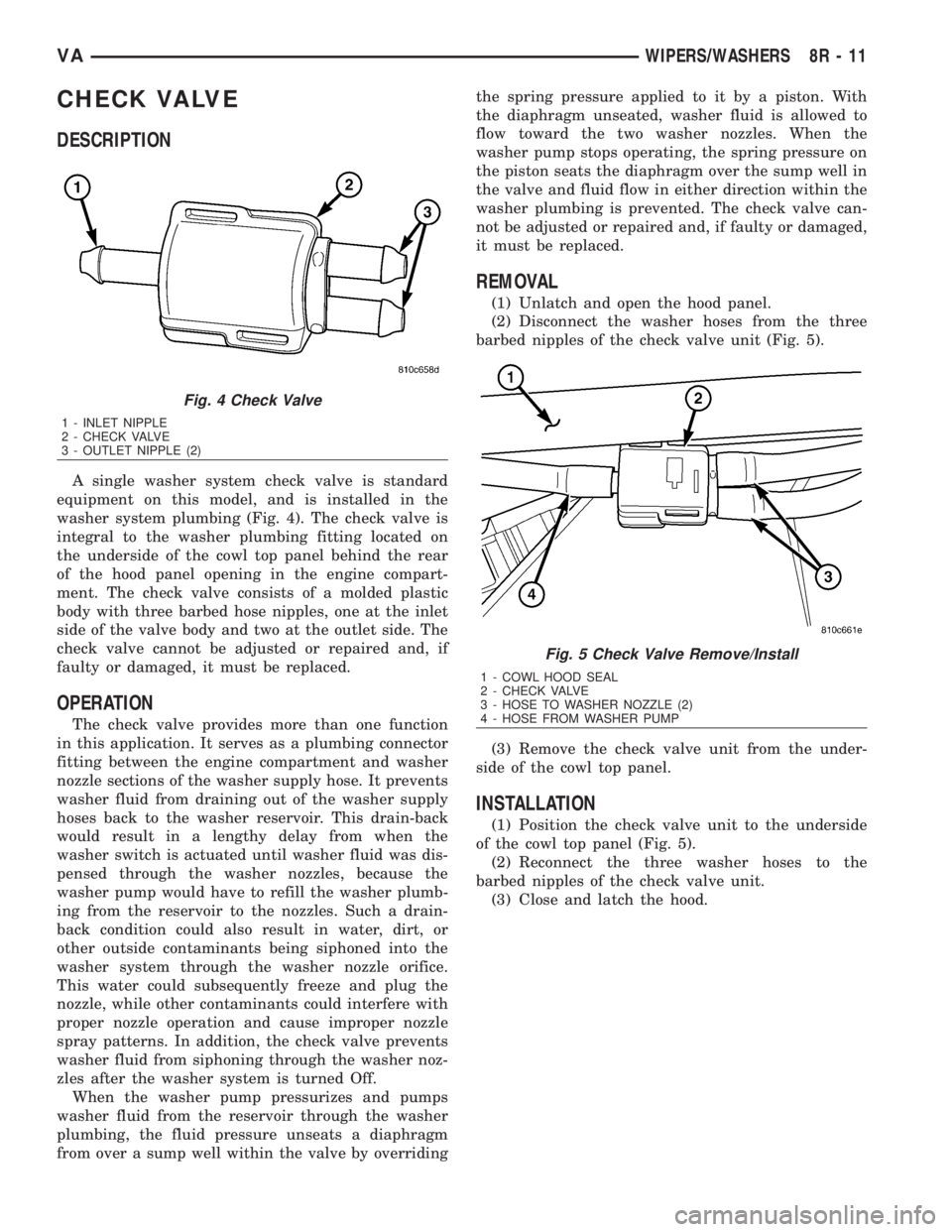
A single washer system check valve is standard
equipment on this model, and is installed in the
washer system plumbing (Fig. 4). The check valve is
integral to the washer plumbing fitting located on
the underside of the cowl top panel behind the rear
of the hood panel opening in the engine compart-
ment. The check valve consists of a molded plastic
body with three barbed hose nipples, one at the inlet
side of the valve body and two at the outlet side. The
check valve cannot be adjusted or repaired and, if
faulty or damaged, it must be replaced.
OPERATION
The check valve provides more than one function
in this application. It serves as a plumbing connector
fitting between the engine compartment and washer
nozzle sections of the washer supply hose. It prevents
washer fluid from draining out of the washer supply
hoses back to the washer reservoir. This drain-back
would result in a lengthy delay from when the
washer switch is actuated until washer fluid was dis-
pensed through the washer nozzles, because the
washer pump would have to refill the washer plumb-
ing from the reservoir to the nozzles. Such a drain-
back condition could also result in water, dirt, or
other outside contaminants being siphoned into the
washer system through the washer nozzle orifice.
This water could subsequently freeze and plug the
nozzle, while other contaminants could interfere with
proper nozzle operation and cause improper nozzle
spray patterns. In addition, the check valve prevents
washer fluid from siphoning through the washer noz-
zles after the washer system is turned Off.
When the washer pump pressurizes and pumps
washer fluid from the reservoir through the washer
plumbing, the fluid pressure unseats a diaphragm
from over a sump well within the valve by overridingthe spring pressure applied to it by a piston. With
the diaphragm unseated, washer fluid is allowed to
flow toward the two washer nozzles. When the
washer pump stops operating, the spring pressure on
the piston seats the diaphragm over the sump well in
the valve and fluid flow in either direction within the
washer plumbing is prevented. The check valve can-
not be adjusted or repaired and, if faulty or damaged,
it must be replaced.
REMOVAL
(1) Unlatch and open the hood panel.
(2) Disconnect the washer hoses from the three
barbed nipples of the check valve unit (Fig. 5).
(3) Remove the check valve unit from the under-
side of the cowl top panel.
INSTALLATION
(1) Position the check valve unit to the underside
of the cowl top panel (Fig. 5).
(2) Reconnect the three washer hoses to the
barbed nipples of the check valve unit.
(3) Close and latch the hood.
Fig. 4 Check Valve
1 - INLET NIPPLE
2 - CHECK VALVE
3 - OUTLET NIPPLE (2)
Fig. 5 Check Valve Remove/Install
1 - COWL HOOD SEAL
2 - CHECK VALVE
3 - HOSE TO WASHER NOZZLE (2)
4 - HOSE FROM WASHER PUMP
VAWIPERS/WASHERS 8R - 11
Page 1059 of 2305
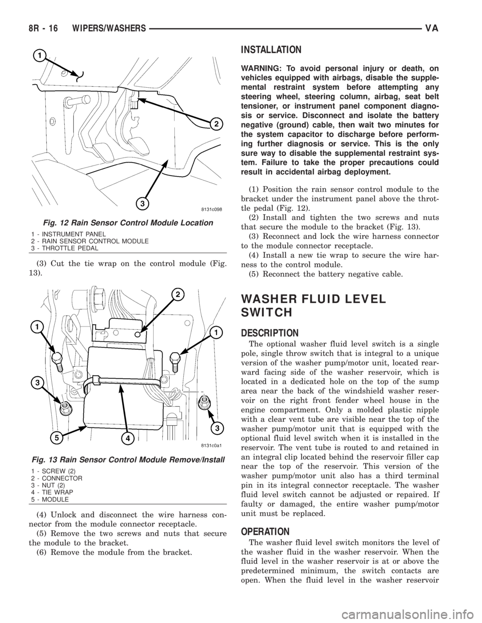
(3) Cut the tie wrap on the control module (Fig.
13).
(4) Unlock and disconnect the wire harness con-
nector from the module connector receptacle.
(5) Remove the two screws and nuts that secure
the module to the bracket.
(6) Remove the module from the bracket.
INSTALLATION
WARNING: To avoid personal injury or death, on
vehicles equipped with airbags, disable the supple-
mental restraint system before attempting any
steering wheel, steering column, airbag, seat belt
tensioner, or instrument panel component diagno-
sis or service. Disconnect and isolate the battery
negative (ground) cable, then wait two minutes for
the system capacitor to discharge before perform-
ing further diagnosis or service. This is the only
sure way to disable the supplemental restraint sys-
tem. Failure to take the proper precautions could
result in accidental airbag deployment.
(1) Position the rain sensor control module to the
bracket under the instrument panel above the throt-
tle pedal (Fig. 12).
(2) Install and tighten the two screws and nuts
that secure the module to the bracket (Fig. 13).
(3) Reconnect and lock the wire harness connector
to the module connector receptacle.
(4) Install a new tie wrap to secure the wire har-
ness to the control module.
(5) Reconnect the battery negative cable.
WASHER FLUID LEVEL
SWITCH
DESCRIPTION
The optional washer fluid level switch is a single
pole, single throw switch that is integral to a unique
version of the washer pump/motor unit, located rear-
ward facing side of the washer reservoir, which is
located in a dedicated hole on the top of the sump
area near the back of the windshield washer reser-
voir on the right front fender wheel house in the
engine compartment. Only a molded plastic nipple
with a clear vent tube are visible near the top of the
washer pump/motor unit that is equipped with the
optional fluid level switch when it is installed in the
reservoir. The vent tube is routed to and retained in
an integral clip located behind the reservoir filler cap
near the top of the reservoir. This version of the
washer pump/motor unit also has a third terminal
pin in its integral connector receptacle. The washer
fluid level switch cannot be adjusted or repaired. If
faulty or damaged, the entire washer pump/motor
unit must be replaced.
OPERATION
The washer fluid level switch monitors the level of
the washer fluid in the washer reservoir. When the
fluid level in the washer reservoir is at or above the
predetermined minimum, the switch contacts are
open. When the fluid level in the washer reservoir
Fig. 12 Rain Sensor Control Module Location
1 - INSTRUMENT PANEL
2 - RAIN SENSOR CONTROL MODULE
3 - THROTTLE PEDAL
Fig. 13 Rain Sensor Control Module Remove/Install
1 - SCREW (2)
2 - CONNECTOR
3 - NUT (2)
4 - TIE WRAP
5 - MODULE
8R - 16 WIPERS/WASHERSVA
Page 1060 of 2305
falls below the predetermined minimum, the switch
contacts of the normally open switch close. The
washer fluid level switch is connected to the vehicle
electrical system through the washer pump/motor
unit take out and connector of the vehicle wire har-
ness. The switch receives a path to ground at all
times through another take out of the vehicle wire
harness with a single eyelet terminal connector that
is secured under a ground screw located near the
right headlamp in the engine compartment.
The switch is connected in series between ground
and the washer fluid switch sense input to the Elec-
troMechanical Instrument Cluster (EMIC). When the
switch closes, the EMIC senses the ground on the
washer fluid switch sense circuit. The EMIC is pro-
grammed to respond to this input by illuminating the
washer fluid indicator. The washer fluid level switch
input to the EMIC may be diagnosed using conven-
tional diagnostic tools and methods.
VAWIPERS/WASHERS 8R - 17
Page 1061 of 2305
WASHER HOSES / TUBES
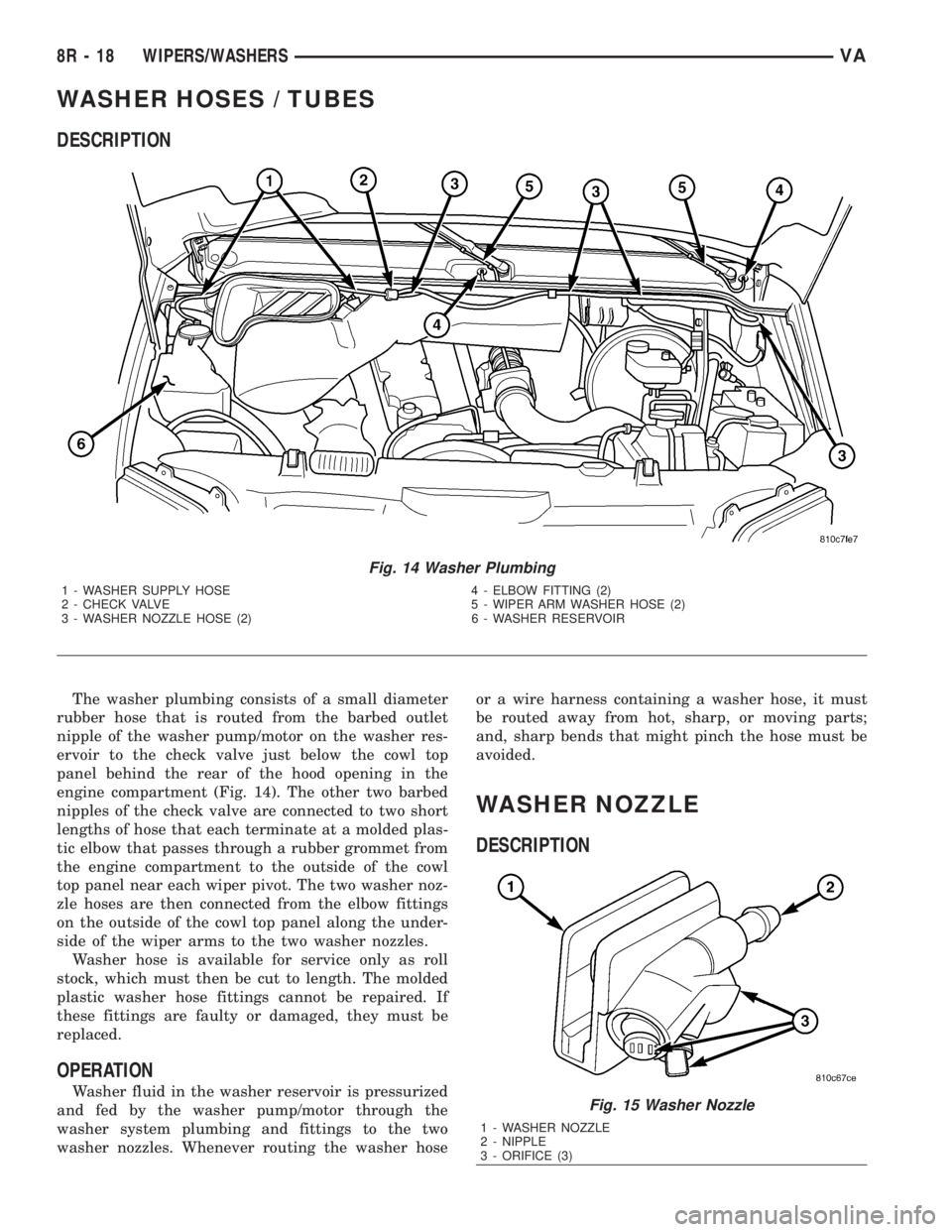
DESCRIPTION
The washer plumbing consists of a small diameter
rubber hose that is routed from the barbed outlet
nipple of the washer pump/motor on the washer res-
ervoir to the check valve just below the cowl top
panel behind the rear of the hood opening in the
engine compartment (Fig. 14). The other two barbed
nipples of the check valve are connected to two short
lengths of hose that each terminate at a molded plas-
tic elbow that passes through a rubber grommet from
the engine compartment to the outside of the cowl
top panel near each wiper pivot. The two washer noz-
zle hoses are then connected from the elbow fittings
on the outside of the cowl top panel along the under-
side of the wiper arms to the two washer nozzles.
Washer hose is available for service only as roll
stock, which must then be cut to length. The molded
plastic washer hose fittings cannot be repaired. If
these fittings are faulty or damaged, they must be
replaced.
OPERATION
Washer fluid in the washer reservoir is pressurized
and fed by the washer pump/motor through the
washer system plumbing and fittings to the two
washer nozzles. Whenever routing the washer hoseor a wire harness containing a washer hose, it must
be routed away from hot, sharp, or moving parts;
and, sharp bends that might pinch the hose must be
avoided.
WASHER NOZZLE
DESCRIPTION
Fig. 14 Washer Plumbing
1 - WASHER SUPPLY HOSE 4 - ELBOW FITTING (2)
2 - CHECK VALVE 5 - WIPER ARM WASHER HOSE (2)
3 - WASHER NOZZLE HOSE (2) 6 - WASHER RESERVOIR
Fig. 15 Washer Nozzle
1 - WASHER NOZZLE
2 - NIPPLE
3 - ORIFICE (3)
8R - 18 WIPERS/WASHERSVA
Page 1062 of 2305
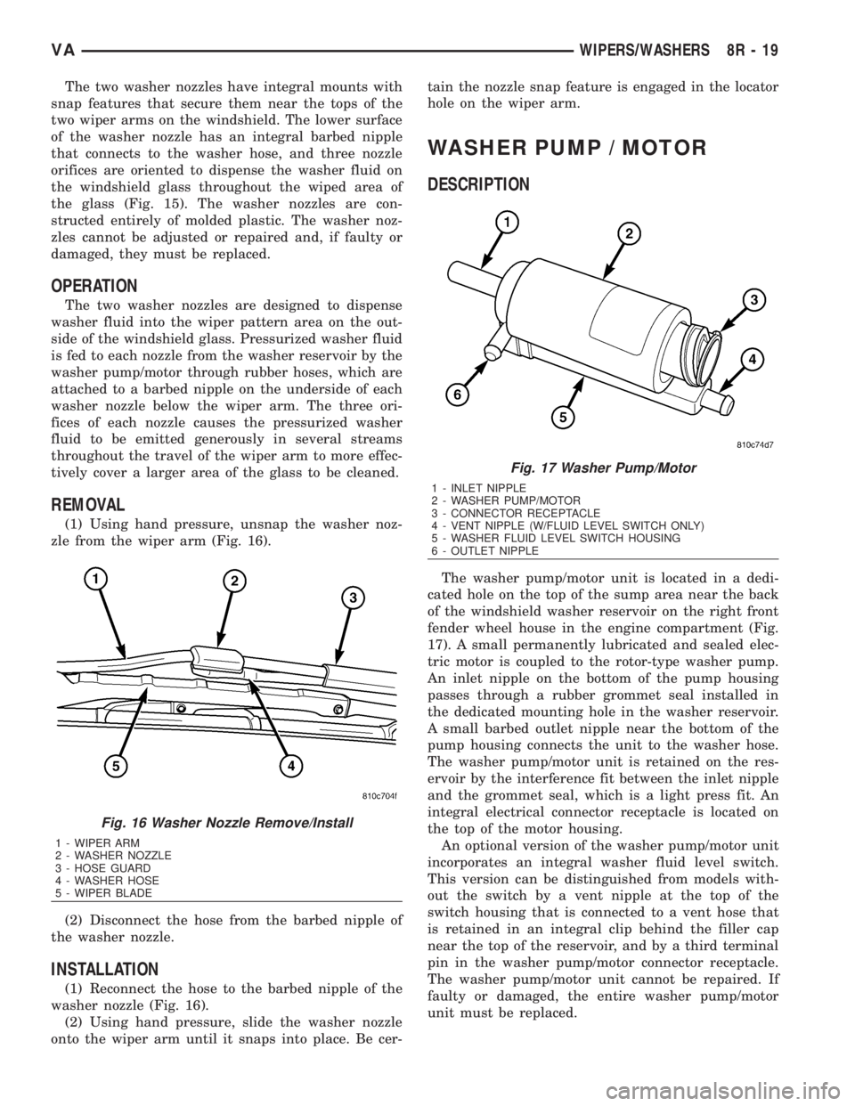
The two washer nozzles have integral mounts with
snap features that secure them near the tops of the
two wiper arms on the windshield. The lower surface
of the washer nozzle has an integral barbed nipple
that connects to the washer hose, and three nozzle
orifices are oriented to dispense the washer fluid on
the windshield glass throughout the wiped area of
the glass (Fig. 15). The washer nozzles are con-
structed entirely of molded plastic. The washer noz-
zles cannot be adjusted or repaired and, if faulty or
damaged, they must be replaced.
OPERATION
The two washer nozzles are designed to dispense
washer fluid into the wiper pattern area on the out-
side of the windshield glass. Pressurized washer fluid
is fed to each nozzle from the washer reservoir by the
washer pump/motor through rubber hoses, which are
attached to a barbed nipple on the underside of each
washer nozzle below the wiper arm. The three ori-
fices of each nozzle causes the pressurized washer
fluid to be emitted generously in several streams
throughout the travel of the wiper arm to more effec-
tively cover a larger area of the glass to be cleaned.
REMOVAL
(1) Using hand pressure, unsnap the washer noz-
zle from the wiper arm (Fig. 16).
(2) Disconnect the hose from the barbed nipple of
the washer nozzle.
INSTALLATION
(1) Reconnect the hose to the barbed nipple of the
washer nozzle (Fig. 16).
(2) Using hand pressure, slide the washer nozzle
onto the wiper arm until it snaps into place. Be cer-tain the nozzle snap feature is engaged in the locator
hole on the wiper arm.
WASHER PUMP / MOTOR
DESCRIPTION
The washer pump/motor unit is located in a dedi-
cated hole on the top of the sump area near the back
of the windshield washer reservoir on the right front
fender wheel house in the engine compartment (Fig.
17). A small permanently lubricated and sealed elec-
tric motor is coupled to the rotor-type washer pump.
An inlet nipple on the bottom of the pump housing
passes through a rubber grommet seal installed in
the dedicated mounting hole in the washer reservoir.
A small barbed outlet nipple near the bottom of the
pump housing connects the unit to the washer hose.
The washer pump/motor unit is retained on the res-
ervoir by the interference fit between the inlet nipple
and the grommet seal, which is a light press fit. An
integral electrical connector receptacle is located on
the top of the motor housing.
An optional version of the washer pump/motor unit
incorporates an integral washer fluid level switch.
This version can be distinguished from models with-
out the switch by a vent nipple at the top of the
switch housing that is connected to a vent hose that
is retained in an integral clip behind the filler cap
near the top of the reservoir, and by a third terminal
pin in the washer pump/motor connector receptacle.
The washer pump/motor unit cannot be repaired. If
faulty or damaged, the entire washer pump/motor
unit must be replaced.
Fig. 16 Washer Nozzle Remove/Install
1 - WIPER ARM
2 - WASHER NOZZLE
3 - HOSE GUARD
4 - WASHER HOSE
5 - WIPER BLADE
Fig. 17 Washer Pump/Motor
1 - INLET NIPPLE
2 - WASHER PUMP/MOTOR
3 - CONNECTOR RECEPTACLE
4 - VENT NIPPLE (W/FLUID LEVEL SWITCH ONLY)
5 - WASHER FLUID LEVEL SWITCH HOUSING
6 - OUTLET NIPPLE
VAWIPERS/WASHERS 8R - 19
Page 1063 of 2305

OPERATION
The washer pump/motor unit is connected to the
vehicle electrical system through a single take out
and connector of the vehicle wire harness. The
washer pump/motor is grounded at all times through
a take out of the vehicle wire harness with a single
eyelet terminal connector that is secured under a
ground screw located near the right headlamp in the
engine compartment. The washer pump/motor
receives battery current on a washer switch sense
circuit through the closed contacts of the momentary
washer switch circuitry within the multi-function
switch. When the pump motor is energized, the rotor-
type pump pressurizes the washer fluid and forces it
through the pump outlet nipple, the washer plumb-
ing, and the washer nozzles onto the windshield
glass. The washer pump/motor unit can be diagnosed
using conventional diagnostic tools and methods.
REMOVAL
(1) Disconnect the vehicle wire harness connector
for the washer pump/motor from the motor connector
receptacle (Fig. 18).
(2) Disconnect the washer supply hose from the
barbed outlet nipple of the washer pump/motor and
allow the washer fluid to drain into a clean container
for reuse.(3) If the vehicle is so equipped, disconnect the
washer fluid level switch vent hose from the barbed
vent nipple near the top of the washer pump/motor
unit.
(4) Using hand pressure, firmly grasp and pull the
washer pump out of the rubber grommet seal in the
reservoir. Care must be taken not to damage the res-
ervoir.
(5) Remove the rubber grommet seal from the
washer pump mounting hole in the washer reservoir
and discard.
INSTALLATION
(1) Install a new rubber grommet seal into the
washer pump mounting hole in the washer reservoir.
Always use a new rubber grommet seal on the reser-
voir.
(2) Position the inlet nipple of the washer pump to
the rubber grommet seal in the reservoir.
(3) Using hand pressure, press firmly and evenly
on the washer pump until the inlet nipple is fully
seated in the rubber grommet seal in the washer res-
ervoir mounting hole (Fig. 18).
(4) If the vehicle is so equipped, reconnect the
washer fluid level switch vent hose to the barbed
vent nipple at the top of the washer pump/motor
housing.
(5) Reconnect the washer hose to the barbed outlet
nipple of the washer pump.
(6) Reconnect the vehicle wire harness connector
for the washer pump/motor unit to the motor connec-
tor receptacle.
(7) Refill the washer reservoir with the washer
fluid drained from the reservoir during the removal
procedure.
Fig. 18 Washer Pump/Motor Remove/Install
1 - WASHER RESERVOIR
2 - WASHER SUPPLY HOSE
3 - VENT HOSE (W/FLUID LEVEL SWITCH ONLY)
4 - WIRE HARNESS CONNECTOR
5 - WASHER PUMP/MOTOR
8R - 20 WIPERS/WASHERSVA