2006 MERCEDES-BENZ SPRINTER relay
[x] Cancel search: relayPage 2166 of 2305
1.0 INTRODUCTION
The procedures contained in this manual include
all of the specifications, instructions, and graphics
needed to diagnose NAG1 Electronic Automatic
Transmission and Shift Lever Assembly problems.
The diagnostics in this manual are based on the
failure condition or symptom being present at the
time of diagnosis.
When repairs are required, refer to the appropri-
ate volume of the service information for the proper
removal and repair procedure.
READ THIS MANUAL BEFORE TRYING TO
DIAGNOSE A VEHICLE TROUBLE CODE.
Diagnostic procedures change every year. New
diagnostic systems may be added and/or carryover
systems may be enhanced. It is recommended that
you review the entire manual to become familiar
with all new and changed diagnostic procedures.
1.1 SYSTEM COVERAGE
This diagnostic procedures manual covers all
Sprinter (VA) equipped with a NAG1 Automatic
Transmission.
1.2 SIX -STEP TROUBLESHOOTING
PROCEDURE
Diagnosis of the NAG1 electronic transmission is
done in six basic steps:
Verification of complaint
Verification of any related symptoms
Symptom analysis
Problem isolation
Repair of isolated problem
Verification of proper operation
2.0 IDENTIFICATION OF
SYSTEM
The NAG1 Transmission family can be identified
by the presence of a 13 pin electrical connector, with
a bayonet lock on the right hand side of the trans-
mission. The connector is oriented horizontally.
3.0 SYSTEM DESCRIPTION AND
FUNCTIONAL OPERATION
3.1 GENERAL DESCRIPTION
The NAG1 electronic transmission is an electron-
ically controlled five speed transmission with a
controlled slip torque converter. The NAG1 elec-tronic transmission is a conventional transmission
in that it uses hydraulically applied clutches to shift
a planetary gear train. However, the electronic
control system replaces many of the mechanical and
hydraulic components used in conventional trans-
mission valve bodies.
The ratios for the gear stages are obtained by 3
planetary gear sets. Fifth Gear is designed as an
Overdrive with a high speed ratio. The gears are
actuated electronically/hydraulically. The electronic
control system enables precise adaptation of pres-
sures to the respective operating conditions and to
the engine output during a shift phase, which
results in a significant improvement in shift qual-
ity.
3.2 FUNCTIONAL OPERATION
The NAG1 electronic transmission has a fully
adaptive control system. The system performs its
functions based on continuous real-time sensor and
switch feedback information. In addition the TCM
receives information from the Shift Lever Assembly,
ECM (engine management) and ABS (chassis sys-
tems) controllers over the CAN bus. The CAN bus is
a high speed communication bus that allows real
time control capability between various controllers.
Most messages are sent every 20 milliseconds, this
means critical information can be shared between
the Transmission, Shifter, Engine and ABS control-
lers. The CAN bus is a two wire bus with aCAN C
Bus (+) circuitand aCAN C Bus (-) circuit. The
CAN bus uses a twisted pair of wires in the harness
to reduce the potential of radio and noise interfer-
ence. The CAN bus also uses a 120 ohm terminating
resistor in both the ECM and Sentry Key Remote
Entry Module (SKREEM) modules. The module
terminating resistance is measured across both
CAN bus circuits at the ECM or SKREEM module.
The control system automatically adapts to
changes in engine performance, vehicle speed, and
transmission temperature variations to provide
consistent shift quality. The control system ensures
that clutch operation during upshifting and down-
shifting is more responsive without increased
harshness. The TCM controls the actuation of sole-
noid valves for modulating shift pressure and gear
change. The required pressure level is calculated
from the load condition, engine speed. Power for the
transmission system is supplied through the Trans-
mission Relay. The TCM is located in the under the
drivers seat of the vehicle.
The Transmission Control Module (TCM) contin-
uously checks for electrical problems, mechanical
problems, and some hydraulic problems. When a
problem is sensed, the TCM stores a diagnostic
trouble code (DTC). Some of these codes cause the
transmission to go into9limp-in9or9default9mode.
1
GENERAL INFORMATION
Page 2186 of 2305
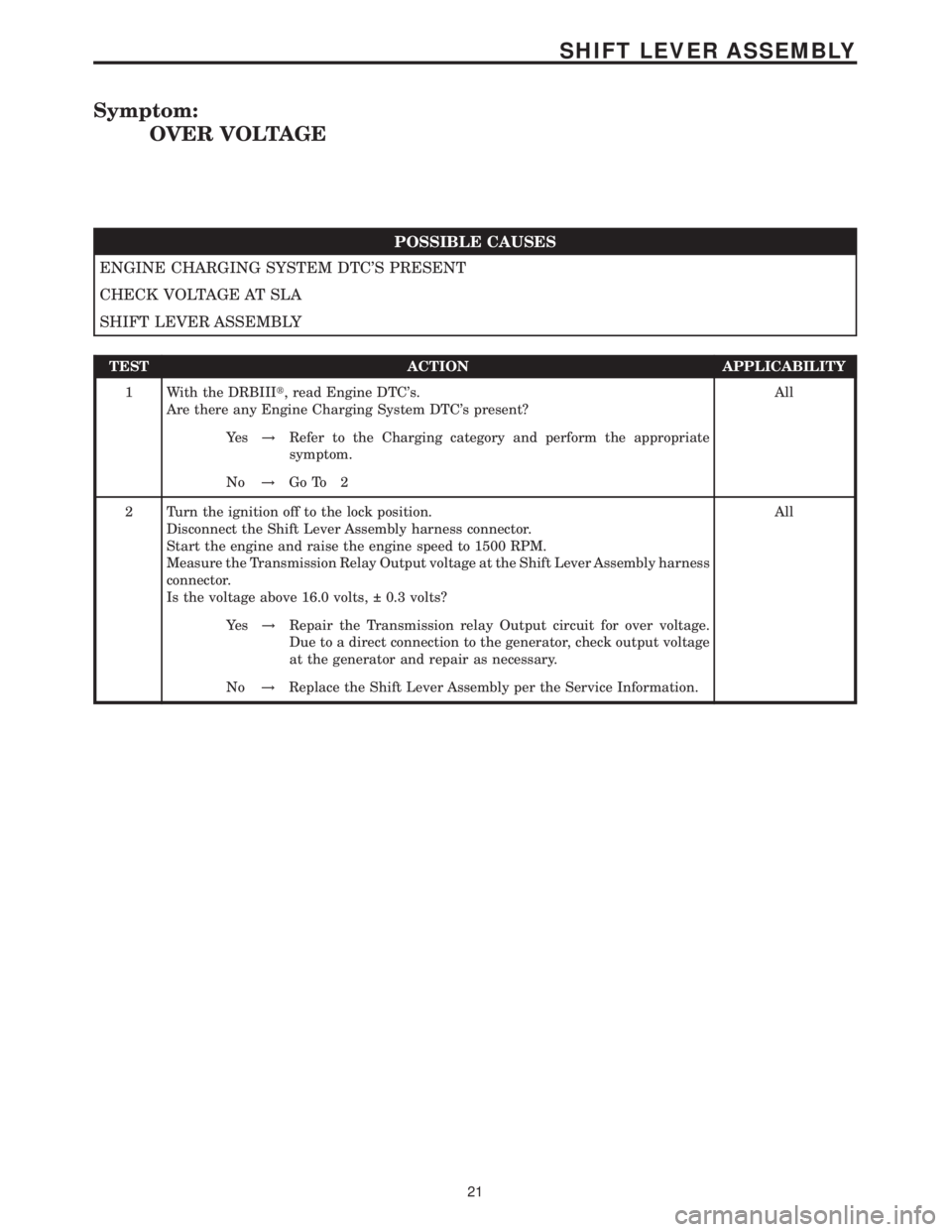
Symptom:
OVER VOLTAGE
POSSIBLE CAUSES
ENGINE CHARGING SYSTEM DTC'S PRESENT
CHECK VOLTAGE AT SLA
SHIFT LEVER ASSEMBLY
TEST ACTION APPLICABILITY
1 With the DRBIIIt, read Engine DTC's.
Are there any Engine Charging System DTC's present?All
Ye s!Refer to the Charging category and perform the appropriate
symptom.
No!Go To 2
2 Turn the ignition off to the lock position.
Disconnect the Shift Lever Assembly harness connector.
Start the engine and raise the engine speed to 1500 RPM.
Measure the Transmission Relay Output voltage at the Shift Lever Assembly harness
connector.
Is the voltage above 16.0 volts, 0.3 volts?All
Ye s!Repair the Transmission relay Output circuit for over voltage.
Due to a direct connection to the generator, check output voltage
at the generator and repair as necessary.
No!Replace the Shift Lever Assembly per the Service Information.
21
SHIFT LEVER ASSEMBLY
Page 2188 of 2305
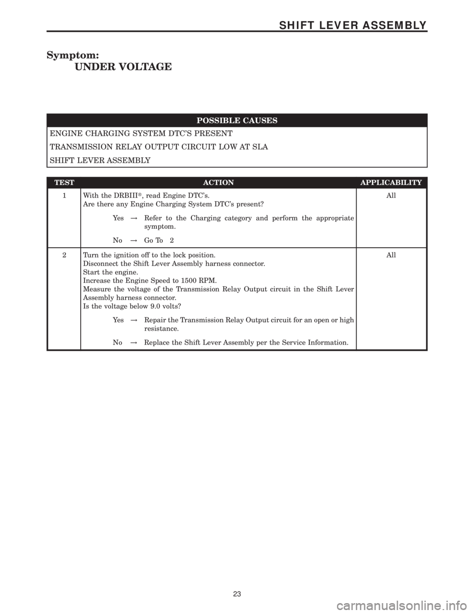
Symptom:
UNDER VOLTAGE
POSSIBLE CAUSES
ENGINE CHARGING SYSTEM DTC'S PRESENT
TRANSMISSION RELAY OUTPUT CIRCUIT LOW AT SLA
SHIFT LEVER ASSEMBLY
TEST ACTION APPLICABILITY
1 With the DRBIIIt, read Engine DTC's.
Are there any Engine Charging System DTC's present?All
Ye s!Refer to the Charging category and perform the appropriate
symptom.
No!Go To 2
2 Turn the ignition off to the lock position.
Disconnect the Shift Lever Assembly harness connector.
Start the engine.
Increase the Engine Speed to 1500 RPM.
Measure the voltage of the Transmission Relay Output circuit in the Shift Lever
Assembly harness connector.
Is the voltage below 9.0 volts?All
Ye s!Repair the Transmission Relay Output circuit for an open or high
resistance.
No!Replace the Shift Lever Assembly per the Service Information.
23
SHIFT LEVER ASSEMBLY
Page 2272 of 2305
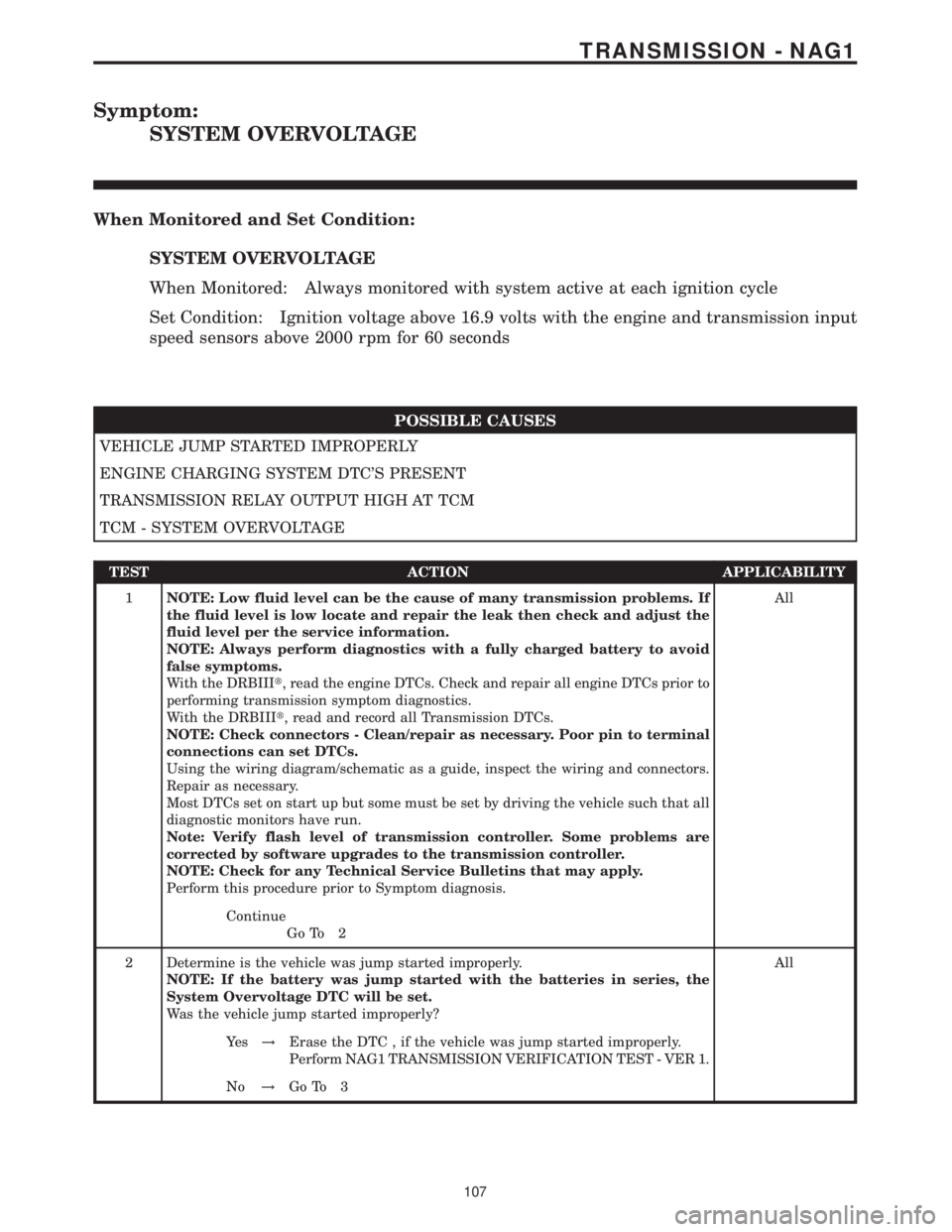
Symptom:
SYSTEM OVERVOLTAGE
When Monitored and Set Condition:
SYSTEM OVERVOLTAGE
When Monitored: Always monitored with system active at each ignition cycle
Set Condition: Ignition voltage above 16.9 volts with the engine and transmission input
speed sensors above 2000 rpm for 60 seconds
POSSIBLE CAUSES
VEHICLE JUMP STARTED IMPROPERLY
ENGINE CHARGING SYSTEM DTC'S PRESENT
TRANSMISSION RELAY OUTPUT HIGH AT TCM
TCM - SYSTEM OVERVOLTAGE
TEST ACTION APPLICABILITY
1NOTE: Low fluid level can be the cause of many transmission problems. If
the fluid level is low locate and repair the leak then check and adjust the
fluid level per the service information.
NOTE: Always perform diagnostics with a fully charged battery to avoid
false symptoms.
With the DRBIIIt, read the engine DTCs. Check and repair all engine DTCs prior to
performing transmission symptom diagnostics.
With the DRBIIIt, read and record all Transmission DTCs.
NOTE: Check connectors - Clean/repair as necessary. Poor pin to terminal
connections can set DTCs.
Using the wiring diagram/schematic as a guide, inspect the wiring and connectors.
Repair as necessary.
Most DTCs set on start up but some must be set by driving the vehicle such that all
diagnostic monitors have run.
Note: Verify flash level of transmission controller. Some problems are
corrected by software upgrades to the transmission controller.
NOTE: Check for any Technical Service Bulletins that may apply.
Perform this procedure prior to Symptom diagnosis.All
Continue
Go To 2
2 Determine is the vehicle was jump started improperly.
NOTE: If the battery was jump started with the batteries in series, the
System Overvoltage DTC will be set.
Was the vehicle jump started improperly?All
Ye s!Erase the DTC , if the vehicle was jump started improperly.
Perform NAG1 TRANSMISSION VERIFICATION TEST - VER 1.
No!Go To 3
107
TRANSMISSION - NAG1
Page 2273 of 2305
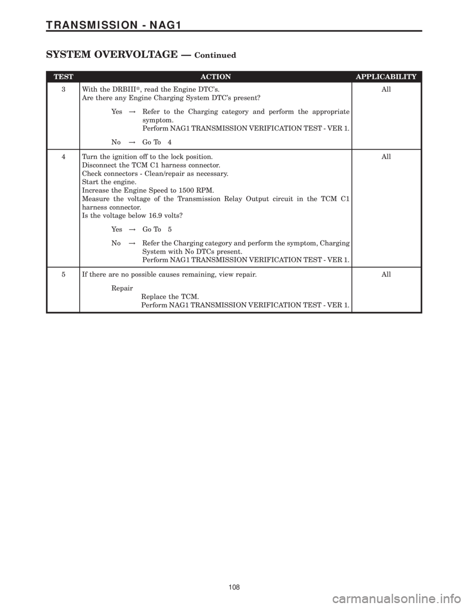
TEST ACTION APPLICABILITY
3 With the DRBIIIt, read the Engine DTC's.
Are there any Engine Charging System DTC's present?All
Ye s!Refer to the Charging category and perform the appropriate
symptom.
Perform NAG1 TRANSMISSION VERIFICATION TEST - VER 1.
No!Go To 4
4 Turn the ignition off to the lock position.
Disconnect the TCM C1 harness connector.
Check connectors - Clean/repair as necessary.
Start the engine.
Increase the Engine Speed to 1500 RPM.
Measure the voltage of the Transmission Relay Output circuit in the TCM C1
harness connector.
Is the voltage below 16.9 volts?All
Ye s!Go To 5
No!Refer the Charging category and perform the symptom, Charging
System with No DTCs present.
Perform NAG1 TRANSMISSION VERIFICATION TEST - VER 1.
5 If there are no possible causes remaining, view repair. All
Repair
Replace the TCM.
Perform NAG1 TRANSMISSION VERIFICATION TEST - VER 1.
108
TRANSMISSION - NAG1
SYSTEM OVERVOLTAGE ÐContinued
Page 2274 of 2305
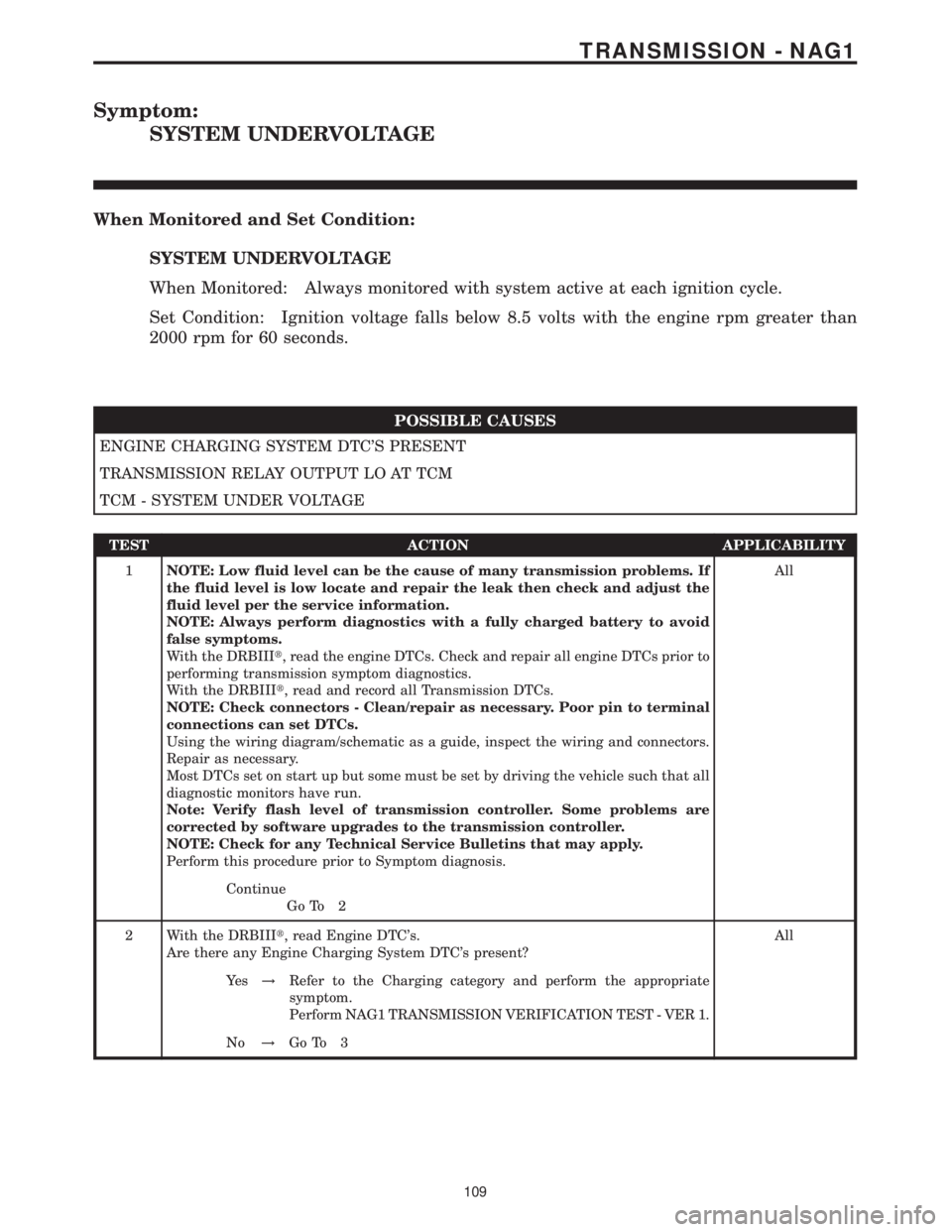
Symptom:
SYSTEM UNDERVOLTAGE
When Monitored and Set Condition:
SYSTEM UNDERVOLTAGE
When Monitored: Always monitored with system active at each ignition cycle.
Set Condition: Ignition voltage falls below 8.5 volts with the engine rpm greater than
2000 rpm for 60 seconds.
POSSIBLE CAUSES
ENGINE CHARGING SYSTEM DTC'S PRESENT
TRANSMISSION RELAY OUTPUT LO AT TCM
TCM - SYSTEM UNDER VOLTAGE
TEST ACTION APPLICABILITY
1NOTE: Low fluid level can be the cause of many transmission problems. If
the fluid level is low locate and repair the leak then check and adjust the
fluid level per the service information.
NOTE: Always perform diagnostics with a fully charged battery to avoid
false symptoms.
With the DRBIIIt, read the engine DTCs. Check and repair all engine DTCs prior to
performing transmission symptom diagnostics.
With the DRBIIIt, read and record all Transmission DTCs.
NOTE: Check connectors - Clean/repair as necessary. Poor pin to terminal
connections can set DTCs.
Using the wiring diagram/schematic as a guide, inspect the wiring and connectors.
Repair as necessary.
Most DTCs set on start up but some must be set by driving the vehicle such that all
diagnostic monitors have run.
Note: Verify flash level of transmission controller. Some problems are
corrected by software upgrades to the transmission controller.
NOTE: Check for any Technical Service Bulletins that may apply.
Perform this procedure prior to Symptom diagnosis.All
Continue
Go To 2
2 With the DRBIIIt, read Engine DTC's.
Are there any Engine Charging System DTC's present?All
Ye s!Refer to the Charging category and perform the appropriate
symptom.
Perform NAG1 TRANSMISSION VERIFICATION TEST - VER 1.
No!Go To 3
109
TRANSMISSION - NAG1
Page 2275 of 2305
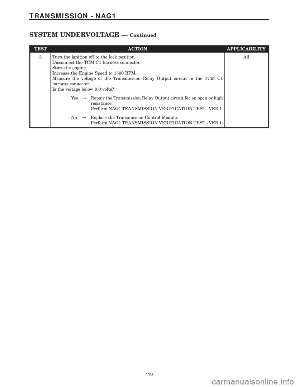
TEST ACTION APPLICABILITY
3 Turn the ignition off to the lock position.
Disconnect the TCM C1 harness connector.
Start the engine.
Increase the Engine Speed to 1500 RPM.
Measure the voltage of the Transmission Relay Output circuit in the TCM C1
harness connector.
Is the voltage below 9.0 volts?All
Ye s!Repair the Transmission Relay Output circuit for an open or high
resistance.
Perform NAG1 TRANSMISSION VERIFICATION TEST - VER 1.
No!Replace the Transmission Control Module.
Perform NAG1 TRANSMISSION VERIFICATION TEST - VER 1.
11 0
TRANSMISSION - NAG1
SYSTEM UNDERVOLTAGE ÐContinued
Page 2296 of 2305
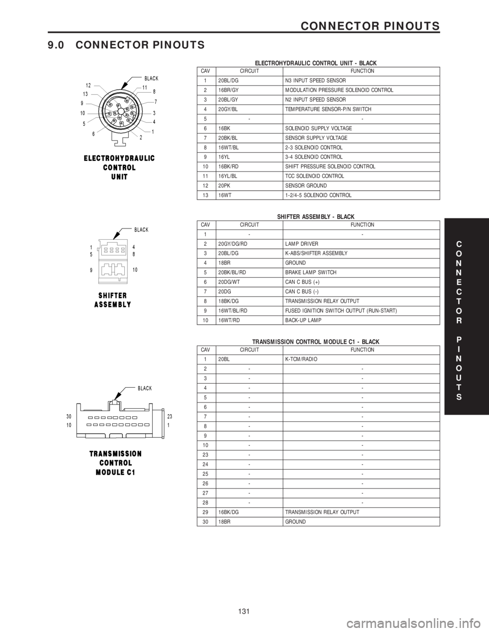
9.0 CONNECTOR PINOUTS
ELECTROHYDRAULIC CONTROL UNIT - BLACKCAV CIRCUIT FUNCTION
1 20BL/DG N3 INPUT SPEED SENSOR
2 16BR/GY MODULATION PRESSURE SOLENOID CONTROL
3 20BL/GY N2 INPUT SPEED SENSOR
4 20GY/BL TEMPERATURE SENSOR-P/N SWITCH
5- -
6 16BK SOLENOID SUPPLY VOLTAGE
7 20BK/BL SENSOR SUPPLY VOLTAGE
8 16WT/BL 2-3 SOLENOID CONTROL
9 16YL 3-4 SOLENOID CONTROL
10 16BK/RD SHIFT PRESSURE SOLENOID CONTROL
11 16YL/BL TCC SOLENOID CONTROL
12 20PK SENSOR GROUND
13 16WT 1-2/4-5 SOLENOID CONTROL
SHIFTER ASSEMBLY - BLACKCAV CIRCUIT FUNCTION
1- -
2 20GY/DG/RD LAMP DRIVER
3 20BL/DG K-ABS/SHIFTER ASSEMBLY
4 18BR GROUND
5 20BK/BL/RD BRAKE LAMP SWITCH
6 20DG/WT CAN C BUS (+)
7 20DG CAN C BUS (-)
8 18BK/DG TRANSMISSION RELAY OUTPUT
9 16WT/BL/RD FUSED IGNITION SWITCH OUTPUT (RUN-START)
10 16WT/RD BACK-UP LAMP
TRANSMISSION CONTROL MODULE C1 - BLACKCAV CIRCUIT FUNCTION
1 20BL K-TCM/RADIO
2- -
3- -
4- -
5- -
6- -
7- -
8- -
9- -
10 - -
23 - -
24 - -
25 - -
26 - -
27 - -
28 - -
29 16BK/DG TRANSMISSION RELAY OUTPUT
30 18BR GROUND
C
O
N
N
E
C
T
O
R
P
I
N
O
U
T
S
131
CONNECTOR PINOUTS