2006 MERCEDES-BENZ SPRINTER Fuel
[x] Cancel search: FuelPage 1729 of 2305
REMOVAL
(1) Disconnect the negative battery cable.
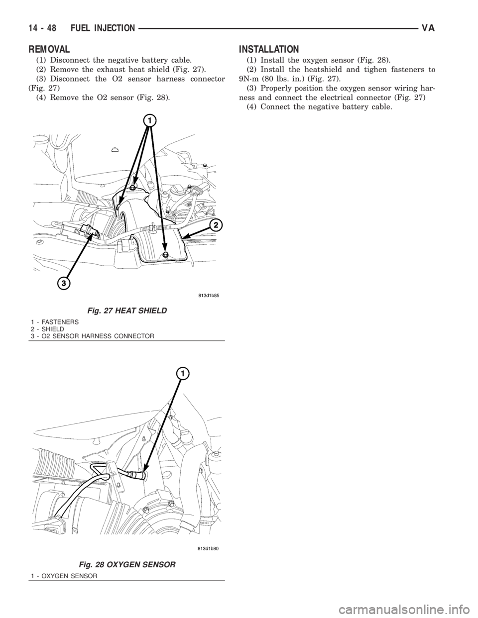
(2) Remove the exhaust heat shield (Fig. 27).
(3) Disconnect the O2 sensor harness connector
(Fig. 27)
(4) Remove the O2 sensor (Fig. 28).
INSTALLATION
(1) Install the oxygen sensor (Fig. 28).
(2) Install the heatshield and tighen fasteners to
9N´m (80 lbs. in.) (Fig. 27).
(3) Properly position the oxygen sensor wiring har-
ness and connect the electrical connector (Fig. 27)
(4) Connect the negative battery cable.
Fig. 27 HEAT SHIELD
1 - FASTENERS
2 - SHIELD
3 - O2 SENSOR HARNESS CONNECTOR
Fig. 28 OXYGEN SENSOR
1 - OXYGEN SENSOR
14 - 48 FUEL INJECTIONVA
Page 1746 of 2305
AUTOMATIC TRANSMISSION NAG1 - SERVICE INFORMATION
DESCRIPTION
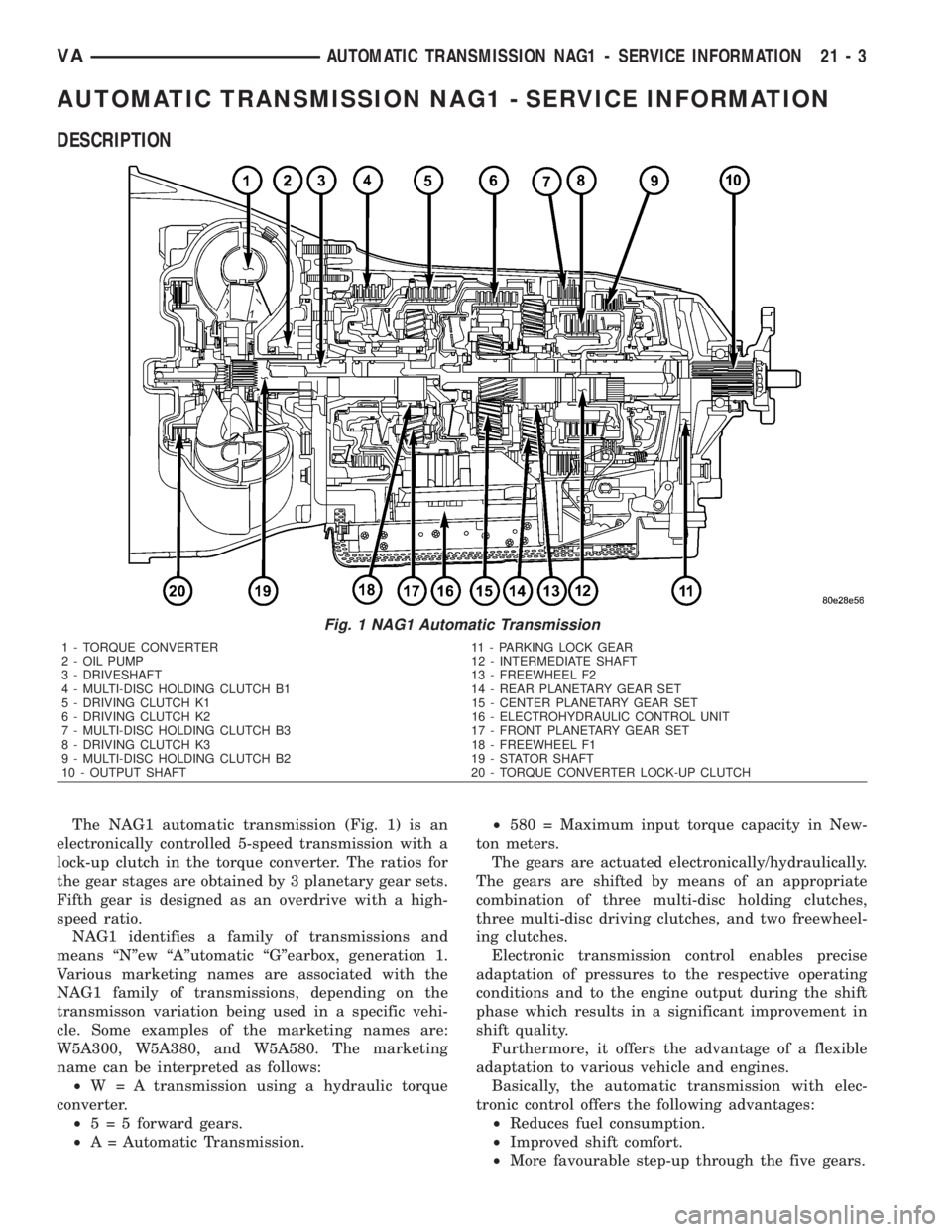
The NAG1 automatic transmission (Fig. 1) is an
electronically controlled 5-speed transmission with a
lock-up clutch in the torque converter. The ratios for
the gear stages are obtained by 3 planetary gear sets.
Fifth gear is designed as an overdrive with a high-
speed ratio.
NAG1 identifies a family of transmissions and
means ªNºew ªAºutomatic ªGºearbox, generation 1.
Various marketing names are associated with the
NAG1 family of transmissions, depending on the
transmisson variation being used in a specific vehi-
cle. Some examples of the marketing names are:
W5A300, W5A380, and W5A580. The marketing
name can be interpreted as follows:
²W = A transmission using a hydraulic torque
converter.
²5 = 5 forward gears.
²A = Automatic Transmission.²580 = Maximum input torque capacity in New-
ton meters.
The gears are actuated electronically/hydraulically.
The gears are shifted by means of an appropriate
combination of three multi-disc holding clutches,
three multi-disc driving clutches, and two freewheel-
ing clutches.
Electronic transmission control enables precise
adaptation of pressures to the respective operating
conditions and to the engine output during the shift
phase which results in a significant improvement in
shift quality.
Furthermore, it offers the advantage of a flexible
adaptation to various vehicle and engines.
Basically, the automatic transmission with elec-
tronic control offers the following advantages:
²Reduces fuel consumption.
²Improved shift comfort.
²More favourable step-up through the five gears.
Fig. 1 NAG1 Automatic Transmission
1 - TORQUE CONVERTER 11 - PARKING LOCK GEAR
2 - OIL PUMP 12 - INTERMEDIATE SHAFT
3 - DRIVESHAFT 13 - FREEWHEEL F2
4 - MULTI-DISC HOLDING CLUTCH B1 14 - REAR PLANETARY GEAR SET
5 - DRIVING CLUTCH K1 15 - CENTER PLANETARY GEAR SET
6 - DRIVING CLUTCH K2 16 - ELECTROHYDRAULIC CONTROL UNIT
7 - MULTI-DISC HOLDING CLUTCH B3 17 - FRONT PLANETARY GEAR SET
8 - DRIVING CLUTCH K3 18 - FREEWHEEL F1
9 - MULTI-DISC HOLDING CLUTCH B2 19 - STATOR SHAFT
10 - OUTPUT SHAFT 20 - TORQUE CONVERTER LOCK-UP CLUTCH
VAAUTOMATIC TRANSMISSION NAG1 - SERVICE INFORMATION 21 - 3
Page 1921 of 2305
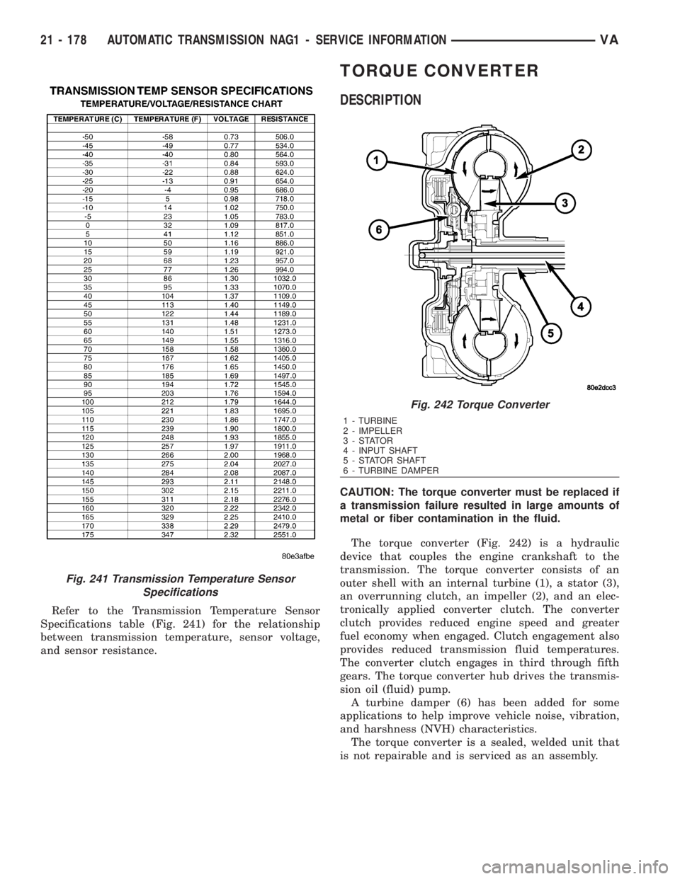
Refer to the Transmission Temperature Sensor
Specifications table (Fig. 241) for the relationship
between transmission temperature, sensor voltage,
and sensor resistance.
TORQUE CONVERTER
DESCRIPTION
CAUTION: The torque converter must be replaced if
a transmission failure resulted in large amounts of
metal or fiber contamination in the fluid.
The torque converter (Fig. 242) is a hydraulic
device that couples the engine crankshaft to the
transmission. The torque converter consists of an
outer shell with an internal turbine (1), a stator (3),
an overrunning clutch, an impeller (2), and an elec-
tronically applied converter clutch. The converter
clutch provides reduced engine speed and greater
fuel economy when engaged. Clutch engagement also
provides reduced transmission fluid temperatures.
The converter clutch engages in third through fifth
gears. The torque converter hub drives the transmis-
sion oil (fluid) pump.
A turbine damper (6) has been added for some
applications to help improve vehicle noise, vibration,
and harshness (NVH) characteristics.
The torque converter is a sealed, welded unit that
is not repairable and is serviced as an assembly.
Fig. 241 Transmission Temperature Sensor
Specifications
Fig. 242 Torque Converter
1 - TURBINE
2 - IMPELLER
3-STATOR
4 - INPUT SHAFT
5 - STATOR SHAFT
6 - TURBINE DAMPER
21 - 178 AUTOMATIC TRANSMISSION NAG1 - SERVICE INFORMATIONVA
Page 1935 of 2305
Radial-ply tires must always be used in sets of
four. Under no circumstances should they be used on
the front only. They may be mixed with temporary
spare tires when necessary. A maximum speed of 50
MPH is recommended while a temporary spare is in
use.
Radial-ply tires have the same load-carrying capac-
ity as other types of tires of the same size. They also
use the same recommended inflation pressures.
The use of oversized tires, either in the front or
rear of the vehicle, can cause vehicle drive train fail-
ure. This could also cause inaccurate wheel speed
signals when the vehicle is equipped with Anti-Lock
Brakes.
The use of tires from different manufactures on the
same vehicle is NOT recommended. The proper tire
pressure should be maintained on all four tires.
DESCRIPTION - TIRE PRESSURE FOR HIGH
SPEEDS
Where speed limits allow the vehicle to be driven
at high speeds, correct tire inflation pressure is very
important. For speeds up to and including 120 km/h
(75 mph), tires must be inflated to the pressures
shown on the tire placard. For continuous speeds in
excess of 120 km/h (75 mph), tires must be inflated
to the maximum pressure specified on the tire side-
wall.
Vehicles loaded to the maximum capacity should
not be driven at continuous speeds above 75 mph
(120 km/h).
For emergency vehicles that are driven at speeds
over 90 mph (144 km/h), special high speed tires
must be used. Consult tire manufacturer for correct
inflation pressure recommendations.
DESCRIPTION - REPLACEMENT TIRES
The original equipment tires provide a proper bal-
ance of many characteristics such as:
²Ride
²Noise
²Handling
²Durability
²Tread life
²Traction
²Rolling resistance
²Speed capability
It is recommended that tires equivalent to the orig-
inal equipment tires be used when replacement is
needed.
Failure to use equivalent replacement tires may
adversely affect the safety and handling of the vehi-
cle.The use of oversize tires may cause interference
with vehicle components. Under extremes of suspen-
sion and steering travel, interference with vehicle
components may cause tire damage.
WARNING: FAILURE TO EQUIP THE VEHICLE WITH
TIRES HAVING ADEQUATE SPEED CAPABILITY
CAN RESULT IN SUDDEN TIRE FAILURE.
DESCRIPTION - TIRE INFLATION PRESSURES
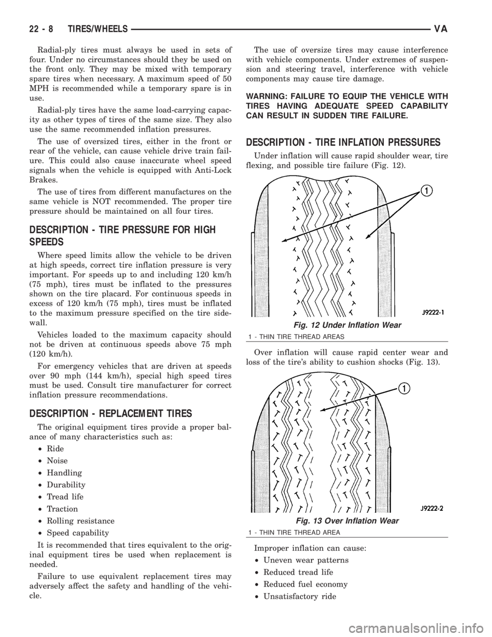
Under inflation will cause rapid shoulder wear, tire
flexing, and possible tire failure (Fig. 12).
Over inflation will cause rapid center wear and
loss of the tire's ability to cushion shocks (Fig. 13).
Improper inflation can cause:
²Uneven wear patterns
²Reduced tread life
²Reduced fuel economy
²Unsatisfactory ride
Fig. 12 Under Inflation Wear
1 - THIN TIRE THREAD AREAS
Fig. 13 Over Inflation Wear
1 - THIN TIRE THREAD AREA
22 - 8 TIRES/WHEELSVA
Page 1991 of 2305
EXTERIOR
TABLE OF CONTENTS
page page
FUEL FILL DOOR
REMOVAL.............................48
INSTALLATION.........................48
GRILLE
REMOVAL.............................48
INSTALLATION.........................48
LICENSE PLATE BRACKET
REMOVAL.............................48
INSTALLATION.........................48RADIATOR CROSSMEMBER
REMOVAL.............................49
INSTALLATION.........................49
SIDE VIEW MIRROR
REMOVAL.............................49
INSTALLATION.........................50
SIDE VIEW MIRROR - GLASS
REMOVAL.............................50
INSTALLATION.........................50
FUEL FILL DOOR
REMOVAL
(1) Open passenger compartment door.
(2) Open fuel fill door.
(3) Using a trim stick C-4755 or equivalent, dis-
connect the filler cap tether.
(4) Remove two bolts and remove filler door.
INSTALLATION
(1) Install the door and bolts.
(2) Connect filler cap tether.
(3) Close doors.
GRILLE
REMOVAL
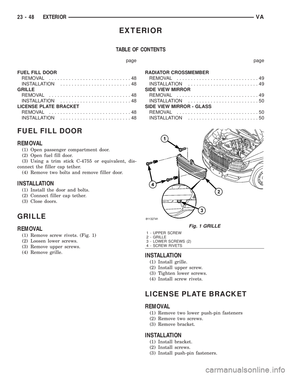
(1) Remove screw rivets. (Fig. 1)
(2) Loosen lower screws.
(3) Remove upper screws.
(4) Remove grille.
INSTALLATION
(1) Install grille.
(2) Install upper screw.
(3) Tighten lower screws.
(4) Install screw rivets.
LICENSE PLATE BRACKET
REMOVAL
(1) Remove two lower push-pin fasteners
(2) Remove two screws.
(3) Remove bracket.
INSTALLATION
(1) Install bracket.
(2) Install screws.
(3) Install push-pin fasteners.
Fig. 1 GRILLE
1 - UPPER SCREW
2 - GRILLE
3 - LOWER SCREWS (2)
4 - SCREW RIVETS
23 - 48 EXTERIORVA
Page 2137 of 2305
CAUTION: Use only the specified O-rings as they
are made of a special material for the R-134a sys-
tem. The use of any other O-rings may allow the
connection to leak intermittently during vehicle
operation.
(4) Lubricate the male fitting and O-rings, and the
inside of the female fitting with clean R-134a refrig-
erant oil. Use only refrigerant oil of the type recom-
mended for the compressor in the vehicle.
(5) Fit the female half of the coupler fitting over
the male half of the fitting.
(6) Push together firmly on the two halves of the
coupler fitting until the garter spring in the cage on
the male half of the fitting snaps over the flanged
end on the female half of the fitting.
(7) Ensure that the spring-lock coupler is fully
engaged by trying to separate the two coupler halves.
This is done by pulling the refrigerant lines on either
side of the coupler away from each other.
(8) Reinstall the secondary retaining clip over the
spring-lock coupler cage.
(9) Evacuate the refrigerant system (Refer to 24 -
HEATING & AIR CONDITIONING/PLUMBING -
STANDARD PROCEDURE - REFRIGERANT SYS-
TEM EVACUATE).
(10) Charge the refrigerant system (Refer to 24 -
HEATING & AIR CONDITIONING/PLUMBING -
STANDARD PROCEDURE - REFRIGERANT SYS-
TEM CHARGE).
UNDERBODY LINES
REMOVAL
WARNING: Refer to the applicable warnings and
cautions for this system before performing the fol-
lowing operation (Refer to 24 - HEATING & AIR
CONDITIONING/PLUMBING - WARNINGS) and (Refer
to 24 - HEATING & AIR CONDITIONING/PLUMBING -
CAUTIONS). Failure to follow the warnings and cau-
tions could result in possible personal injury or
death.
NOTE: The underbody refrigerant lines for the
optional rear A/C system are serviced in five sec-
tions. Two sections are connected the A/C compres-
sor. Two sections of the underbody suction line
(low-side) are connected together by a tapping
block with an O-ring seal. The underbody A/C dis-
charge line uses a spring-lock type refrigerant line
coupler with an O-ring seal.
DISCHARGE LINE
(1) Remove the cover from the rear A/C evaporator
housing (Refer to 24 - HEATING & AIR CONDI-TIONING/DISTRIBUTION - REAR/A/C EVAPORA-
TOR COVER-REAR - REMOVAL).
(2) Recover the refrigerant from the rear refriger-
ant system (Refer to 24 - HEATING & AIR CONDI-
TIONING/PLUMBING - STANDARD PROCEDURE -
REFRIGERANT RECOVERY).
(3) Raise and support the vehicle.
(4) Using the proper A/C line disconnect tool, dis-
connect the underbody discharge line spring-lock cou-
pler from the compressor section of the underbody
discharge line and remove and discard the O-ring
seal (Refer to 24 - HEATING & AIR CONDITION-
ING/PLUMBING/REFRIGERANT LINE COUPLER -
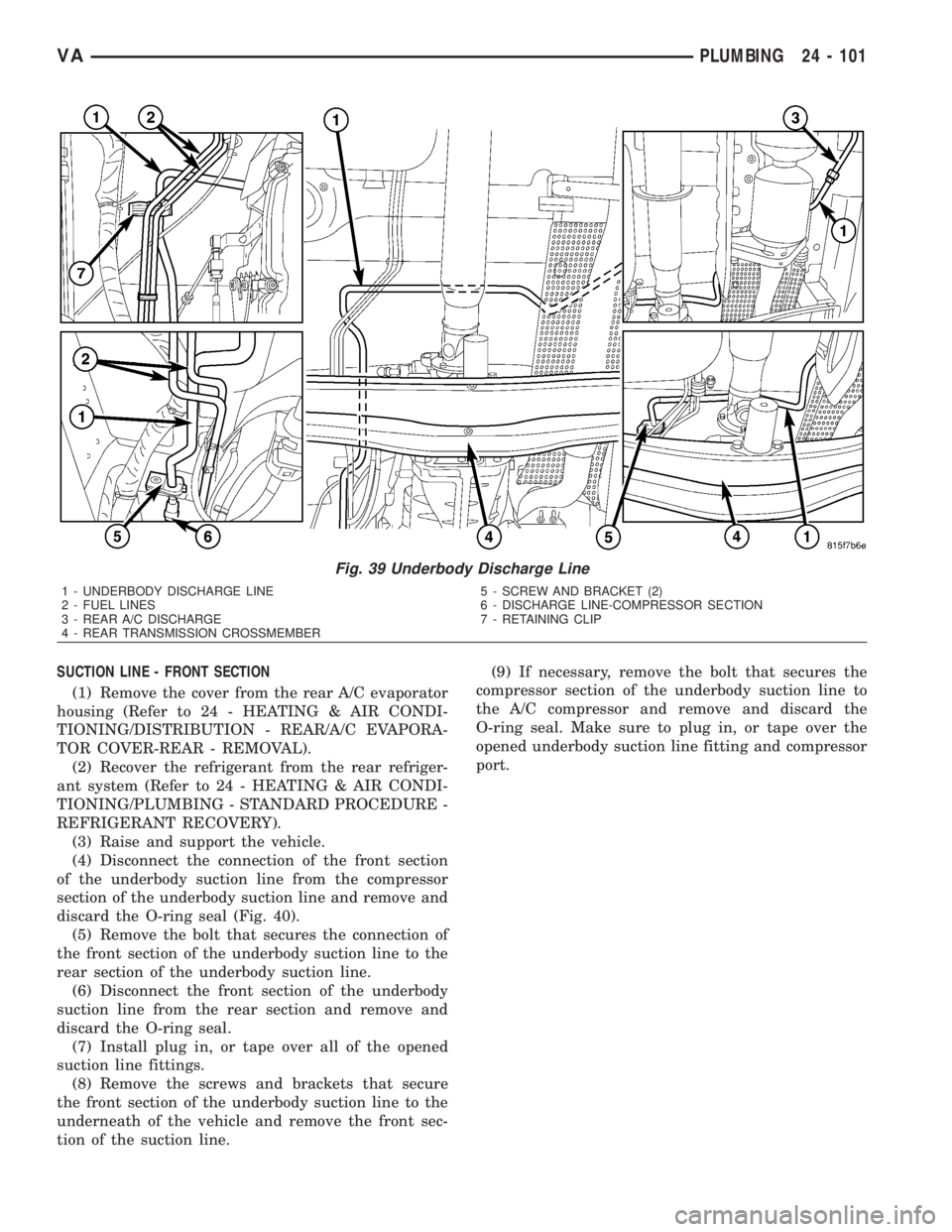
REMOVAL) (Fig. 39).
(5) Disconnect the underbody discharge line from
the rear A/C discharge line and remove and discard
the O-ring seal.
(6) Install plug in, or tape over all of the opened
discharge line fittings.
(7) Disengage the fuel lines from the retaining clip
located near the transmission and position the fuel
lines out of the way.
(8) Remove the screws and brackets that secure
the discharge line to the underneath of the vehicle.
(9) Support transmission with a suitable lifting
device and remove the rear transmission crossmem-
ber (Refer to 13 - FRAME & BUMPERS/FRAME/
REAR CROSSMEMBER-TRANSMISSION -
REMOVAL).
(10) Remove the underbody discharge line from
the vehicle. Push the discharge line forward and over
the transmission, then pull it rearward to remove.
(11) If necessary, remove the bolt that secures the
compressor section of the underbody discharge line to
the A/C compressor and remove and discard the
O-ring seal. Make sure to plug in, or tape over the
opened discharge line fitting and compressor port.
24 - 100 PLUMBINGVA
Page 2138 of 2305
SUCTION LINE - FRONT SECTION
(1) Remove the cover from the rear A/C evaporator
housing (Refer to 24 - HEATING & AIR CONDI-
TIONING/DISTRIBUTION - REAR/A/C EVAPORA-
TOR COVER-REAR - REMOVAL).
(2) Recover the refrigerant from the rear refriger-
ant system (Refer to 24 - HEATING & AIR CONDI-
TIONING/PLUMBING - STANDARD PROCEDURE -
REFRIGERANT RECOVERY).
(3) Raise and support the vehicle.
(4) Disconnect the connection of the front section
of the underbody suction line from the compressor
section of the underbody suction line and remove and
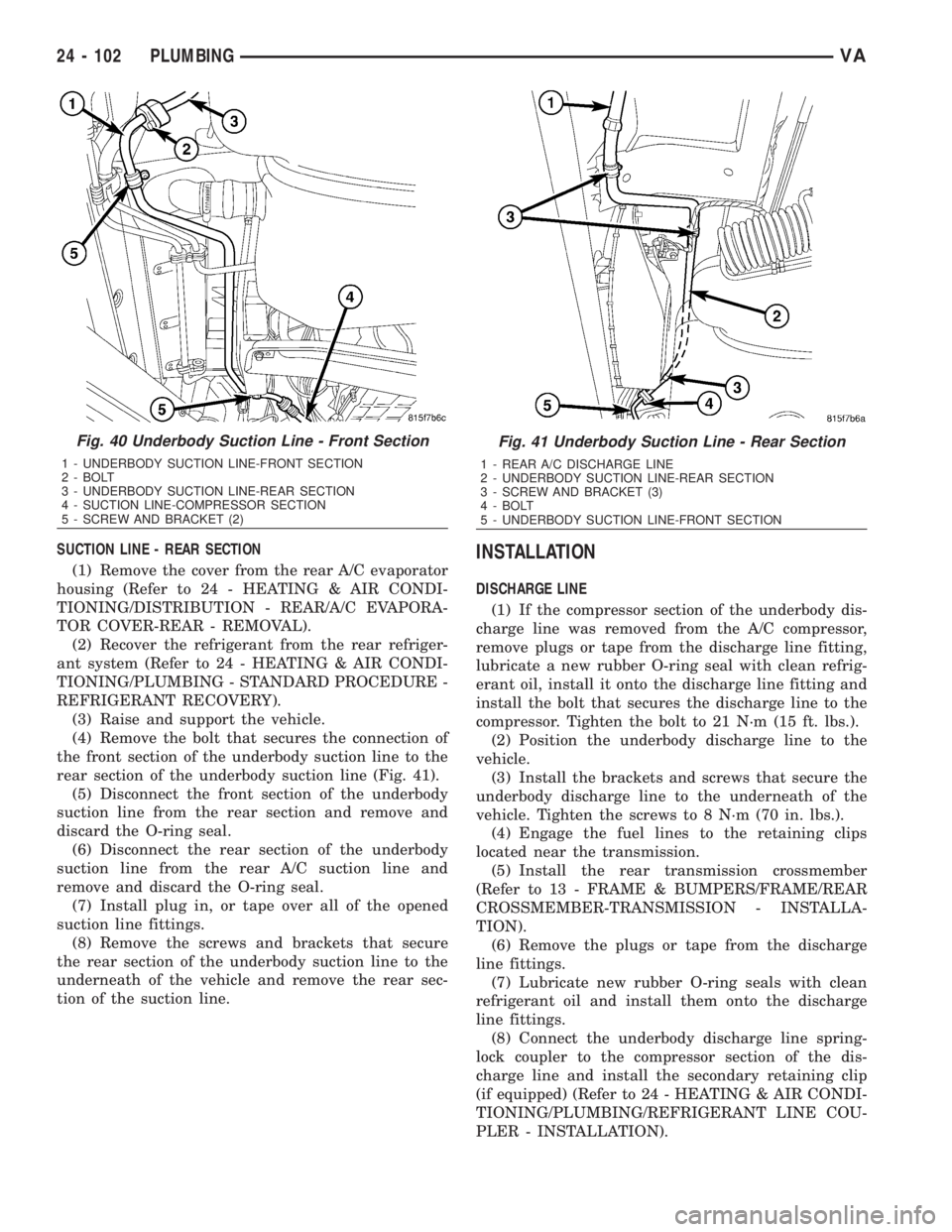
discard the O-ring seal (Fig. 40).
(5) Remove the bolt that secures the connection of
the front section of the underbody suction line to the
rear section of the underbody suction line.
(6) Disconnect the front section of the underbody
suction line from the rear section and remove and
discard the O-ring seal.
(7) Install plug in, or tape over all of the opened
suction line fittings.
(8) Remove the screws and brackets that secure
the front section of the underbody suction line to the
underneath of the vehicle and remove the front sec-
tion of the suction line.(9) If necessary, remove the bolt that secures the
compressor section of the underbody suction line to
the A/C compressor and remove and discard the
O-ring seal. Make sure to plug in, or tape over the
opened underbody suction line fitting and compressor
port.
Fig. 39 Underbody Discharge Line
1 - UNDERBODY DISCHARGE LINE
2 - FUEL LINES
3 - REAR A/C DISCHARGE
4 - REAR TRANSMISSION CROSSMEMBER5 - SCREW AND BRACKET (2)
6 - DISCHARGE LINE-COMPRESSOR SECTION
7 - RETAINING CLIP
VAPLUMBING 24 - 101
Page 2139 of 2305
SUCTION LINE - REAR SECTION
(1) Remove the cover from the rear A/C evaporator
housing (Refer to 24 - HEATING & AIR CONDI-
TIONING/DISTRIBUTION - REAR/A/C EVAPORA-
TOR COVER-REAR - REMOVAL).
(2) Recover the refrigerant from the rear refriger-
ant system (Refer to 24 - HEATING & AIR CONDI-
TIONING/PLUMBING - STANDARD PROCEDURE -
REFRIGERANT RECOVERY).
(3) Raise and support the vehicle.
(4) Remove the bolt that secures the connection of
the front section of the underbody suction line to the
rear section of the underbody suction line (Fig. 41).
(5) Disconnect the front section of the underbody
suction line from the rear section and remove and
discard the O-ring seal.
(6) Disconnect the rear section of the underbody
suction line from the rear A/C suction line and
remove and discard the O-ring seal.
(7) Install plug in, or tape over all of the opened
suction line fittings.
(8) Remove the screws and brackets that secure
the rear section of the underbody suction line to the
underneath of the vehicle and remove the rear sec-
tion of the suction line.INSTALLATION
DISCHARGE LINE
(1) If the compressor section of the underbody dis-
charge line was removed from the A/C compressor,
remove plugs or tape from the discharge line fitting,
lubricate a new rubber O-ring seal with clean refrig-
erant oil, install it onto the discharge line fitting and
install the bolt that secures the discharge line to the
compressor. Tighten the bolt to 21 N´m (15 ft. lbs.).
(2) Position the underbody discharge line to the
vehicle.
(3) Install the brackets and screws that secure the
underbody discharge line to the underneath of the
vehicle. Tighten the screws to 8 N´m (70 in. lbs.).
(4) Engage the fuel lines to the retaining clips
located near the transmission.
(5) Install the rear transmission crossmember
(Refer to 13 - FRAME & BUMPERS/FRAME/REAR
CROSSMEMBER-TRANSMISSION - INSTALLA-
TION).
(6) Remove the plugs or tape from the discharge
line fittings.
(7) Lubricate new rubber O-ring seals with clean
refrigerant oil and install them onto the discharge
line fittings.
(8) Connect the underbody discharge line spring-
lock coupler to the compressor section of the dis-
charge line and install the secondary retaining clip
(if equipped) (Refer to 24 - HEATING & AIR CONDI-
TIONING/PLUMBING/REFRIGERANT LINE COU-
PLER - INSTALLATION).
Fig. 40 Underbody Suction Line - Front Section
1 - UNDERBODY SUCTION LINE-FRONT SECTION
2 - BOLT
3 - UNDERBODY SUCTION LINE-REAR SECTION
4 - SUCTION LINE-COMPRESSOR SECTION
5 - SCREW AND BRACKET (2)
Fig. 41 Underbody Suction Line - Rear Section
1 - REAR A/C DISCHARGE LINE
2 - UNDERBODY SUCTION LINE-REAR SECTION
3 - SCREW AND BRACKET (3)
4 - BOLT
5 - UNDERBODY SUCTION LINE-FRONT SECTION
24 - 102 PLUMBINGVA