2006 MERCEDES-BENZ SPRINTER suspension
[x] Cancel search: suspensionPage 793 of 2305
As the dragging brake overheats, efficiency is so
reduced that fade occurs. Since the opposite brake
unit is still functioning normally, its braking effect is
magnified. This causes pull to switch direction in
favor of the normally functioning brake unit.
An additional point when diagnosing a change in
pull condition concerns brake cool down. Remember
that pull will return to the original direction, if the
dragging brake unit is allowed to cool down (and is
not seriously damaged).
REAR BRAKE GRAB OR PULL
Rear grab or pull is usually caused by improperly
adjusted or seized parking brake cables, contami-
nated lining, bent or binding shoes and support
plates, or improperly assembled components. This is
particularly true when only one rear wheel is
involved. However, when both rear wheels are
affected, the master cylinder or proportioning valve
could be at fault.
BRAKES DO NOT HOLD AFTER DRIVING THROUGH DEEP
WATER PUDDLES
This condition is generally caused by water soaked
lining. If the lining is only wet, it can be dried by
driving with the brakes very lightly applied for a
mile or two. However, if the lining is both soaked and
dirt contaminated, cleaning and/or replacement will
be necessary.
BRAKE LINING CONTAMINATION
Brake lining contamination is mostly a product of
leaking calipers or worn seals, driving through deep
water puddles, or lining that has become covered
with grease and grit during repair. Contaminated lin-
ing should be replaced to avoid further brake prob-
lems.
WHEEL AND TIRE PROBLEMS
Some conditions attributed to brake components
may actually be caused by a wheel or tire problem.
A damaged wheel can cause shudder, vibration and
pull. A worn or damaged tire can also cause pull.
Severely worn tires with very little tread left can
produce a grab-like condition as the tire loses and
recovers traction. Flat-spotted tires can cause vibra-
tion and generate shudder during brake operation. A
tire with internal damage such as a severe bruise,
cut, or ply separation can cause pull and vibration.
BRAKE NOISES
Some brake noise is common with rear drum
brakes and on some disc brakes during the first few
stops after a vehicle has been parked overnight or
stored. This is primarily due to the formation of trace
corrosion (light rust) on metal surfaces. This light
corrosion is typically cleared from the metal surfacesafter a few brake applications causing the noise to
subside.
BRAKE SQUEAK / SQUEAL
Brake squeak or squeal may be due to linings that
are wet or contaminated with brake fluid, grease, or
oil. Glazed linings and rotors with hard spots can
also contribute to squeak. Dirt and foreign material
embedded in the brake lining will also cause squeak/
squeal.
A very loud squeak or squeal is frequently a sign of
severely worn brake lining. If the lining has worn
through to the brake pads in spots, metal-to-metal
contact occurs. If the condition is allowed to continue,
rotors can become so scored that replacement is nec-
essary.
BRAKE CHATTER
Brake chatter is usually caused by loose or worn
components, or glazed/burnt lining. Rotors with hard
spots can also contribute to chatter. Additional causes
of chatter are out-of-tolerance rotors, brake lining not
securely attached to the shoes, loose wheel bearings
and contaminated brake lining.
THUMP / CLUNK NOISE
Thumping or clunk noises during braking are fre-
quentlynotcaused by brake components. In many
cases, such noises are caused by loose or damaged
steering, suspension, or engine components. However,
calipers that bind on the slide surfaces can generate
a thump or clunk noise.
STANDARD PROCEDURE
STANDARD PROCEDURE - MANUAL BLEEDING
Use approved brake fluid (Refer to LUBRICATION
& MAINTENANCE/FLUID TYPES - DESCRIP-
TION). Use fresh, clean fluid from a sealed container
at all times.
(1) Remove reservoir filler caps and fill reservoir.
(2) If calipers, or wheel cylinders were overhauled,
open all caliper and wheel cylinder bleed screws.
Then close each bleed screw as fluid starts to drip
from it. Top off master cylinder reservoir once more
before proceeding.
(3) Attach one end of bleed hose to bleed screw
and insert opposite end in glass container partially
filled with brake fluid (Fig. 1). Be sure end of bleed
hose is immersed in fluid.
5 - 4 BRAKES - BASEVA
Page 805 of 2305
(3) Check the brake system for any leaks.
(4) Reconnect the electrical connector to the brake
fluid level indicator (Fig. 14).
ALB LEVER
REMOVAL
(1) Raise and support the vehicle.
(2) Remove the retaining clip for the ALB lever
(Fig. 15).
(3) Remove the bolt for the lever at the axle (Fig.
15).
(4) Remove the lever.
INSTALLATION
(1) Install the lever to the vehicle.
(2) Install the lower mounting bolt to the axle (Fig.
15).
(3) Install the lever to the shock bolt and then
install the clip (Fig. 15).
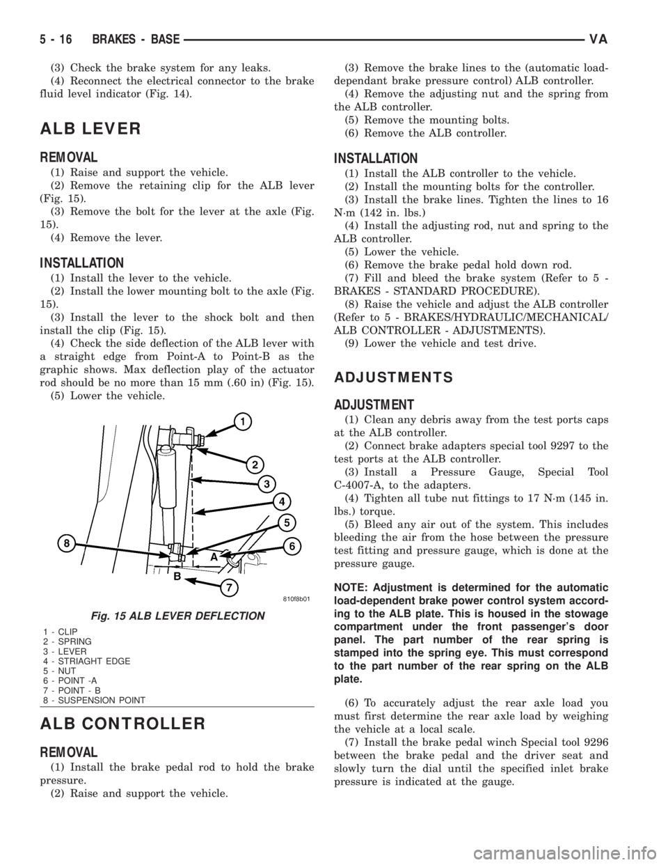
(4) Check the side deflection of the ALB lever with
a straight edge from Point-A to Point-B as the
graphic shows. Max deflection play of the actuator
rod should be no more than 15 mm (.60 in) (Fig. 15).
(5) Lower the vehicle.
ALB CONTROLLER
REMOVAL
(1) Install the brake pedal rod to hold the brake
pressure.
(2) Raise and support the vehicle.(3) Remove the brake lines to the (automatic load-
dependant brake pressure control) ALB controller.
(4) Remove the adjusting nut and the spring from
the ALB controller.
(5) Remove the mounting bolts.
(6) Remove the ALB controller.
INSTALLATION
(1) Install the ALB controller to the vehicle.
(2) Install the mounting bolts for the controller.
(3) Install the brake lines. Tighten the lines to 16
N´m (142 in. lbs.)
(4) Install the adjusting rod, nut and spring to the
ALB controller.
(5) Lower the vehicle.
(6) Remove the brake pedal hold down rod.
(7) Fill and bleed the brake system (Refer to 5 -
BRAKES - STANDARD PROCEDURE).
(8) Raise the vehicle and adjust the ALB controller
(Refer to 5 - BRAKES/HYDRAULIC/MECHANICAL/
ALB CONTROLLER - ADJUSTMENTS).
(9) Lower the vehicle and test drive.
ADJUSTMENTS
ADJUSTMENT
(1) Clean any debris away from the test ports caps
at the ALB controller.
(2) Connect brake adapters special tool 9297 to the
test ports at the ALB controller.
(3) Install a Pressure Gauge, Special Tool
C-4007-A, to the adapters.
(4) Tighten all tube nut fittings to 17 N´m (145 in.
lbs.) torque.
(5) Bleed any air out of the system. This includes
bleeding the air from the hose between the pressure
test fitting and pressure gauge, which is done at the
pressure gauge.
NOTE: Adjustment is determined for the automatic
load-dependent brake power control system accord-
ing to the ALB plate. This is housed in the stowage
compartment under the front passenger's door
panel. The part number of the rear spring is
stamped into the spring eye. This must correspond
to the part number of the rear spring on the ALB
plate.
(6) To accurately adjust the rear axle load you
must first determine the rear axle load by weighing
the vehicle at a local scale.
(7) Install the brake pedal winch Special tool 9296
between the brake pedal and the driver seat and
slowly turn the dial until the specified inlet brake
pressure is indicated at the gauge.
Fig. 15 ALB LEVER DEFLECTION
1 - CLIP
2 - SPRING
3 - LEVER
4 - STRIAGHT EDGE
5 - NUT
6 - POINT -A
7 - POINT - B
8 - SUSPENSION POINT
5 - 16 BRAKES - BASEVA
Page 953 of 2305
seat riser, a fog lamp switch installed in the cluster
bezel on the instrument panel outboard of the steer-
ing column, and a fog lamp bulb installed in each of
the two front lamp units. The front fog lamps have a
path to ground at all times through their connection
to the vehicle wire harness. The headlamp switch cir-
cuitry of the left (lighting) control stalk of the multi-
function switch controls front fog lamp operation by
providing battery current to the front fog lamp relay
only when the low beam headlamps are selected. The
fog lamp switch controls front fog lamp operation by
energizing or de-energizing the front fog lamp relay
control coil.
HAZARD WARNING LAMPS
With the hazard switch in the On position, the
hazard switch button illuminates and the right and
left turn signal indicators as well as the right and
left turn signal lamps begin to flash on and off. When
the hazard warning system is activated, the hazard
switch circuitry within the multi-function switch and
the wipers, turn signals and engine start control
module electronic circuitry within the fuse block will
repeatedly energize and de-energize the turn signal
relay located in the fuse block. The turn signal relay
switches battery current from a fused B(+) fuse in
the fuse block to the turn signal indicators and the
turn signal lamps. The flashing of the hazard switch
button illumination lamp is also controlled by the
output from the turn signal relay.
HEADLAMPS
The headlamp system includes the exterior lighting
switches integral to the left (lighting) control stalk of
the multi-function switch as well as the low and high
beam bulbs installed in the right and left front lamp
units (Fig. 1). The headlamp bulbs have a path to
ground at all times through the vehicle wire harness.
The exterior lighting switches control headlamp oper-
ation by providing battery current to the selected low
or high beam bulbs. Each front lamp unit includes
two integral adjustment screws to be used for static
horizontal and vertical aiming of the headlamp beam
reflectors.HEADLAMP LEVELING
The headlamp leveling system includes a leveling
actuator motor integral to each front lamp unit, and
a rotary thumbwheel actuated headlamp leveling
switch in the cluster bezel on the instrument panel
outboard of the steering column. The headlamp lev-
eling system allows the headlamp beam reflectors to
be adjusted to one of four vertical positions to com-
pensate for changes in inclination caused by the load-
ing of the vehicle suspension. The actuator motors
are mechanically connected through an integral
pushrod to an adjustable headlamp reflector. The
headlamp leveling switch is a resistor multiplexed
unit that provides one of four voltage outputs to the
headlamp leveling motors. The headlamp leveling
motors will move the headlamps to the selected posi-
tion based upon the voltage input received from the
switch. The headlamp leveling motors and switch
have a path to ground at all times. The headlamp
leveling components operate on battery current
received through the park lamps circuit so that the
system will only operate when the exterior lighting is
turned on.
PARK LAMPS
The park lamps system includes the exterior light-
ing switches integral to the left (lighting) control
stalk of the multi-function switch (Fig. 1), the front
park/side marker lamps, the front position lamps, the
rear park lamps, the rear side marker lamps, the
optional clearance lamps, and the license plate
lamps. Each of these lamps are provided with a path
to ground at all times through the vehicle wire har-
ness. The exterior lighting switches control the park
lamp operation by providing battery current through
the park lamps circuit to the appropriate lamp bulbs.
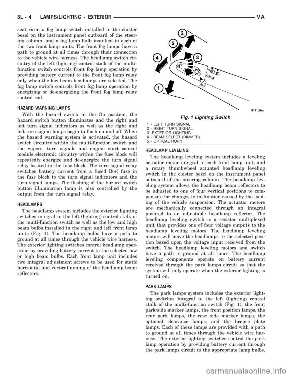
Fig. 1 Lighting Switch
1 - LEFT TURN SIGNAL
2 - RIGHT TURN SIGNAL
3 -EXTERIOR LIGHTING
4 - BEAM SELECT (DIMMER)
5 - OPTICAL HORN
8L - 4 LAMPS/LIGHTING - EXTERIORVA
Page 1589 of 2305
DESCRIPTION N´m Ft. Lbs. In. Lbs.
Oil Filter
Screw Cap to Oil Filter 25 18.5 -
Oil Cooling System
Bolt-Oil-Water Heat Ex-
changer to Timing Cover
Case15 - 133
Oil Level Pressure
Bolt-Dip Stick Guide Tube
to Cylinder Head14 - 123
Bolt-Oil Level Sensor to
Oil Pan14 - 123
Coolant Pre-Heater
Coolant Pre-Heater in En-
gine Block35 26 -
Engine Cooling General
Bolt-Belt Pulley to Coolant
Pump8-35 6 - 26 -
Bolt-Coolant Pump to
Timing Case Cover 6m/
8m14/20 10 - 15 -
Bolt-Thremostat Housing
to Cylinder Head9-80
Coolant Drain Plug to
Crankcase30 22 -
Engine Suspension, Engine Mount, Engine Bracket
Bolt-Engine Bracket to
Crankcase (2 stage,
torque, torque angle)20/90É 15, 90É -
Bolt-Engine Mount to En-
gine Bracket55 40.5 -
Bolt-Front Engine Mount
to Front Axle Carrier35 26 -
Bolt-Rear Engine Cross
Member to Body40 30 -
Bolt-Rear Engine Mount
to Rear Engine Cross
Member35 26 -
Bolt/Nut- Rear Engine
Mount to Transmission40 26 -
Bolt-Shrowd to Engine
Bracket10 - 88.5
Nut-Front Engine Mount
to Engine Bracket65 48 -
Nut-Engine Mount to Ve-
hicle Frame35 26 -
Fuel Filter
Bolt-Clip to Fuel Filter 8 - 70
9 - 14 ENGINEVA
Page 1677 of 2305
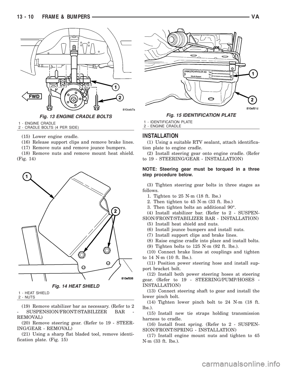
(15) Lower engine cradle.
(16) Release support clips and remove brake lines.
(17) Remove nuts and remove jounce bumpers.
(18) Remove nuts and remove mount heat shield.
(Fig. 14)
(19) Remove stabilizer bar as necessary. (Refer to 2
- SUSPENSION/FRONT/STABILIZER BAR -
REMOVAL)
(20) Remove steering gear. (Refer to 19 - STEER-
ING/GEAR - REMOVAL)
(21) Using a sharp flat bladed tool, remove identi-
fication plate. (Fig. 15)INSTALLATION
(1) Using a suitable RTV sealant, attach identifica-
tion plate to engine cradle.
(2) Install steering gear onto engine cradle. (Refer
to 19 - STEERING/GEAR - INSTALLATION)
NOTE: Steering gear must be torqued in a three
step procedure below.
(3) Tighten steering gear bolts in three stages as
follows.
1. Tighten to 25 N´m (18 ft. lbs.)
2. Then tighten to 45 N´m (33 ft. lbs.)
3. Then tighten bolts an additional 90É.
(4) Install stabilizer bar. (Refer to 2 - SUSPEN-
SION/FRONT/STABILIZER BAR - INSTALLATION)
(5) Install heat shield and nuts.
(6) Install jounce bumpers and install nuts.
(7) Install support clips and brake lines.
(8) Raise engine cradle into place and install bolts.
(9) Tighten bolts to 125 N´m (92 ft. lbs.).
(10) Connect brake lines at couplings and tighten
to 14 N´m (10 ft. lbs.).
(11) Position power steering hose and install sup-
port bracket bolt.
(12) Install both power steering hoses at steering
gear. (Refer to 19 - STEERING/PUMP/HOSES -
INSTALLATION)
(13) Connect steering shaft to gear and install the
lower pinch bolt.
(14) Tighten lower pinch bolt to 24 N´m (18 ft.
lbs.).
(15) Install new tie straps holding transmission
harness to cradle.
(16) Install front spring. (Refer to 2 - SUSPEN-
SION/FRONT/SPRING - INSTALLATION)
(17) Install engine mount nuts and tighten to 45
N´m (33 ft. lbs.).
Fig. 13 ENGINE CRADLE BOLTS
1 - ENGINE CRADLE
2 - CRADLE BOLTS (4 PER SIDE)
Fig. 14 HEAT SHIELD
1 - HEAT SHIELD
2 - NUTS
Fig. 15 IDENTIFICATION PLATE
1 - IDENTIFICATION PLATE
2 - ENGINE CRADLE
13 - 10 FRAME & BUMPERSVA
Page 1678 of 2305
(18) Install calipers. (Refer to 5 - BRAKES/HY-
DRAULIC/MECHANICAL/DISC BRAKE CALIPERS
- INSTALLATION)
(19) Install new tie straps holding wheel speed
sensors and brake pad wear sensors wire harness to
cradle.
(20) Check and align vehicle to specifications.
(Refer to 2 - SUSPENSION/WHEEL ALIGNMENT -
STANDARD PROCEDURE)
REAR CROSSMEMBER -
TRANSMISSION
REMOVAL
(1) Raise and support the vehicle. (Refer to
LUBRICATION & MAINTENANCE/HOISTING -
STANDARD PROCEDURE)
(2) Support transmission with a suitable lifting
device.
(3) Remove the bolts/nuts and remove transmis-
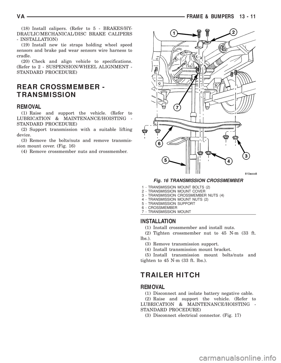
sion mount cover. (Fig. 16)
(4) Remove crossmember nuts and crossmember.
INSTALLATION
(1) Install crossmember and install nuts.
(2) Tighten crossmember nut to 45 N´m (33 ft.
lbs.).
(3) Remove transmission support.
(4) Install transmission mount bracket.
(5) Install transmission mount bolts/nuts and
tighten to 45 N´m (33 ft. lbs.).
TRAILER HITCH
REMOVAL
(1) Disconnect and isolate battery negative cable.
(2) Raise and support the vehicle. (Refer to
LUBRICATION & MAINTENANCE/HOISTING -
STANDARD PROCEDURE)
(3) Disconnect electrical connector. (Fig. 17)
Fig. 16 TRANSMISSION CROSSMEMBER
1 - TRANSMISSION MOUNT BOLTS (2)
2 - TRANSMISSION MOUNT COVER
3 - TRANSMISSION CROSSMEMBER NUTS (4)
4 - TRANSMISSION MOUNT NUTS (2)
5 - TRANSMISSION SUPPORT
6 - CROSSMEMBER
7 - TRANSMISSION MOUNT
VAFRAME & BUMPERS 13 - 11
Page 1731 of 2305
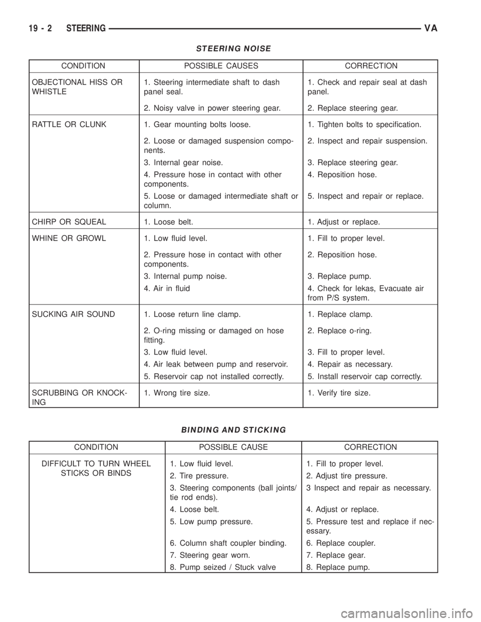
STEERING NOISE
CONDITION POSSIBLE CAUSES CORRECTION
OBJECTIONAL HISS OR
WHISTLE1. Steering intermediate shaft to dash
panel seal.1. Check and repair seal at dash
panel.
2. Noisy valve in power steering gear. 2. Replace steering gear.
RATTLE OR CLUNK 1. Gear mounting bolts loose. 1. Tighten bolts to specification.
2. Loose or damaged suspension compo-
nents.2. Inspect and repair suspension.
3. Internal gear noise. 3. Replace steering gear.
4. Pressure hose in contact with other
components.4. Reposition hose.
5. Loose or damaged intermediate shaft or
column.5. Inspect and repair or replace.
CHIRP OR SQUEAL 1. Loose belt. 1. Adjust or replace.
WHINE OR GROWL 1. Low fluid level. 1. Fill to proper level.
2. Pressure hose in contact with other
components.2. Reposition hose.
3. Internal pump noise. 3. Replace pump.
4. Air in fluid 4. Check for lekas, Evacuate air
from P/S system.
SUCKING AIR SOUND 1. Loose return line clamp. 1. Replace clamp.
2. O-ring missing or damaged on hose
fitting.2. Replace o-ring.
3. Low fluid level. 3. Fill to proper level.
4. Air leak between pump and reservoir. 4. Repair as necessary.
5. Reservoir cap not installed correctly. 5. Install reservoir cap correctly.
SCRUBBING OR KNOCK-
ING1. Wrong tire size. 1. Verify tire size.
BINDING AND STICKING
CONDITION POSSIBLE CAUSE CORRECTION
DIFFICULT TO TURN WHEEL
STICKS OR BINDS1. Low fluid level. 1. Fill to proper level.
2. Tire pressure. 2. Adjust tire pressure.
3. Steering components (ball joints/
tie rod ends).3 Inspect and repair as necessary.
4. Loose belt. 4. Adjust or replace.
5. Low pump pressure. 5. Pressure test and replace if nec-
essary.
6. Column shaft coupler binding. 6. Replace coupler.
7. Steering gear worn. 7. Replace gear.
8. Pump seized / Stuck valve 8. Replace pump.
19 - 2 STEERINGVA
Page 1732 of 2305
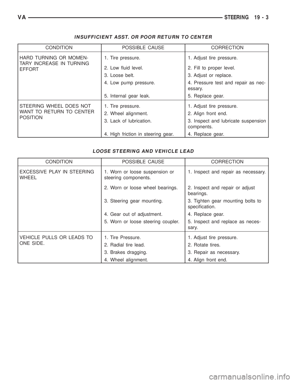
INSUFFICIENT ASST. OR POOR RETURN TO CENTER
CONDITION POSSIBLE CAUSE CORRECTION
HARD TURNING OR MOMEN-
TARY INCREASE IN TURNING
EFFORT1. Tire pressure. 1. Adjust tire pressure.
2. Low fluid level. 2. Fill to proper level.
3. Loose belt. 3. Adjust or replace.
4. Low pump pressure. 4. Pressure test and repair as nec-
essary.
5. Internal gear leak. 5. Replace gear.
STEERING WHEEL DOES NOT
WANT TO RETURN TO CENTER
POSITION1. Tire pressure. 1. Adjust tire pressure.
2. Wheel alignment. 2. Align front end.
3. Lack of lubrication. 3. Inspect and lubricate suspension
compnents.
4. High friction in steering gear. 4. Replace gear.
LOOSE STEERING AND VEHICLE LEAD
CONDITION POSSIBLE CAUSE CORRECTION
EXCESSIVE PLAY IN STEERING
WHEEL1. Worn or loose suspension or
steering components.1. Inspect and repair as necessary.
2. Worn or loose wheel bearings. 2. Inspect and repair or adjust
bearings.
3. Steering gear mounting. 3. Tighten gear mounting bolts to
specification.
4. Gear out of adjustment. 4. Replace gear.
5. Worn or loose steering coupler. 5. Inspect and replace as neces-
sary.
VEHICLE PULLS OR LEADS TO
ONE SIDE.1. Tire Pressure. 1. Adjust tire pressure.
2. Radial tire lead. 2. Rotate tires.
3. Brakes dragging. 3. Repair as necessary.
4. Wheel alignment. 4. Align front end.
VASTEERING 19 - 3