2006 MERCEDES-BENZ SPRINTER width
[x] Cancel search: widthPage 1940 of 2305

WHEELS
DESCRIPTION
Original equipment wheels are designed for the
specified Maximum Vehicle Capacity.
All models use steel or aluminum wheels.
Aluminum wheels require special balance weights
and alignment equipment.
(1) On vehicles equipped with dual rear wheels,
The slots in the wheel must be aligned to provide
access to the valve stem.
OPERATION
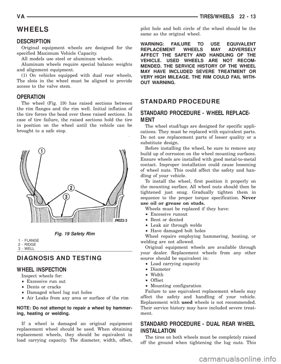
The wheel (Fig. 19) has raised sections between
the rim flanges and the rim well. Initial inflation of
the tire forces the bead over these raised sections. In
case of tire failure, the raised sections hold the tire
in position on the wheel until the vehicle can be
brought to a safe stop.
DIAGNOSIS AND TESTING
WHEEL INSPECTION
Inspect wheels for:
²Excessive run out
²Dents or cracks
²Damaged wheel lug nut holes
²Air Leaks from any area or surface of the rim
NOTE: Do not attempt to repair a wheel by hammer-
ing, heating or welding.
If a wheel is damaged an original equipment
replacement wheel should be used. When obtaining
replacement wheels, they should be equivalent in
load carrying capacity. The diameter, width, offset,pilot hole and bolt circle of the wheel should be the
same as the original wheel.
WARNING: FAILURE TO USE EQUIVALENT
REPLACEMENT WHEELS MAY ADVERSELY
AFFECT THE SAFETY AND HANDLING OF THE
VEHICLE. USED WHEELS ARE NOT RECOM-
MENDED. THE SERVICE HISTORY OF THE WHEEL
MAY HAVE INCLUDED SEVERE TREATMENT OR
VERY HIGH MILEAGE. THE RIM COULD FAIL WITH-
OUT WARNING.
STANDARD PROCEDURE
STANDARD PROCEDURE - WHEEL REPLACE-
MENT
The wheel stud/lugs are designed for specific appli-
cations. They must be replaced with equivalent parts.
Do not use replacement parts of lesser quality or a
substitute design.
Before installing the wheel, be sure to remove any
build up of corrosion on the wheel mounting surfaces.
Ensure wheels are installed with good metal-to-metal
contact. Improper installation could cause loosening
of wheel nuts. This could affect the safety and han-
dling of your vehicle.
To install the wheel, first position it properly on
the mounting surface. All wheel nuts should then be
tightened just snug. Gradually tighten them in
sequence to the proper torque specification.Never
use oil or grease on studs.
Wheels must be replaced if they have:
²Excessive runout
²Bent or dented
²Leak air through welds
²Have damaged bolt holes
Wheel repairs employing hammering, heating, or
welding are not allowed.
Original equipment wheels are available through
your dealer. Replacement wheels from any other
source should be equivalent in:
²Load carrying capacity
²Diameter
²Width
²Offset
²Mounting configuration
Failure to use equivalent replacement wheels may
affect the safety and handling of your vehicle.
Replacement withusedwheels is not recommended.
Their service history may have included severe treat-
ment.
STANDARD PROCEDURE - DUAL REAR WHEEL
INSTALLATION
The tires on both wheels must be completely raised
off the ground when tightening the lug nuts. This
Fig. 19 Safety Rim
1 - FLANGE
2 - RIDGE
3 - WELL
VATIRES/WHEELS 22 - 13
Page 1951 of 2305

(5) If desired, a thin film coat of adhesive can be
applied to the back of the patch to cover mesh for
added strength.
PANEL PATCH INSTALLATION
(1) Make a paper or cardboard pattern the size
and shape of the cutout hole in the panel.
(2) Trim 3 mm (0.125 in.) from edges of pattern so
patch will have a gap between connecting surfaces.
(3) Using the pattern as a guide, cut the patch to
size.
(4) Cut scrap pieces of patch material into 50 mm
(2 in.) squares to use as patch supports to sustain
the patch in the cutout.
(5) Drill 4 mm (0.160 in.) holes 13 mm (0.5 in.) in
from edge of cutout hole (Fig. 7).
(6) Drill 4 mm (0.160 in.) holes 13 mm (0.5 in.)
away from edge of patch across from holes drilled
around cutout.
(7) Drill 3 mm (0.125 in.) holes in the support
squares 13 mm (0.5 in.) from the edge in the center
of one side.
(8) Scuff the backside of the body panel around the
cutout hole with a scuff pad or sandpaper.
(9) Mix enough adhesive to cover one side of all
support squares.
(10) Apply adhesive to cover one side of all support
squares.
(11) Using number 8 sheet metal screws, secure
support squares to back side of body panel with
adhesive sandwiched between the panel and squares
(Fig. 9).(12) Position patch in cutout against support
squares and adjust patch until the gap is equal along
all sides (Fig. 10).
(13) Drill 3 mm (0.125 in.) holes in the support
squares through the pre-drilled holes in the patch.
(14) Apply a coat of adhesive to the exposed ends
of the support squares (Fig. 11).
(15) Install screws to hold the patch to support
squares (Fig. 12). Tighten screws until patch surface
is flush with panel surface.
(16) Allow adhesive to cure, and remove all screws.
(17) Using a 125 mm (5 in.) 24 grit disc grinder,
grind a 50 mm (2 in.) to 75 mm (3 in.) wide and 2
mm (0.080 in.) deep path across the gaps around the
patch (Fig. 13). With compressed air, blow dust from
around patch.
(18) Apply adhesive backed nylon mesh (dry wall
tape) over gaps around patch (Fig. 14).
(19) Mix enough adhesive to cover the entire patch
area.
(20) Apply adhesive over the mesh around patch,
and smooth epoxy with a wide spreader to reduce fin-
ish grinding. Use two to three layers of mesh and
adhesive to create a stronger repair (Fig. 15).
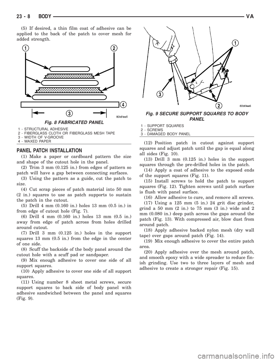
Fig. 8 FABRICATED PANEL
1 - STRUCTURAL ADHESIVE
2 - FIBERGLASS CLOTH OR FIBERGLASS MESH TAPE
3 - WIDTH OF V-GROOVE
4 - WAXED PAPER
Fig. 9 SECURE SUPPORT SQUARES TO BODY
PANEL
1 - SUPPORT SQUARES
2 - SCREWS
3 - DAMAGED BODY PANEL
23 - 8 BODYVA
Page 2168 of 2305

3-4 solenoid -The 3-4 solenoid is activated when
the TCM determines that the transmission must
shift into or out of 4th gear. The solenoid is only
activated during the shifting of the transmission.
When the solenoid is activated, hydraulic pressure
is applied to the proper shift elements in the trans-
mission to allow the desired shift. Once the shift is
completed, the solenoid is turned off.
TCC solenoid -The TCC solenoid is activated
when the TCM determines that the Torque con-
verter clutch should be activated. The TCC clutch is
a variable slip torque clutch that allows control of
torque converter slip from 5% to 95.5% of full TCC
engagement. The clutch is controlled by the TCC
solenoid which is pulse width modulated (PWM) to
provide the desired amount of slip.
Shift Pressure Solenoid -The Shift Pressure
Solenoid is activated when the TCM determines
that a transmission shift is required. The solenoid
is PWM controller to allow the proper amount of
hydraulic pressure to the shift elements. The sole-
noid is only activated during the shifting of the
transmission. When the solenoid is activated, hy-
draulic pressure is removed from the proper shift
elements to allow the desired shift. Once the shift is
completed, the solenoid is turned off.
Modulation pressure solenoid -The modulation
pressure is always active. The solenoid is pulse
width modulated (PWM) controlled and is used to
modulate the hydraulic system pressure to the
desired pressure.
3.2.4 TRANSMISSION COMPONENT
DESCRIPTIONS
Shift Assembly
The Shift Lever Selector transmits all selector lever
positions, as well as selected shift ranges to the
TCM over the CAN Bus. At the same time, the
selector lever positions P, R, N, and D are transmit-
ted by a cable to the selector lever shaft in the
transmission.
Brake shift inter-lock
To prevent unauthorized shifting out of the park
position, the Selector lever is locked in the Park
position until the ignition key is turned to the run
position and the brake pedal is pressed. This will
allow the driver to shift out of the park position.
Reverse Lamp Output
The Reverse Light Switch is integrated into the
shifter module and controls the reverse lights.
Reverse Inhibitor
The Shift Lever Assembly constantly monitors ABS
wheel speed to prevents an inadvertent selection of
reverse at speeds above approximately 6.4 Km/h(4MPH). The Reverse inhibitor is part of the Shift
Lever Assembly and is controlled by the Shift Lever
Assembly module.
Trans temp sensor - P/N Switch circuit
The TCM will detect the selector lever in park and
neutral positions. The TCM does this by monitoring
the Transmission temperature sensor signal along
with the shifter position signals. The P/N switch
contact is operated by a cam located in the trans-
mission which, opens a reed contact switch that is
wired in series with the transmission temperature
sensor. When the P/N contact switch is opened in
park and neutral, the TCM senses a high transmis-
sion temperature. Confirming the P/N switch sta-
tus. Note: In park or neutral, the TCM uses engine
temperature (to avoid setting a DTC). The TCM
sends a hardwired signal to the ECM that will allow
the ECM controlled start circuit to engage in P or N
only. The TCM also sends a P/N bus message to the
ECM to confirm the P/N switch status.
The Normal Transmission Temperature Sensor
resistance is between 500.0 and 2500.0 ohms.
The normal voltage limits for the transmis-
sion temperature sensor, are between 0.5 and
3.0 volts.
Input Speed Sensors
The NAG1 transmission has two input speed sen-
sors N2 and N3, both speed sensors are located on
the valve body and report DTC's for the input speed
sensors errors. The speed sensors are Hall Effect
speed sensors that are used by the TCM to calculate
the transmissions input speed. Since the input
speed could not be measured directly, two of the
drive elements are measured. Two input speed
sensors were required because both drive elements
are not active in all gears. The input sensors N2 and
N3 will report the same input speed in gears 2nd,
3rd or 4th. If the N2 and N3 input speed signals are
not the same in these gears then there is an issue
with the transmission and the DTC Input Sensors
Mismatch will be set.
The N3 input speed is not reported in1st and 5th
gears. The N2 sensor is not reported in Reverse.
The Input Speed Sensor Overspeed is a rationality
check that is intended to indicate a major transmis-
sion failure and will cause a loss of drive (place the
transmission in Neutral)
Output Speed Sensor (ABS signal)
The NAG1 transmission does not have an output
shaft speed sensor. The TCM uses the ABS (An-
tilock Brake System) Wheel Speed sensor informa-
tion, it receives over the CAN bus, to calculate the
transmissions output shaft speed. The TCM moni-
tors the ABS system for functionality and reports
ABS speed sensor and communication DTCs, which
will affect proper transmission operation.
3
GENERAL INFORMATION
Page 2173 of 2305

5.0 REQUIRED TOOLS AND
EQUIPMENT
> DRBIIIt(diagnostic read-out box) - DRBIIIt
must use the latest release level.
> Jumper wires
> Test Light
> Ohmmeter
> Voltmeter
6.0 GLOSSARY OF TERMS
6.1 ACRONYMS
ABSAntilock Braking system
A/CAir conditioner
A/DAnalog to Digital conversion
APPAccelerator Pedal Position
CANController Area Network (Vehicle
Bus System)
CKTCircuit
DLCData Link Connector
DRBIIItDiagnostic Readout Box
DTCDiagnostic Trouble Code
ECMDiesel Engine Controller
EMCCElectronically Modulated Converter
Clutch
IODIgnition off-draw
ISSInput Speed Sensor (N2 and N3)
KK line communication bus
LEDLight Emitting Diode
MILMalfunction Indicator LampOSSOutput Speed Sensor (derived from
the ABS controller)
PEMCCPartial Electronically Modulated
Converter Clutch
PWMPulse width modulated
SKREEMSentry Key Remote Entry Module
SLAShift Lever Assembly
SWSwitch
TCCTorque Converter Clutch
TCMTransmission Control Module
TPThrottle Position
TRDTorque Reduction
TTSTransmission Temperature Sensor
1-2/4-5
solenoidcontrols the shift into and out of
2nd gear or 5th gear.
V2-3 so-
lenoidcontrols the shift into and out of 3rd
gear
V3-4 so-
lenoidcontrols the shift into and out of 4th
gear
VTCC
solenoidis pulse width modulated and con-
trols the TCC clutch
Shift
Pressure
Solenoidis a pulse width modulated solenoid
and controls the hydraulic pressure
to the shift elements.
Modula-
tion
pressure
solenoidis a pulse width modulated solenoid
and controls the hydraulic system
pressure
6.2 DEFINITIONS
Driving cycle counter) -The starts since first set
counter indicates the number of driving cycles since
the first occurrence of an error.
8
GENERAL INFORMATION