2006 MERCEDES-BENZ SPRINTER brake light
[x] Cancel search: brake lightPage 332 of 2305
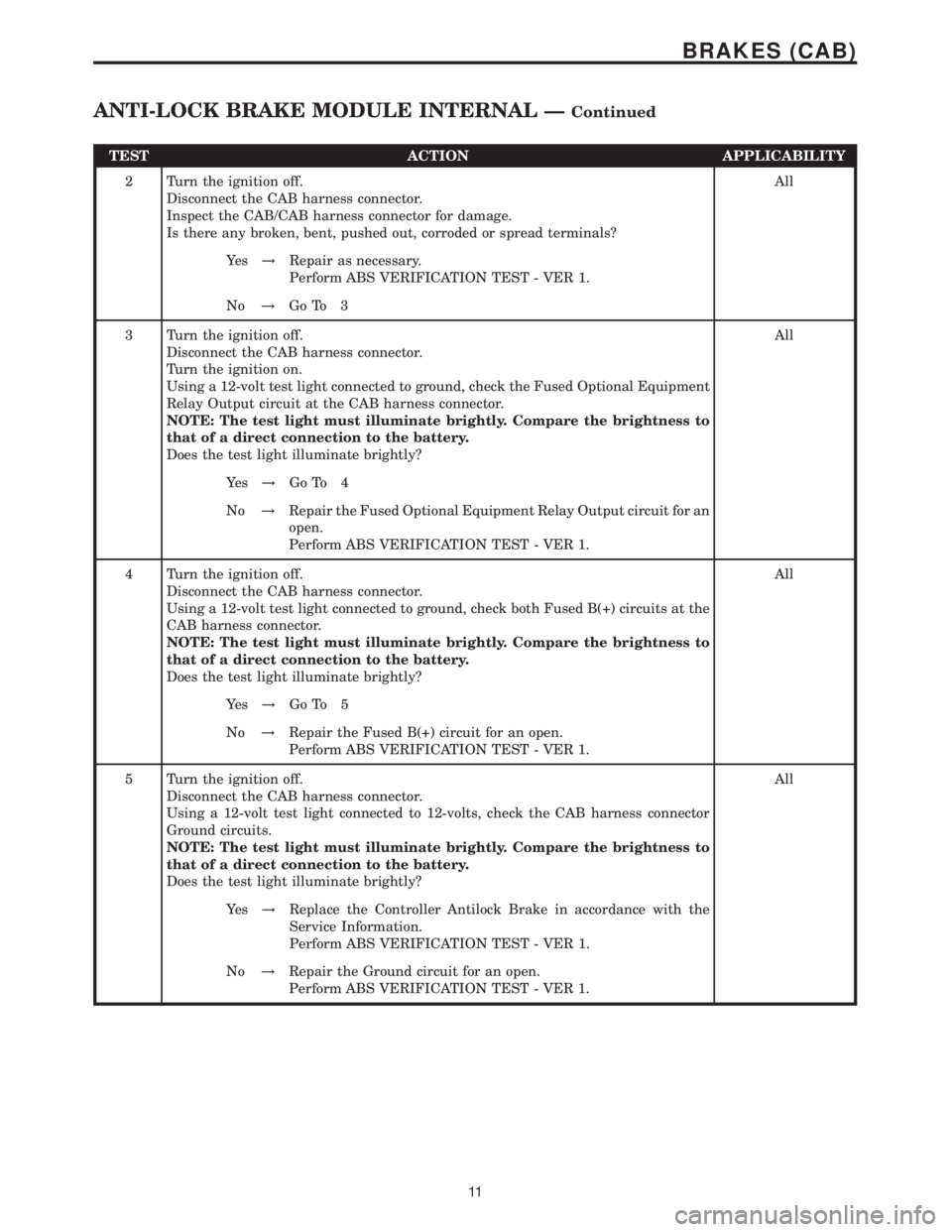
TEST ACTION APPLICABILITY
2 Turn the ignition off.
Disconnect the CAB harness connector.
Inspect the CAB/CAB harness connector for damage.
Is there any broken, bent, pushed out, corroded or spread terminals?All
Ye s!Repair as necessary.
Perform ABS VERIFICATION TEST - VER 1.
No!Go To 3
3 Turn the ignition off.
Disconnect the CAB harness connector.
Turn the ignition on.
Using a 12-volt test light connected to ground, check the Fused Optional Equipment
Relay Output circuit at the CAB harness connector.
NOTE: The test light must illuminate brightly. Compare the brightness to
that of a direct connection to the battery.
Does the test light illuminate brightly?All
Ye s!Go To 4
No!Repair the Fused Optional Equipment Relay Output circuit for an
open.
Perform ABS VERIFICATION TEST - VER 1.
4 Turn the ignition off.
Disconnect the CAB harness connector.
Using a 12-volt test light connected to ground, check both Fused B(+) circuits at the
CAB harness connector.
NOTE: The test light must illuminate brightly. Compare the brightness to
that of a direct connection to the battery.
Does the test light illuminate brightly?All
Ye s!Go To 5
No!Repair the Fused B(+) circuit for an open.
Perform ABS VERIFICATION TEST - VER 1.
5 Turn the ignition off.
Disconnect the CAB harness connector.
Using a 12-volt test light connected to 12-volts, check the CAB harness connector
Ground circuits.
NOTE: The test light must illuminate brightly. Compare the brightness to
that of a direct connection to the battery.
Does the test light illuminate brightly?All
Ye s!Replace the Controller Antilock Brake in accordance with the
Service Information.
Perform ABS VERIFICATION TEST - VER 1.
No!Repair the Ground circuit for an open.
Perform ABS VERIFICATION TEST - VER 1.
11
BRAKES (CAB)
ANTI-LOCK BRAKE MODULE INTERNAL ÐContinued
Page 340 of 2305
TEST ACTION APPLICABILITY
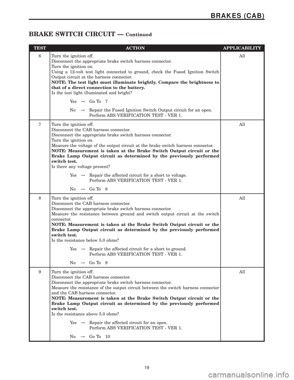
6 Turn the ignition off.
Disconnect the appropriate brake switch harness connector.
Turn the ignition on.
Using a 12-volt test light connected to ground, check the Fused Ignition Switch
Output circuit at the harness connector.
NOTE: The test light must illuminate brightly. Compare the brightness to
that of a direct connection to the battery.
Is the test light illuminated and bright?All
Ye s!Go To 7
No!Repair the Fused Ignition Switch Output circuit for an open.
Perform ABS VERIFICATION TEST - VER 1.
7 Turn the ignition off.
Disconnect the CAB harness connector.
Disconnect the appropriate brake switch harness connector.
Turn the ignition on.
Measure the voltage of the output circuit at the brake switch harness connector.
NOTE: Measurement is taken at the Brake Switch Output circuit or the
Brake Lamp Output circuit as determined by the previously performed
switch test.
Is there any voltage present?All
Ye s!Repair the affected circuit for a short to voltage.
Perform ABS VERIFICATION TEST - VER 1.
No!Go To 8
8 Turn the ignition off.
Disconnect the CAB harness connector.
Disconnect the appropriate brake switch harness connector.
Measure the resistance between ground and switch output circuit at the switch
connector.
NOTE: Measurement is taken at the Brake Switch Output circuit or the
Brake Lamp Output circuit as determined by the previously performed
switch test.
Is the resistance below 5.0 ohms?All
Ye s!Repair the affected circuit for a short to ground.
Perform ABS VERIFICATION TEST - VER 1.
No!Go To 9
9 Turn the ignition off.
Disconnect the CAB harness connector.
Disconnect the appropriate brake switch harness connector.
Measure the resistance of the output circuit between the switch harness connector
and the CAB harness connector.
NOTE: Measurement is taken at the Brake Switch Output circuit or the
Brake Lamp Output circuit as determined by the previously performed
switch test.
Is the resistance above 5.0 ohms?All
Ye s!Repair the affected circuit for an open.
Perform ABS VERIFICATION TEST - VER 1.
No!Go To 10
19
BRAKES (CAB)
BRAKE SWITCH CIRCUIT ÐContinued
Page 343 of 2305

TEST ACTION APPLICABILITY
3 Turn the ignition off.
Disconnect the CAB harness connector.
Turn the ignition on.
Using a 12-volt test light connected to ground, check the Fused Optional Equipment
Relay Output circuit at the CAB harness connector.
NOTE: The test light must illuminate brightly. Compare the brightness to
that of a direct connection to the battery.
Does the test light illuminate brightly?All
Ye s!Go To 4
No!Repair the Fused Optional Equipment Relay Output circuit for an
open.
Perform ABS VERIFICATION TEST - VER 1.
4 Turn the ignition off.
Disconnect the CAB harness connector.
Using a 12-volt test light connected to ground, check both Fused B(+) circuits at the
CAB harness connector.
NOTE: The test light must illuminate brightly. Compare the brightness to
that of a direct connection to the battery.
Does the test light illuminate brightly?All
Ye s!Go To 5
No!Repair the Fused B(+) circuit for an open.
Perform ABS VERIFICATION TEST - VER 1.
5 Turn the ignition off.
Disconnect the CAB harness connector.
Using a 12-volt test light connected to 12-volts, check the CAB harness connector
Ground circuits.
NOTE: The test light must illuminate brightly. Compare the brightness to
that of a direct connection to the battery.
Does the test light illuminate brightly?All
Ye s!Replace the Controller Antilock Brake in accordance with the
Service Information.
Perform ABS VERIFICATION TEST - VER 1.
No!Repair the Ground circuit for an open.
Perform ABS VERIFICATION TEST - VER 1.
6 Turn the ignition off.
Visually inspect the related wiring harness.
Look for any chafed, pierced, pinched, or partially broken wires.
Look for broken, bent, pushed out, or corroded terminals.
Were any problems found?All
Ye s!Repair as necessary.
Perform ABS VERIFICATION TEST - VER 1.
No!Test Complete.
22
BRAKES (CAB)
CAB CHECK SUM ÐContinued
Page 345 of 2305
TEST ACTION APPLICABILITY
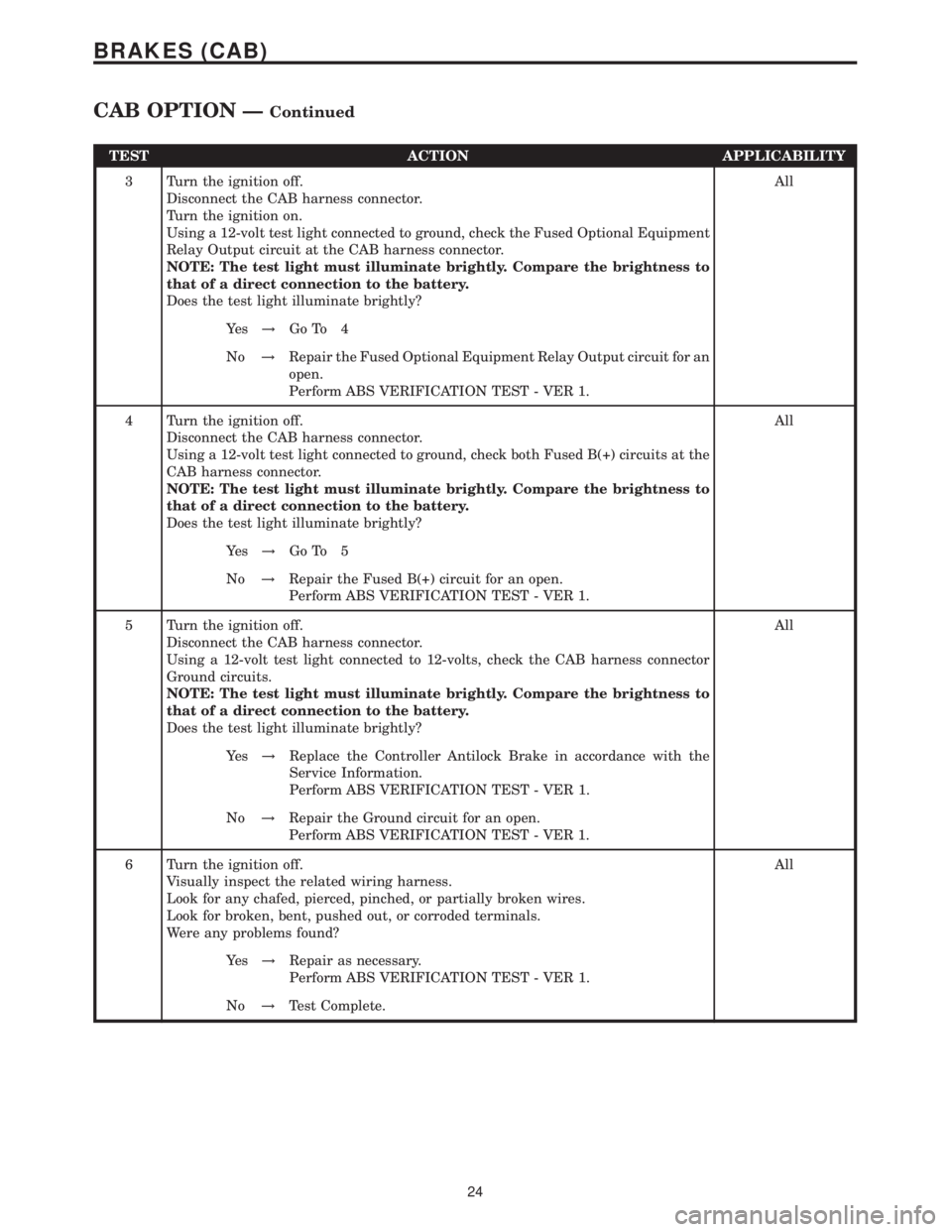
3 Turn the ignition off.
Disconnect the CAB harness connector.
Turn the ignition on.
Using a 12-volt test light connected to ground, check the Fused Optional Equipment
Relay Output circuit at the CAB harness connector.
NOTE: The test light must illuminate brightly. Compare the brightness to
that of a direct connection to the battery.
Does the test light illuminate brightly?All
Ye s!Go To 4
No!Repair the Fused Optional Equipment Relay Output circuit for an
open.
Perform ABS VERIFICATION TEST - VER 1.
4 Turn the ignition off.
Disconnect the CAB harness connector.
Using a 12-volt test light connected to ground, check both Fused B(+) circuits at the
CAB harness connector.
NOTE: The test light must illuminate brightly. Compare the brightness to
that of a direct connection to the battery.
Does the test light illuminate brightly?All
Ye s!Go To 5
No!Repair the Fused B(+) circuit for an open.
Perform ABS VERIFICATION TEST - VER 1.
5 Turn the ignition off.
Disconnect the CAB harness connector.
Using a 12-volt test light connected to 12-volts, check the CAB harness connector
Ground circuits.
NOTE: The test light must illuminate brightly. Compare the brightness to
that of a direct connection to the battery.
Does the test light illuminate brightly?All
Ye s!Replace the Controller Antilock Brake in accordance with the
Service Information.
Perform ABS VERIFICATION TEST - VER 1.
No!Repair the Ground circuit for an open.
Perform ABS VERIFICATION TEST - VER 1.
6 Turn the ignition off.
Visually inspect the related wiring harness.
Look for any chafed, pierced, pinched, or partially broken wires.
Look for broken, bent, pushed out, or corroded terminals.
Were any problems found?All
Ye s!Repair as necessary.
Perform ABS VERIFICATION TEST - VER 1.
No!Test Complete.
24
BRAKES (CAB)
CAB OPTION ÐContinued
Page 347 of 2305
TEST ACTION APPLICABILITY
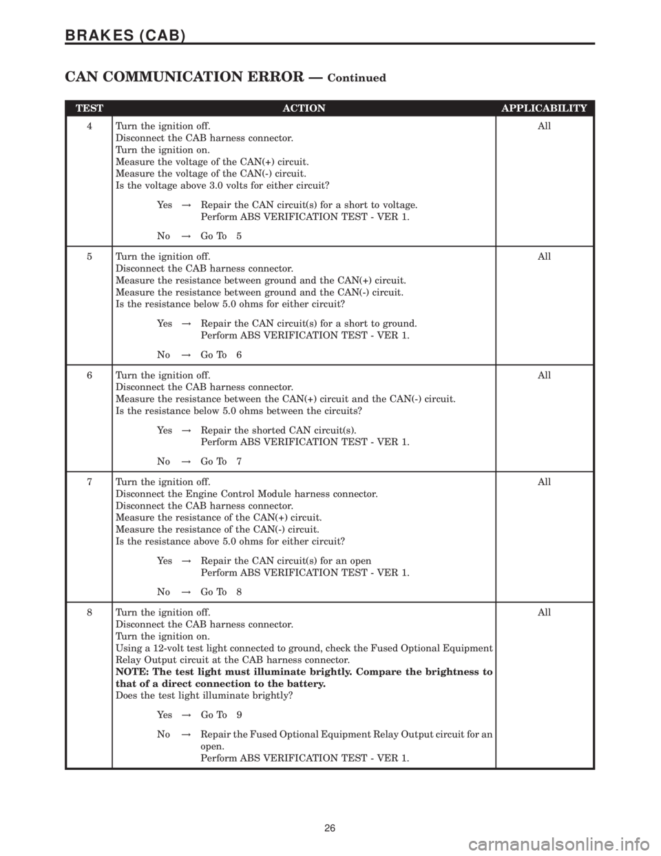
4 Turn the ignition off.
Disconnect the CAB harness connector.
Turn the ignition on.
Measure the voltage of the CAN(+) circuit.
Measure the voltage of the CAN(-) circuit.
Is the voltage above 3.0 volts for either circuit?All
Ye s!Repair the CAN circuit(s) for a short to voltage.
Perform ABS VERIFICATION TEST - VER 1.
No!Go To 5
5 Turn the ignition off.
Disconnect the CAB harness connector.
Measure the resistance between ground and the CAN(+) circuit.
Measure the resistance between ground and the CAN(-) circuit.
Is the resistance below 5.0 ohms for either circuit?All
Ye s!Repair the CAN circuit(s) for a short to ground.
Perform ABS VERIFICATION TEST - VER 1.
No!Go To 6
6 Turn the ignition off.
Disconnect the CAB harness connector.
Measure the resistance between the CAN(+) circuit and the CAN(-) circuit.
Is the resistance below 5.0 ohms between the circuits?All
Ye s!Repair the shorted CAN circuit(s).
Perform ABS VERIFICATION TEST - VER 1.
No!Go To 7
7 Turn the ignition off.
Disconnect the Engine Control Module harness connector.
Disconnect the CAB harness connector.
Measure the resistance of the CAN(+) circuit.
Measure the resistance of the CAN(-) circuit.
Is the resistance above 5.0 ohms for either circuit?All
Ye s!Repair the CAN circuit(s) for an open
Perform ABS VERIFICATION TEST - VER 1.
No!Go To 8
8 Turn the ignition off.
Disconnect the CAB harness connector.
Turn the ignition on.
Using a 12-volt test light connected to ground, check the Fused Optional Equipment
Relay Output circuit at the CAB harness connector.
NOTE: The test light must illuminate brightly. Compare the brightness to
that of a direct connection to the battery.
Does the test light illuminate brightly?All
Ye s!Go To 9
No!Repair the Fused Optional Equipment Relay Output circuit for an
open.
Perform ABS VERIFICATION TEST - VER 1.
26
BRAKES (CAB)
CAN COMMUNICATION ERROR ÐContinued
Page 348 of 2305
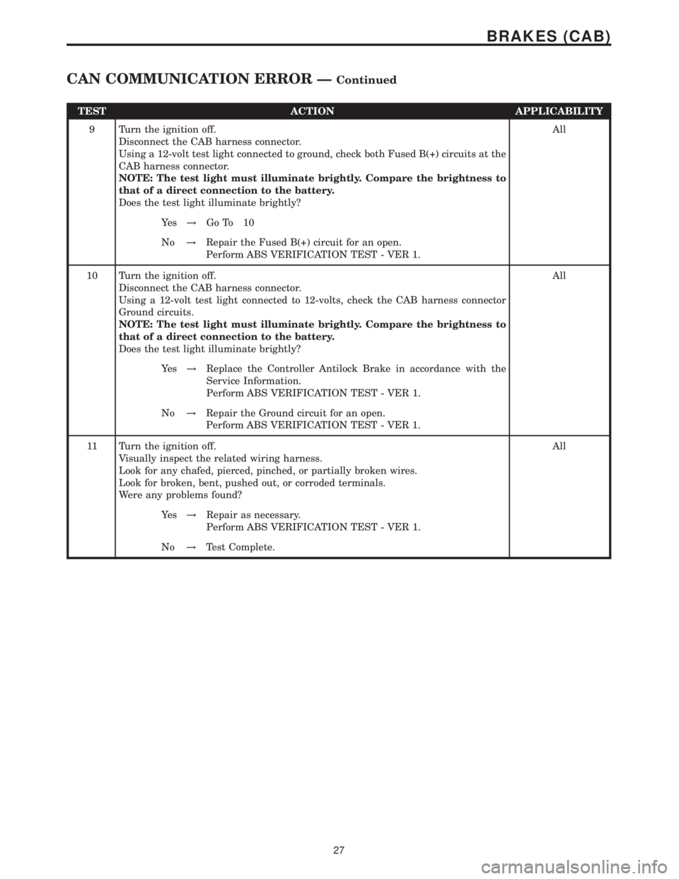
TEST ACTION APPLICABILITY
9 Turn the ignition off.
Disconnect the CAB harness connector.
Using a 12-volt test light connected to ground, check both Fused B(+) circuits at the
CAB harness connector.
NOTE: The test light must illuminate brightly. Compare the brightness to
that of a direct connection to the battery.
Does the test light illuminate brightly?All
Ye s!Go To 10
No!Repair the Fused B(+) circuit for an open.
Perform ABS VERIFICATION TEST - VER 1.
10 Turn the ignition off.
Disconnect the CAB harness connector.
Using a 12-volt test light connected to 12-volts, check the CAB harness connector
Ground circuits.
NOTE: The test light must illuminate brightly. Compare the brightness to
that of a direct connection to the battery.
Does the test light illuminate brightly?All
Ye s!Replace the Controller Antilock Brake in accordance with the
Service Information.
Perform ABS VERIFICATION TEST - VER 1.
No!Repair the Ground circuit for an open.
Perform ABS VERIFICATION TEST - VER 1.
11 Turn the ignition off.
Visually inspect the related wiring harness.
Look for any chafed, pierced, pinched, or partially broken wires.
Look for broken, bent, pushed out, or corroded terminals.
Were any problems found?All
Ye s!Repair as necessary.
Perform ABS VERIFICATION TEST - VER 1.
No!Test Complete.
27
BRAKES (CAB)
CAN COMMUNICATION ERROR ÐContinued
Page 362 of 2305
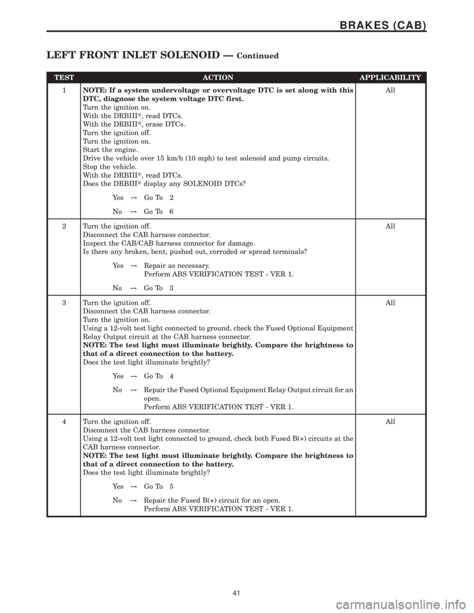
TEST ACTION APPLICABILITY
1NOTE: If a system undervoltage or overvoltage DTC is set along with this
DTC, diagnose the system voltage DTC first.
Turn the ignition on.
With the DRBIIIt, read DTCs.
With the DRBIIIt, erase DTCs.
Turn the ignition off.
Turn the ignition on.
Start the engine.
Drive the vehicle over 15 km/h (10 mph) to test solenoid and pump circuits.
Stop the vehicle.
With the DRBIIIt, read DTCs.
Does the DRBIIItdisplay any SOLENOID DTCs?All
Ye s!Go To 2
No!Go To 6
2 Turn the ignition off.
Disconnect the CAB harness connector.
Inspect the CAB/CAB harness connector for damage.
Is there any broken, bent, pushed out, corroded or spread terminals?All
Ye s!Repair as necessary.
Perform ABS VERIFICATION TEST - VER 1.
No!Go To 3
3 Turn the ignition off.
Disconnect the CAB harness connector.
Turn the ignition on.
Using a 12-volt test light connected to ground, check the Fused Optional Equipment
Relay Output circuit at the CAB harness connector.
NOTE: The test light must illuminate brightly. Compare the brightness to
that of a direct connection to the battery.
Does the test light illuminate brightly?All
Ye s!Go To 4
No!Repair the Fused Optional Equipment Relay Output circuit for an
open.
Perform ABS VERIFICATION TEST - VER 1.
4 Turn the ignition off.
Disconnect the CAB harness connector.
Using a 12-volt test light connected to ground, check both Fused B(+) circuits at the
CAB harness connector.
NOTE: The test light must illuminate brightly. Compare the brightness to
that of a direct connection to the battery.
Does the test light illuminate brightly?All
Ye s!Go To 5
No!Repair the Fused B(+) circuit for an open.
Perform ABS VERIFICATION TEST - VER 1.
41
BRAKES (CAB)
LEFT FRONT INLET SOLENOID ÐContinued
Page 363 of 2305

TEST ACTION APPLICABILITY
5 Turn the ignition off.
Disconnect the CAB harness connector.
Using a 12-volt test light connected to 12-volts, check the CAB harness connector
Ground circuits.
NOTE: The test light must illuminate brightly. Compare the brightness to
that of a direct connection to the battery.
Does the test light illuminate brightly?All
Ye s!Replace the Controller Antilock Brake in accordance with the
Service Information.
Perform ABS VERIFICATION TEST - VER 1.
No!Repair the Ground circuit for an open.
Perform ABS VERIFICATION TEST - VER 1.
6 Turn the ignition off.
Visually inspect the related wiring harness.
Look for any chafed, pierced, pinched, or partially broken wires.
Look for broken, bent, pushed out, or corroded terminals.
Were any problems found?All
Ye s!Repair as necessary.
Perform ABS VERIFICATION TEST - VER 1.
No!Test Complete.
42
BRAKES (CAB)
LEFT FRONT INLET SOLENOID ÐContinued