2006 MERCEDES-BENZ SPRINTER automatic transmission
[x] Cancel search: automatic transmissionPage 1845 of 2305
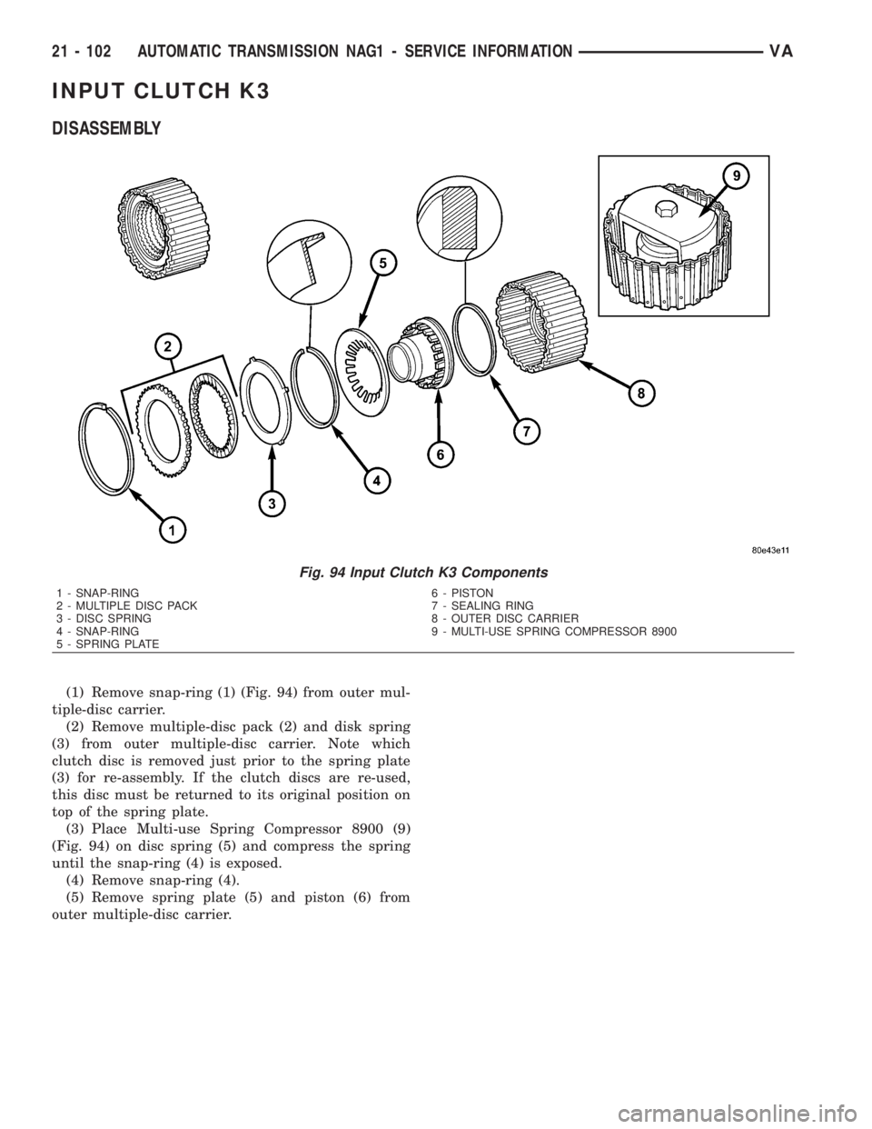
INPUT CLUTCH K3
DISASSEMBLY
(1) Remove snap-ring (1) (Fig. 94) from outer mul-
tiple-disc carrier.
(2) Remove multiple-disc pack (2) and disk spring
(3) from outer multiple-disc carrier. Note which
clutch disc is removed just prior to the spring plate
(3) for re-assembly. If the clutch discs are re-used,
this disc must be returned to its original position on
top of the spring plate.
(3) Place Multi-use Spring Compressor 8900 (9)
(Fig. 94) on disc spring (5) and compress the spring
until the snap-ring (4) is exposed.
(4) Remove snap-ring (4).
(5) Remove spring plate (5) and piston (6) from
outer multiple-disc carrier.
Fig. 94 Input Clutch K3 Components
1 - SNAP-RING 6 - PISTON
2 - MULTIPLE DISC PACK 7 - SEALING RING
3 - DISC SPRING 8 - OUTER DISC CARRIER
4 - SNAP-RING 9 - MULTI-USE SPRING COMPRESSOR 8900
5 - SPRING PLATE
21 - 102 AUTOMATIC TRANSMISSION NAG1 - SERVICE INFORMATIONVA
Page 1846 of 2305
ASSEMBLY
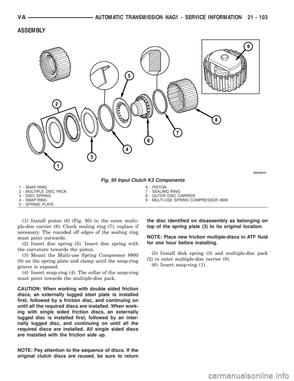
(1) Install piston (6) (Fig. 95) in the outer multi-
ple-disc carrier (8). Check sealing ring (7), replace if
necessary. The rounded off edges of the sealing ring
must point outwards.
(2) Insert disc spring (5). Insert disc spring with
the curvature towards the piston.
(3) Mount the Multi-use Spring Compressor 8900
(9) on the spring plate and clamp until the snap-ring
groove is exposed.
(4) Insert snap-ring (4). The collar of the snap-ring
must point towards the multiple-disc pack.
CAUTION: When working with double sided friction
discs, an externally lugged steel plate is installed
first, followed by a friction disc, and continuing on
until all the required discs are installed. When work-
ing with single sided friction discs, an externally
lugged disc is installed first, followed by an inter-
nally lugged disc, and continuing on until all the
required discs are installed. All single sided discs
are installed with the friction side up.
NOTE: Pay attention to the sequence of discs. If the
original clutch discs are reused, be sure to returnthe disc identified on disassembly as belonging on
top of the spring plate (3) to its original location.
NOTE: Place new friction multiple-discs in ATF fluid
for one hour before installing.
(5) Install disk spring (3) and multiple-disc pack
(2) in outer multiple-disc carrier (8).
(6) Insert snap-ring (1).
Fig. 95 Input Clutch K3 Components
1 - SNAP-RING 6 - PISTON
2 - MULTIPLE DISC PACK 7 - SEALING RING
3 - DISC SPRING 8 - OUTER DISC CARRIER
4 - SNAP-RING 9 - MULTI-USE SPRING COMPRESSOR 8900
5 - SPRING PLATE
VAAUTOMATIC TRANSMISSION NAG1 - SERVICE INFORMATION 21 - 103
Page 1847 of 2305
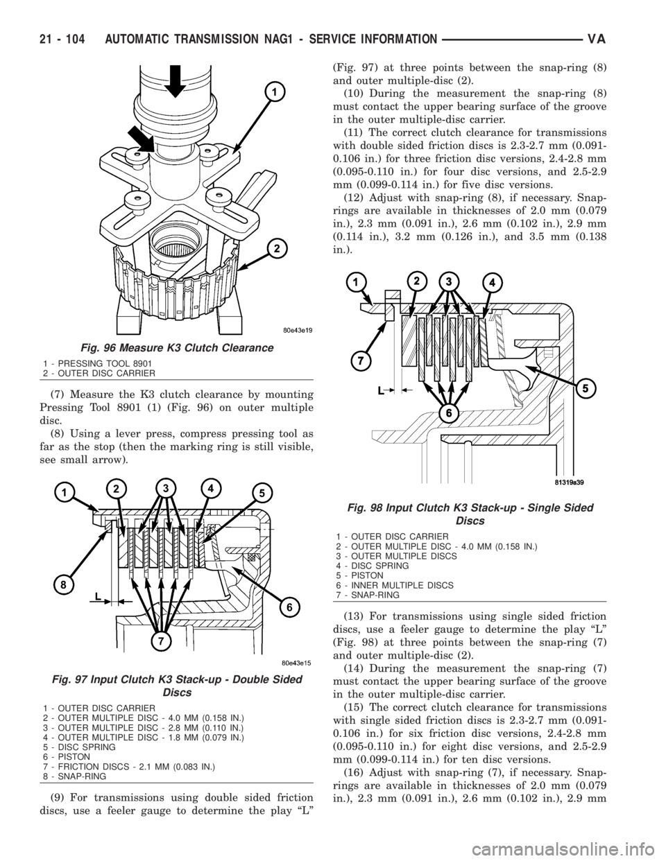
(7) Measure the K3 clutch clearance by mounting
Pressing Tool 8901 (1) (Fig. 96) on outer multiple
disc.
(8) Using a lever press, compress pressing tool as
far as the stop (then the marking ring is still visible,
see small arrow).
(9) For transmissions using double sided friction
discs, use a feeler gauge to determine the play ªLº(Fig. 97) at three points between the snap-ring (8)
and outer multiple-disc (2).
(10) During the measurement the snap-ring (8)
must contact the upper bearing surface of the groove
in the outer multiple-disc carrier.
(11) The correct clutch clearance for transmissions
with double sided friction discs is 2.3-2.7 mm (0.091-
0.106 in.) for three friction disc versions, 2.4-2.8 mm
(0.095-0.110 in.) for four disc versions, and 2.5-2.9
mm (0.099-0.114 in.) for five disc versions.
(12) Adjust with snap-ring (8), if necessary. Snap-
rings are available in thicknesses of 2.0 mm (0.079
in.), 2.3 mm (0.091 in.), 2.6 mm (0.102 in.), 2.9 mm
(0.114 in.), 3.2 mm (0.126 in.), and 3.5 mm (0.138
in.).
(13) For transmissions using single sided friction
discs, use a feeler gauge to determine the play ªLº
(Fig. 98) at three points between the snap-ring (7)
and outer multiple-disc (2).
(14) During the measurement the snap-ring (7)
must contact the upper bearing surface of the groove
in the outer multiple-disc carrier.
(15) The correct clutch clearance for transmissions
with single sided friction discs is 2.3-2.7 mm (0.091-
0.106 in.) for six friction disc versions, 2.4-2.8 mm
(0.095-0.110 in.) for eight disc versions, and 2.5-2.9
mm (0.099-0.114 in.) for ten disc versions.
(16) Adjust with snap-ring (7), if necessary. Snap-
rings are available in thicknesses of 2.0 mm (0.079
in.), 2.3 mm (0.091 in.), 2.6 mm (0.102 in.), 2.9 mm
Fig. 96 Measure K3 Clutch Clearance
1 - PRESSING TOOL 8901
2 - OUTER DISC CARRIER
Fig. 97 Input Clutch K3 Stack-up - Double Sided
Discs
1 - OUTER DISC CARRIER
2 - OUTER MULTIPLE DISC - 4.0 MM (0.158 IN.)
3 - OUTER MULTIPLE DISC - 2.8 MM (0.110 IN.)
4 - OUTER MULTIPLE DISC - 1.8 MM (0.079 IN.)
5 - DISC SPRING
6 - PISTON
7 - FRICTION DISCS - 2.1 MM (0.083 IN.)
8 - SNAP-RING
Fig. 98 Input Clutch K3 Stack-up - Single Sided
Discs
1 - OUTER DISC CARRIER
2 - OUTER MULTIPLE DISC - 4.0 MM (0.158 IN.)
3 - OUTER MULTIPLE DISCS
4 - DISC SPRING
5 - PISTON
6 - INNER MULTIPLE DISCS
7 - SNAP-RING
21 - 104 AUTOMATIC TRANSMISSION NAG1 - SERVICE INFORMATIONVA
Page 1848 of 2305
(0.114 in.), 3.2 mm (0.126 in.), and 3.5 mm (0.138
in.).
ELECTROHYDRAULIC UNIT
DESCRIPTION
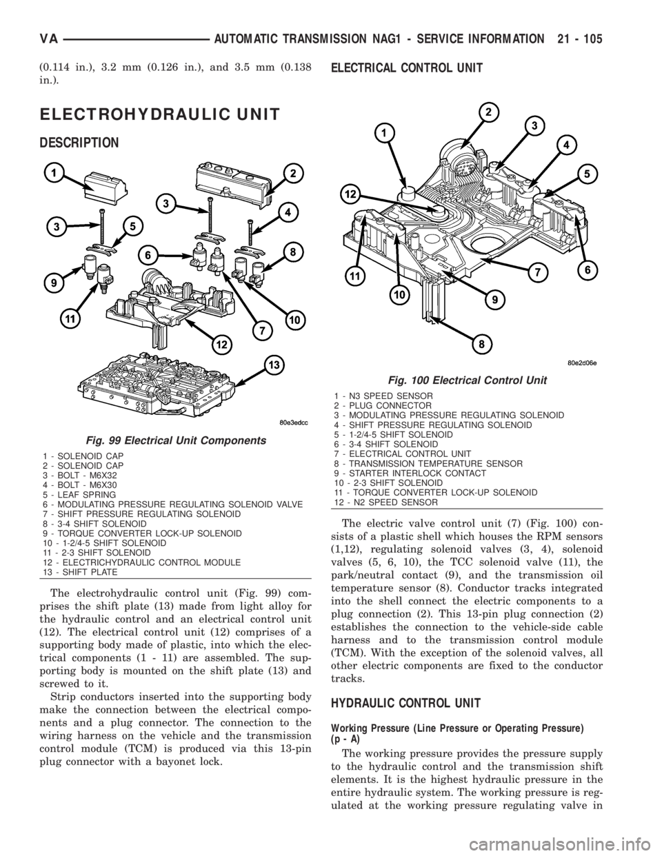
The electrohydraulic control unit (Fig. 99) com-
prises the shift plate (13) made from light alloy for
the hydraulic control and an electrical control unit
(12). The electrical control unit (12) comprises of a
supporting body made of plastic, into which the elec-
trical components (1 - 11) are assembled. The sup-
porting body is mounted on the shift plate (13) and
screwed to it.
Strip conductors inserted into the supporting body
make the connection between the electrical compo-
nents and a plug connector. The connection to the
wiring harness on the vehicle and the transmission
control module (TCM) is produced via this 13-pin
plug connector with a bayonet lock.
ELECTRICAL CONTROL UNIT
The electric valve control unit (7) (Fig. 100) con-
sists of a plastic shell which houses the RPM sensors
(1,12), regulating solenoid valves (3, 4), solenoid
valves (5, 6, 10), the TCC solenoid valve (11), the
park/neutral contact (9), and the transmission oil
temperature sensor (8). Conductor tracks integrated
into the shell connect the electric components to a
plug connection (2). This 13-pin plug connection (2)
establishes the connection to the vehicle-side cable
harness and to the transmission control module
(TCM). With the exception of the solenoid valves, all
other electric components are fixed to the conductor
tracks.
HYDRAULIC CONTROL UNIT
Working Pressure (Line Pressure or Operating Pressure)
(p-A)
The working pressure provides the pressure supply
to the hydraulic control and the transmission shift
elements. It is the highest hydraulic pressure in the
entire hydraulic system. The working pressure is reg-
ulated at the working pressure regulating valve in
Fig. 99 Electrical Unit Components
1 - SOLENOID CAP
2 - SOLENOID CAP
3 - BOLT - M6X32
4 - BOLT - M6X30
5 - LEAF SPRING
6 - MODULATING PRESSURE REGULATING SOLENOID VALVE
7 - SHIFT PRESSURE REGULATING SOLENOID
8 - 3-4 SHIFT SOLENOID
9 - TORQUE CONVERTER LOCK-UP SOLENOID
10 - 1-2/4-5 SHIFT SOLENOID
11 - 2-3 SHIFT SOLENOID
12 - ELECTRICHYDRAULIC CONTROL MODULE
13 - SHIFT PLATE
Fig. 100 Electrical Control Unit
1 - N3 SPEED SENSOR
2 - PLUG CONNECTOR
3 - MODULATING PRESSURE REGULATING SOLENOID
4 - SHIFT PRESSURE REGULATING SOLENOID
5 - 1-2/4-5 SHIFT SOLENOID
6 - 3-4 SHIFT SOLENOID
7 - ELECTRICAL CONTROL UNIT
8 - TRANSMISSION TEMPERATURE SENSOR
9 - STARTER INTERLOCK CONTACT
10 - 2-3 SHIFT SOLENOID
11 - TORQUE CONVERTER LOCK-UP SOLENOID
12 - N2 SPEED SENSOR
VAAUTOMATIC TRANSMISSION NAG1 - SERVICE INFORMATION 21 - 105
Page 1849 of 2305
relation to the load and gear. All other pressures
required for the transmission control are derived
from the working pressure.
Lubrication Pressure (p - Sm)
At the working pressure regulating valve surplus
oil is diverted to the lubrication pressure regulating
valve, from where it is used in regulated amounts to
lubricate and cool the mechanical transmission com-
ponents and the torque converter. Furthermore, the
lubrication pressure (p-Sm) is also used to limit the
pressure in the torque converter.
Shift Pressure (p - S)
The shift pressure is determined by the shift pres-
sure regulating solenoid valve and the shift pressure
regulating valve. The shift pressure:
²Regulates the pressure in the activating shift
element during the shift phase.
²Determines together with the modulating pres-
sure the pressure reduction at the deactivating shift
element as regulated by the overlap regulating valve.
²Initializes 2nd gear in limp-home mode.
Modulating Pressure (p - Mod)
The modulating pressure influences the size of the
working pressure and determines together with the
shift pressure the pressure regulated at the overlap
regulating valve. The modulating pressure is regu-
lated at the modulating pressure regulating solenoid
valve, which is under regulating valve pressure. The
modulating pressure is variable and relative to the
engine load.
Regulating Valve / Control Valve Pressure (p - RV)
The regulating valve pressure is regulated at the
regulating valve pressure regulating valve in relation
to the working pressure (p-A) up to a maximum pres-
sure of 8 bar (116 psi). It supplies the modulating
pressure regulating solenoid valve, the shift pressure
regulating solenoid valve and the shift valve pressure
regulating valve.
Shift Valve Pressure (p - SV)
The shift valve pressure (p-SV) is derived from the
regulating valve pressure (p-RV), is regulated at the
shift valve pressure regulating valve and is then
present at the:
²1-2 and 4-5 shift solenoid valve.
²3-4 shift solenoid valve.
²2-3 shift solenoid valve.
²Torque converter lockup solenoid valve.
²3-4 and 2-3 shift pressure shift valve.
The shift valve pressure (p-SV) controls the com-
mand valves via the upshift/downshift solenoid
valves.Overlap Pressure (p - š)
The overlap pressure controls the shift component
pressure reduction during a shift phase. The pres-
sure in a shift element as it disengages is controlled
during the shift phase depending on engine load
(modulating pressure) and the pressure in the shift
element as it engages. The adjusted pressure is
inversely proportional to the transmission capability
of the shift element being engaged (controlled over-
lap).
Working Pressure Regulating Valve (Operating Pressure)
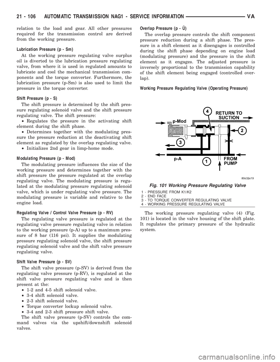
The working pressure regulating valve (4) (Fig.
101) is located in the valve housing of the shift plate.
It regulates the primary pressure of the hydraulic
system.
Fig. 101 Working Pressure Regulating Valve
1 - PRESSURE FROM K1/K2
2 - END FACE
3 - TO TORQUE CONVERTER REGULATING VALVE
4 - WORKING PRESSURE REGULATING VALVE
21 - 106 AUTOMATIC TRANSMISSION NAG1 - SERVICE INFORMATIONVA
Page 1850 of 2305
Torque Converter Lockup Clutch Regulating Valve
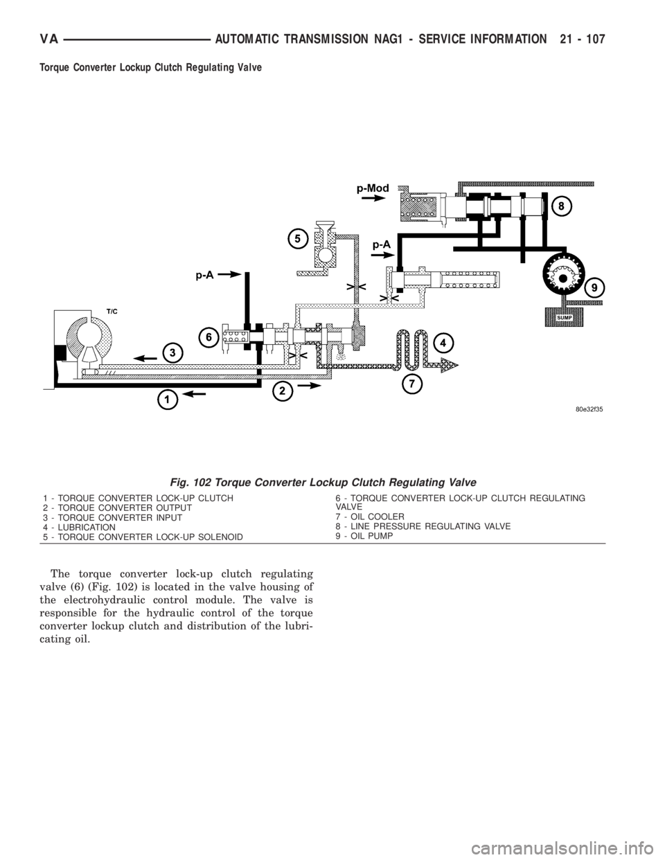
The torque converter lock-up clutch regulating
valve (6) (Fig. 102) is located in the valve housing of
the electrohydraulic control module. The valve is
responsible for the hydraulic control of the torque
converter lockup clutch and distribution of the lubri-
cating oil.
Fig. 102 Torque Converter Lockup Clutch Regulating Valve
1 - TORQUE CONVERTER LOCK-UP CLUTCH
2 - TORQUE CONVERTER OUTPUT
3 - TORQUE CONVERTER INPUT
4 - LUBRICATION
5 - TORQUE CONVERTER LOCK-UP SOLENOID6 - TORQUE CONVERTER LOCK-UP CLUTCH REGULATING
VA LV E
7 - OIL COOLER
8 - LINE PRESSURE REGULATING VALVE
9 - OIL PUMP
VAAUTOMATIC TRANSMISSION NAG1 - SERVICE INFORMATION 21 - 107
Page 1851 of 2305
Overlap Regulating Valve
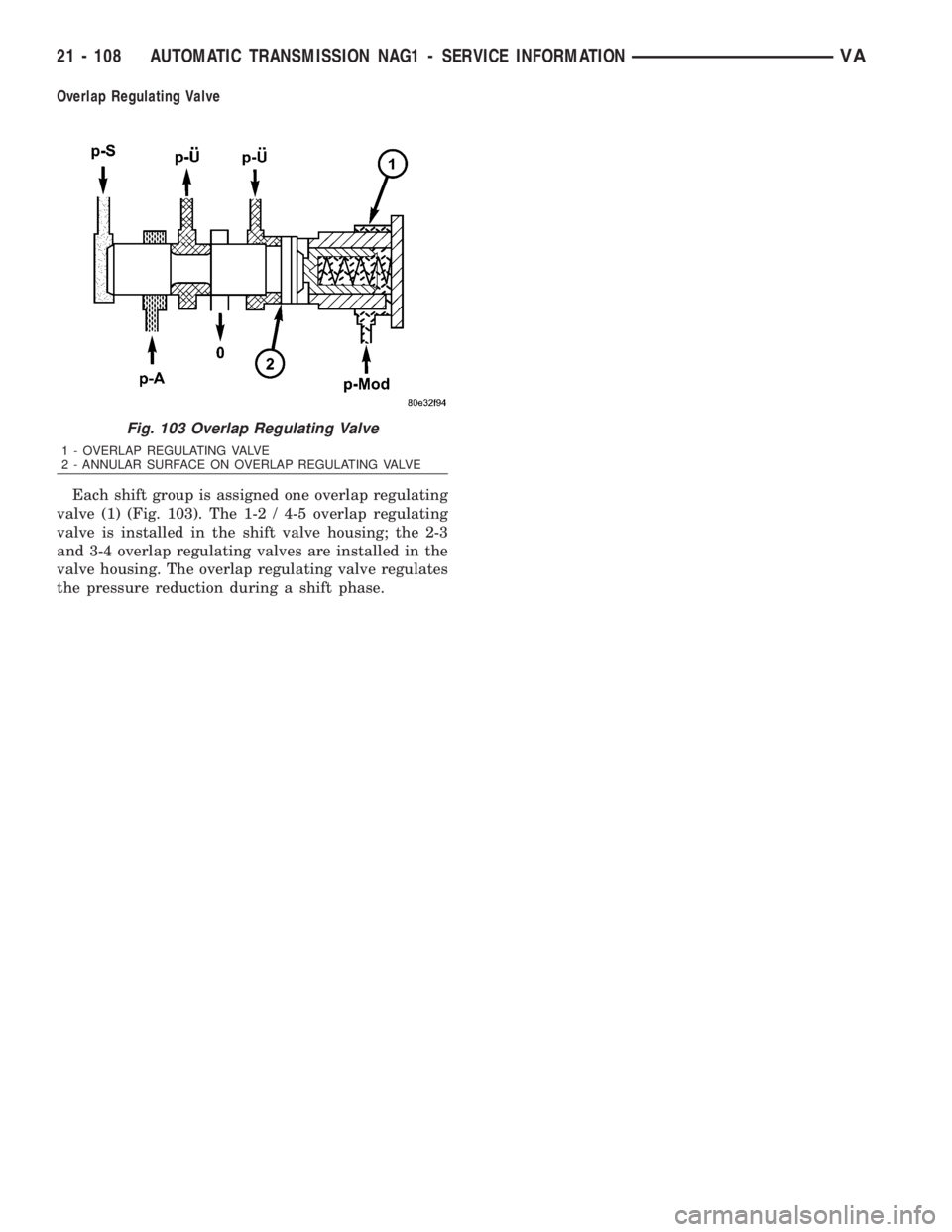
Each shift group is assigned one overlap regulating
valve (1) (Fig. 103). The 1-2 / 4-5 overlap regulating
valve is installed in the shift valve housing; the 2-3
and 3-4 overlap regulating valves are installed in the
valve housing. The overlap regulating valve regulates
the pressure reduction during a shift phase.
Fig. 103 Overlap Regulating Valve
1 - OVERLAP REGULATING VALVE
2 - ANNULAR SURFACE ON OVERLAP REGULATING VALVE
21 - 108 AUTOMATIC TRANSMISSION NAG1 - SERVICE INFORMATIONVA
Page 1852 of 2305
Command Valve
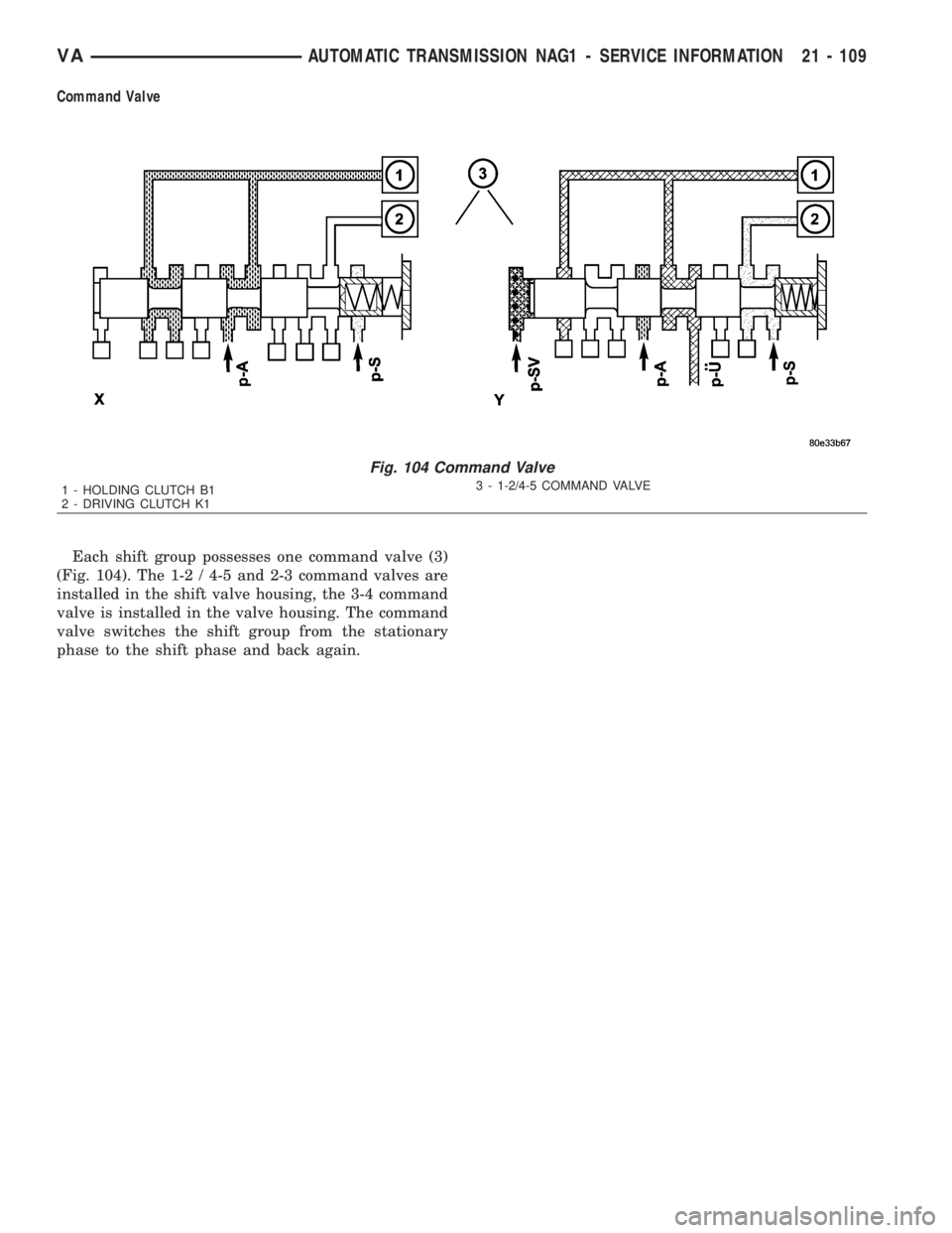
Each shift group possesses one command valve (3)
(Fig. 104). The 1-2 / 4-5 and 2-3 command valves are
installed in the shift valve housing, the 3-4 command
valve is installed in the valve housing. The command
valve switches the shift group from the stationary
phase to the shift phase and back again.
Fig. 104 Command Valve
1 - HOLDING CLUTCH B1
2 - DRIVING CLUTCH K13 - 1-2/4-5 COMMAND VALVE
VAAUTOMATIC TRANSMISSION NAG1 - SERVICE INFORMATION 21 - 109