2006 MERCEDES-BENZ SPRINTER heater
[x] Cancel search: heaterPage 645 of 2305

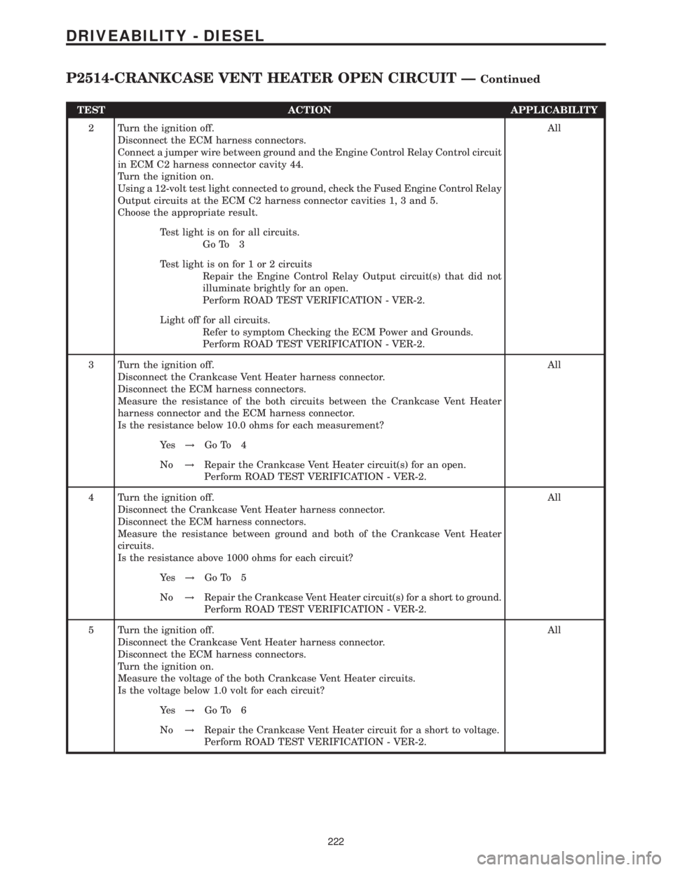
TEST ACTION APPLICABILITY
2 Turn the ignition off.
Disconnect the ECM harness connectors.
Connect a jumper wire between ground and the Engine Control Relay Control circuit
in ECM C2 harness connector cavity 44.
Turn the ignition on.
Using a 12-volt test light connected to ground, check the Fused Engine Control Relay
Output circuits at the ECM C2 harness connector cavities 1, 3 and 5.
Choose the appropriate result.All
Test light is on for all circuits.
Go To 3
Test light is on for 1 or 2 circuits
Repair the Engine Control Relay Output circuit(s) that did not
illuminate brightly for an open.
Perform ROAD TEST VERIFICATION - VER-2.
Light off for all circuits.
Refer to symptom Checking the ECM Power and Grounds.
Perform ROAD TEST VERIFICATION - VER-2.
3 Turn the ignition off.
Disconnect the Crankcase Vent Heater harness connector.
Disconnect the ECM harness connectors.
Measure the resistance of the both circuits between the Crankcase Vent Heater
harness connector and the ECM harness connector.
Is the resistance below 10.0 ohms for each measurement?All
Ye s!Go To 4
No!Repair the Crankcase Vent Heater circuit(s) for an open.
Perform ROAD TEST VERIFICATION - VER-2.
4 Turn the ignition off.
Disconnect the Crankcase Vent Heater harness connector.
Disconnect the ECM harness connectors.
Measure the resistance between ground and both of the Crankcase Vent Heater
circuits.
Is the resistance above 1000 ohms for each circuit?All
Ye s!Go To 5
No!Repair the Crankcase Vent Heater circuit(s) for a short to ground.
Perform ROAD TEST VERIFICATION - VER-2.
5 Turn the ignition off.
Disconnect the Crankcase Vent Heater harness connector.
Disconnect the ECM harness connectors.
Turn the ignition on.
Measure the voltage of the both Crankcase Vent Heater circuits.
Is the voltage below 1.0 volt for each circuit?All
Ye s!Go To 6
No!Repair the Crankcase Vent Heater circuit for a short to voltage.
Perform ROAD TEST VERIFICATION - VER-2.
222
DRIVEABILITY - DIESEL
P2514-CRANKCASE VENT HEATER OPEN CIRCUIT ÐContinued
Page 646 of 2305

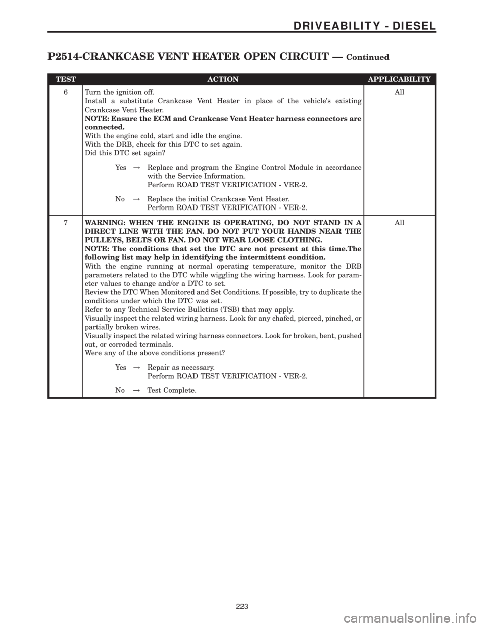
TEST ACTION APPLICABILITY
6 Turn the ignition off.
Install a substitute Crankcase Vent Heater in place of the vehicle's existing
Crankcase Vent Heater.
NOTE: Ensure the ECM and Crankcase Vent Heater harness connectors are
connected.
With the engine cold, start and idle the engine.
With the DRB, check for this DTC to set again.
Did this DTC set again?All
Ye s!Replace and program the Engine Control Module in accordance
with the Service Information.
Perform ROAD TEST VERIFICATION - VER-2.
No!Replace the initial Crankcase Vent Heater.
Perform ROAD TEST VERIFICATION - VER-2.
7WARNING: WHEN THE ENGINE IS OPERATING, DO NOT STAND IN A
DIRECT LINE WITH THE FAN. DO NOT PUT YOUR HANDS NEAR THE
PULLEYS, BELTS OR FAN. DO NOT WEAR LOOSE CLOTHING.
NOTE: The conditions that set the DTC are not present at this time.The
following list may help in identifying the intermittent condition.
With the engine running at normal operating temperature, monitor the DRB
parameters related to the DTC while wiggling the wiring harness. Look for param-
eter values to change and/or a DTC to set.
Review the DTC When Monitored and Set Conditions. If possible, try to duplicate the
conditions under which the DTC was set.
Refer to any Technical Service Bulletins (TSB) that may apply.
Visually inspect the related wiring harness. Look for any chafed, pierced, pinched, or
partially broken wires.
Visually inspect the related wiring harness connectors. Look for broken, bent, pushed
out, or corroded terminals.
Were any of the above conditions present?All
Ye s!Repair as necessary.
Perform ROAD TEST VERIFICATION - VER-2.
No!Test Complete.
223
DRIVEABILITY - DIESEL
P2514-CRANKCASE VENT HEATER OPEN CIRCUIT ÐContinued
Page 660 of 2305

TEST ACTION APPLICABILITY
8 Turn the ignition off.
Remove and inspect Fuse #16 from Fuse Block No.1
Is the fuse open?All
Ye s!Go To 9
No!Go To 11
9 Turn the ignition off.
Disconnect the ECM harness connectors.
Install a good fuse in place of Fuse #16 in Fuse Block No.1
Connect a jumper wire between ground and the Engine Control Relay Control circuit
in ECM C2 harness connector cavity 44.
Remove and inspect Fuse #16 from Fuse Block No.1.
Is the fuse open?All
Ye s!Repair the Engine Control Relay Output circuit for a short to
ground.
Perform ROAD TEST VERIFICATION - VER-2.
No!Go To 10
10 The Fuel Injectors, Crankcase Heater, Water In Fuel Sensor and related circuits can
cause Fuse #16 in Fuse Block No.1 to open. Use the Service Information Wiring
Diagrams and check these circuits/components for shorted circuits.
Were any problems found.All
Ye s!Repair or replace shorted circuit/component as necessary.
Perform ROAD TEST VERIFICATION - VER-2.
No!Replace and program the ECM in accordance with the Service
Information.
Perform ROAD TEST VERIFICATION - VER-2.
11 Turn the ignition off.
Disconnect the ECM harness connectors.
Connect a jumper wire between ground and the Engine Control Relay Control circuit
in ECM C2 harness connector cavity 44.
Turn the ignition on.
Using a 12-volt test light connected to ground, check the Fused Engine Control Relay
Output circuits at the ECM C2 harness connector cavities 1, 3 and 5.
Choose the appropriate result.All
Test light is on for all circuits.
Test Complete.
Test light is on for 1 or 2 circuits
Repair the Engine Control Relay Output circuit(s) for an open.
Perform ROAD TEST VERIFICATION - VER-2.
Light off for all circuits.
Go To 12
237
DRIVEABILITY - DIESEL
*CHECKING THE POWER AND GROUNDS ÐContinued
Page 680 of 2305

CONTROLLER ANTILOCK BRAKECAV CIRCUIT FUNCTION
1 12BR GROUND
2 12RD FUSED B(+)
3- -
4- -
5 14BR GROUND
6 14RD FUSED B(+)
7- -
8 20BK/DG SENSOR SIGNAL
9 20YL/WT SENSOR SIGNAL
10 20YL/RD SENSOR SIGNAL
11 18BL/BK K-ABS/SHIFTER ASSEMBLY
12 18BK LEFT FRONT WHEEL SPEED SENSOR (+)
13 - -
14 20WT LEFT REAR WHEEL SPEED SENSOR (+)
15 18BR RIGHT FRONT WHEEL SPEED SENSOR (-)
16 18BK RIGHT FRONT WHEEL SPEED SENSOR (+)
17 - -
18 - -
19 - -
20 20WT BRAKE SWITCH OUTPUT
21 20BR GROUND
22 - -
23 18BK/RD FUSED OPTIONAL EQUIPMENT RELAY OUTPUT
24 20DG/WT CAN C BUS (+)
25 20BR SENSOR GROUND
26 20WT/GY BRAKE PRESSURE SENSOR SIGNAL
27 18BK/BL TCS SWITCH (ASR) SENSE
28 18BR LEFT FRONT WHEEL SPEED SENSOR (-)
29 20BR LEFT REAR WHEEL SPEED SENSOR (-)
30 20BR RIGHT REAR WHEEL SPEED SENSOR (-)
31 20YL RIGHT REAR WHEEL SPEED SENSOR (+)
32 18BK/RD BRAKE LAMP SWITCH OUTPUT
33 - -
34 - -
35 - -
36 - -
37 - -
38 - -
39 20RD/BL POWER INPUT
40 20DG CAN C BUS (-)
41 20DG/YL SENSOR SIGNAL
42 20WT/RD 5 VOLT SUPPLY
CRANKCASE HEATER - BLACKCAV CIRCUIT FUNCTION
1 18BR (EXCEPT OBD) GROUND
1 18BK/RD (OBD) CRANKCASE HEATER SIGNAL
2 16BK/RD (EXCEPT OBD) FUSED ENGINE CONTROL RELAY OUTPUT
2 18BK/BR (OBD) CRANKCASE HEATER GROUND
C
O
N
N
E
C
T
O
R
P
I
N
O
U
T
S
257
CONNECTOR PINOUTS
Page 682 of 2305

ENGINE CONTROL MODULE C1 (OBD)CAV CIRCUIT FUNCTION
1 16BL FUEL INJECTOR NO. 1 HIGH-SIDE CONTROL
2 16BL/WT FUEL INJECTOR NO. 4 HIGH-SIDE CONTROL
3 16DG FUEL INJECTOR NO. 3 HIGH-SIDE CONTROL
4 20RD/WT FUEL PRESSURE SOLENOID 12 VOLT SUPPLY
8 18BL/GY FUEL TEMPERATURE SENSOR SIGNAL
10 20RD/YL ENGINE OIL SENSOR 5 VOLT SUPPLY
11 20GY/BL ENGINE OIL SENSOR SIGNAL
12 20BR/RD INTAKE PRESSURE SENSOR GROUND
13 20VT/DG INTAKE PRESSURE SENSOR SIGNAL
14 20BR/DG CAMSHAFT POSITION SENSOR GROUND
15 20DG/BK O2 1/1 PUMP CELL SIGNAL
20 18BK/YL WATER IN FUEL SENSOR SIGNAL
21 18BK/RD CRANKCASE HEATER SIGNAL
25 16BK FUEL INJECTOR NO. 2 HIGH-SIDE CONTROL
26 16BK/WT FUEL INJECTOR NO. 5 HIGH-SIDE CONTROL
28 18RD/BK FUEL QUANTITY SOLENOID 12 VOLT SUPPLY
31 20YL/BL MASS AIR FLOW SENSOR GROUND
32 18DG/BK FUEL TEMPERATURE SENSOR GROUND
35 20BR/BK SENSOR GROUND
36 20VT/RD INTAKE PRESSURE SENSOR 5 VOLT SUPPLY
37 20RD/BL CAMSHAFT POSITION SENSOR 5 VOLT SUPPLY
38 20YL/GY CAMSHAFT POSITION SENSOR SIGNAL
39 20GY O2 1/1 SENSOR CELL SIGNAL
40 20GY/WT O2 1/1 VIRTUAL GROUND
49 16BK/VT FUEL INJECTOR NO. 4 LOW-SIDE CONTROL
50 16BK/DG FUEL INJECTOR NO. 3 LOW-SIDE CONTROL
51 16BK/YL FUEL INJECTOR NO. 5 LOW-SIDE CONTROL
52 20BK/WT FUEL PRESSURE SOLENOID CONTROL
55 18BR WATER IN FUEL SENSOR GROUND
56 20BR/WT ENGINE COOLANT TEMPERATURE SENSOR GROUND
57 20DG/RD ENGINE COOLANT TEMPERATURE SENSOR SIGNAL
59 20DG/VT FUEL PRESSURE SENSOR SIGNAL
61 20BR/VT MASS AIR FLOW SENSOR 5 VOLT SUPPLY
62 20DG/YL O2 1/1 PUMP CELL CONTROL
72 20GY/BL O2 1/1 HEATER CONTROL
73 16BK/RD FUEL INJECTOR NO. 1 LOW-SIDE CONTROL
74 16BK/BL FUEL INJECTOR NO. 2 LOW-SIDE CONTROL
76 18BR/YL FUEL QUANTITY SOLENOID CONTROL
79 18BR/RD WATER IN FUEL SENSOR 12 VOLT SUPPLY
84 20BR/GY FUEL PRESSURE SENSOR GROUND
85 20YL/DG MASS AIR FLOW SENSOR SIGNAL
86 20RD/DG FUEL PRESSURE SENSOR 5 VOLT SUPPLY
87 20DG/WT CRANKSHAFT POSITION SENSOR SIGNAL NO. 1
88 20DG CRANKSHAFT POSITION SENSOR SIGNAL NO. 2
90 20DG/WT EGR VALVE CONTROL
91 18BK/BR CRANKCASE HEATER GROUND
93 16YL/DG BOOST PRESSURE SERVOMOTOR CONTROL
C
O
N
N
E
C
T
O
R
P
I
N
O
U
T
S
259
CONNECTOR PINOUTS
Page 694 of 2305

KICK DOWN SWITCH - BLACKCAV CIRCUIT FUNCTION
1 18BR/DG KICKDOWN SWITCH SIGNAL
2 18BR (EXCEPT OBD) SENSOR GROUND
2 18BR (OBD) GROUND
MASS AIR FLOW SENSOR - BLACKCAV CIRCUIT FUNCTION
1 16YL/RD (OBD) FUSED IGNITION SWITCH OUTPUT (RUN-START)
2 20YL/RD (EXCEPT OBD) MASS AIR FLOW SENSOR 12 VOLT SUPPLY
2 20BR/VT (OBD) MASS AIR FLOW SENSOR 5 VOLT SUPPLY
3 20BR/YL (EXCEPT OBD) MASS AIR FLOW SENSOR GROUND
3 20YL/BL (OBD) MASS AIR FLOW SENSOR GROUND
4 20BR/BK (EXCEPT OBD) MASS AIR FLOW SENSOR 5 VOLT SUPPLY
4 20YL/DG (OBD) MASS AIR FLOW SENSOR SIGNAL
5 20YL/DG (EXCEPT OBD) MASS AIR FLOW SENSOR SIGNAL
OXYGEN SENSOR (OBD)CAV CIRCUIT FUNCTION
1 20DG/BK O2 1/1 PUMP CELL SIGNAL
2 20GY/WT O2 1/1 VIRTUAL GROUND
3 20GY/BL O2 1/1 HEATER CONTROL
4 20RD/DG FUSED ENGINE CONTROL RELAY OUTPUT
5 20DG/YL O2 1/1 PUMP CELL CONTROL
6 20GY O2 1/1 SENSOR CELL SIGNAL
C
O
N
N
E
C
T
O
R
P
I
N
O
U
T
S
271
CONNECTOR PINOUTS
Page 719 of 2305

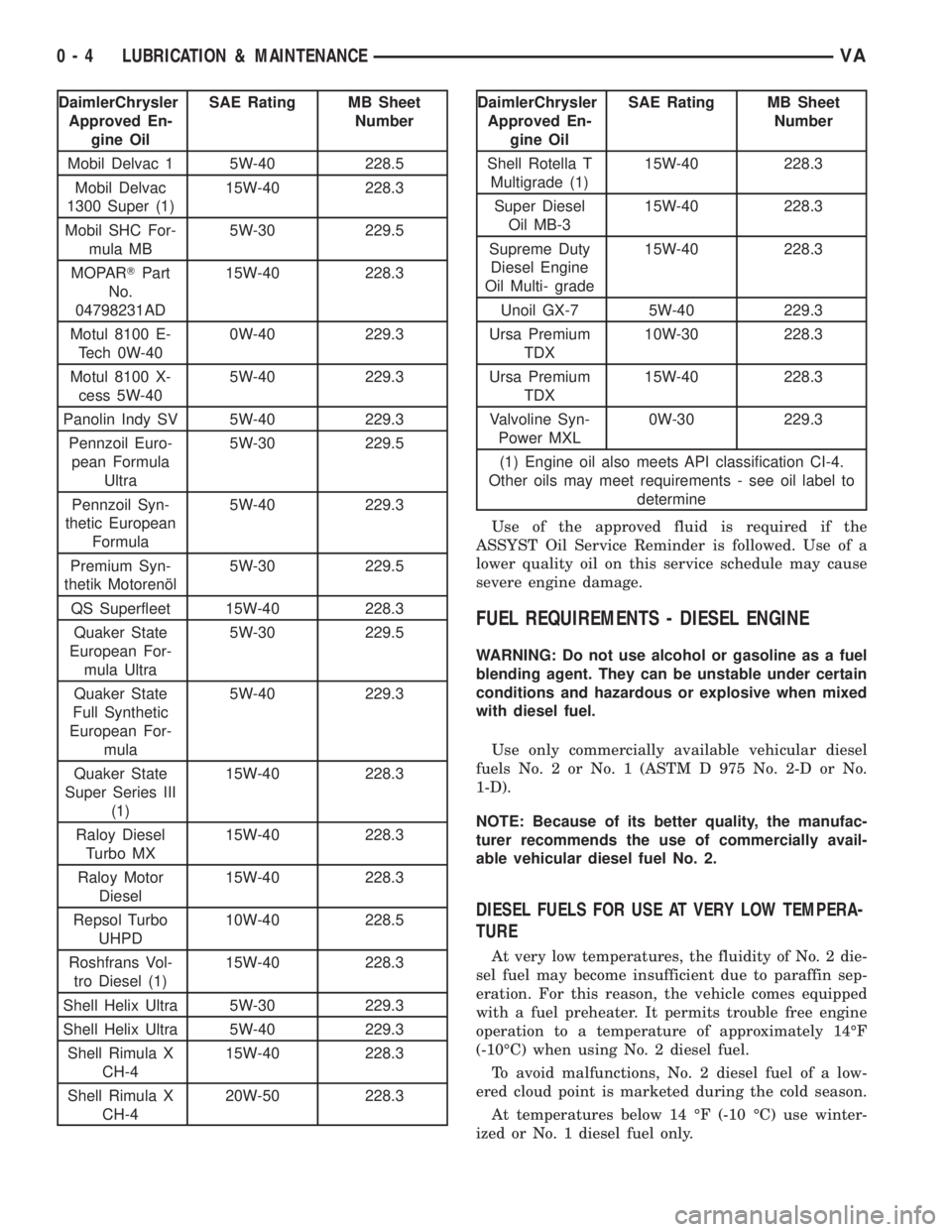
DaimlerChrysler
Approved En-
gine OilSAE Rating MB Sheet
Number
Mobil Delvac 1 5W-40 228.5
Mobil Delvac
1300 Super (1)15W-40 228.3
Mobil SHC For-
mula MB5W-30 229.5
MOPARTPart
No.
04798231AD15W-40 228.3
Motul 8100 E-
Tech 0W-400W-40 229.3
Motul 8100 X-
cess 5W-405W-40 229.3
Panolin Indy SV 5W-40 229.3
Pennzoil Euro-
pean Formula
Ultra5W-30 229.5
Pennzoil Syn-
thetic European
Formula5W-40 229.3
Premium Syn-
thetik Motorenæl5W-30 229.5
QS Superfleet 15W-40 228.3
Quaker State
European For-
mula Ultra5W-30 229.5
Quaker State
Full Synthetic
European For-
mula5W-40 229.3
Quaker State
Super Series III
(1)15W-40 228.3
Raloy Diesel
Turbo MX15W-40 228.3
Raloy Motor
Diesel15W-40 228.3
Repsol Turbo
UHPD10W-40 228.5
Roshfrans Vol-
tro Diesel (1)15W-40 228.3
Shell Helix Ultra 5W-30 229.3
Shell Helix Ultra 5W-40 229.3
Shell Rimula X
CH-415W-40 228.3
Shell Rimula X
CH-420W-50 228.3DaimlerChrysler
Approved En-
gine OilSAE Rating MB Sheet
Number
Shell Rotella T
Multigrade (1)15W-40 228.3
Super Diesel
Oil MB-315W-40 228.3
Supreme Duty
Diesel Engine
Oil Multi- grade15W-40 228.3
Unoil GX-7 5W-40 229.3
Ursa Premium
TDX10W-30 228.3
Ursa Premium
TDX15W-40 228.3
Valvoline Syn-
Power MXL0W-30 229.3
(1) Engine oil also meets API classification CI-4.
Other oils may meet requirements - see oil label to
determine
Use of the approved fluid is required if the
ASSYST Oil Service Reminder is followed. Use of a
lower quality oil on this service schedule may cause
severe engine damage.
FUEL REQUIREMENTS - DIESEL ENGINE
WARNING: Do not use alcohol or gasoline as a fuel
blending agent. They can be unstable under certain
conditions and hazardous or explosive when mixed
with diesel fuel.
Use only commercially available vehicular diesel
fuels No. 2 or No. 1 (ASTM D 975 No. 2-D or No.
1-D).
NOTE: Because of its better quality, the manufac-
turer recommends the use of commercially avail-
able vehicular diesel fuel No. 2.
DIESEL FUELS FOR USE AT VERY LOW TEMPERA-
TURE
At very low temperatures, the fluidity of No. 2 die-
sel fuel may become insufficient due to paraffin sep-
eration. For this reason, the vehicle comes equipped
with a fuel preheater. It permits trouble free engine
operation to a temperature of approximately 14ÉF
(-10ÉC) when using No. 2 diesel fuel.
To avoid malfunctions, No. 2 diesel fuel of a low-
ered cloud point is marketed during the cold season.
At temperatures below 14 ÉF (-10 ÉC) use winter-
ized or No. 1 diesel fuel only.
0 - 4 LUBRICATION & MAINTENANCEVA
Page 829 of 2305

COOLING SYSTEM
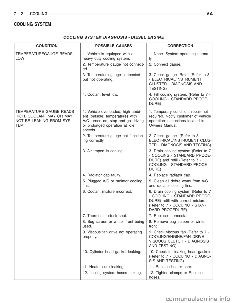
COOLING SYSTEM DIAGNOSIS - DIESEL ENGINE
CONDITION POSSIBLE CAUSES CORRECTION
TEMPERATUREGAUGE READS
LOW1. Vehicle is equipped with a
heavy duty cooling system.1. None. System operating norma-
ly.
2. Temperature gauge not connect-
ed2. Connect gauge.
3. Temperature gauge connected
but not operating.3. Check gauge. Refer (Refer to 8
- ELECTRICAL/INSTRUMENT
CLUSTER - DIAGNOSIS AND
TESTING)
4. Coolant level low. 4. Fill cooling system. (Refer to 7 -
COOLING - STANDARD PROCE-
DURE)
TEMPERATURE GAUGE READS
HIGH. COOLANT MAY OR MAY
NOT BE LEAKING FROM SYS-
TEM1. Vehicle overloaded, high ambi-
ent (outside) temperatures with
A/C turned on, stop and go driving
or prolonged operation at idle
speeds.1. Temporary condition, repair not
required. Notify customer of vehicle
operation instructions located in
Owners Manual.
2. Temperature gauge not function-
ing correctly.2. Check gauge. (Refer to 8 -
ELECTRICAL/INSTRUMENT CLUS-
TER - DIAGNOSIS AND TESTING)
3. Air traped in cooling 3. Drain cooling system (Refer to 7
- COOLING - STANDARD PROCE-
DURE) and refill (Refer to 7 -
COOLING - STANDARD PROCE-
DURE)
4. Radiator cap faulty. 4. Replace radiator cap.
5. Plugged A/C or radiator cooling
fins.5. Clean all debre away from A/C
and radiator cooling fins.
6. Coolant mixture incorrect. 6. Drain cooling system (Refer to 7
- COOLING - STANDARD PROCE-
DURE) refill with correct mixture
(Refer to 7 - COOLING - STAN-
DARD PROCEDURE).
7. Thermostat stuck shut. 7. Replace thermostat.
8. Bug screen or winter front being
used.8. Remove bug screen or winter
front.
9. Viscous fan drive not operating
properly.9. Check viscous fan (Refer to 7 -
COOLING/ENGINE/FAN DRIVE
VISCOUS CLUTCH - DIAGNOSIS
AND TESTING)
10. Cylinder head gasket leaking. 10. Check for leaking head gaskets
(Refer to 7 - COOLING - DIAGNO-
SIS AND TESTING).
11. Heater core leaking. 11. Replace heater core.
12. cooling system hoses leaking. 12. Tighten clamps or Replace
hoses.
7 - 2 COOLINGVA