2006 MERCEDES-BENZ SPRINTER set clock
[x] Cancel search: set clockPage 16 of 2305
When supplied with the proper electrical signal, the
inflator discharged the gas directly into the cush-
ion. The airbag cannot be repaired, and must be
replaced if deployed or in any way damaged.
WARNING: THE DRIVER AIRBAG MODULE
CONTAINS ARGON GAS PRESSURIZED TO
OVER 17236.89 Kpa (2500 PSI). DO NOT
ATTEMPT TO DISMANTLE AN AIRBAG
MODULE OR TAMPER WITH ITS INFLATOR.
DO NOT PUNCTURE, INCINERATE, OR
BRING INTO CONTACT WITH ELECTRICITY.
DO NOT STORE AT TEMPERATURE
EXCEEDING 93ÉC (200ÉF). REPLACE AIRBAG
SYSTEM COMPONENTS ONLY WITH PARTS
SPECIFIED IN THE CHRYSLER MOPAR
PARTS CATALOG. SUBSTITUTE PARTS MAY
APPEAR INTER-CHANGEABLE, BUT
INTERNAL DIFFERENCES MAY RESULT IN
INFERIOR OCCUPANT PROTECTION. THE
FASTENERS, SCREWS, AND BOLTS
ORIGINALLY USED FOR THE AIRBAG
SYSTEM COMPONENTS HAVE SPECIAL
COATINGS AND ARE SPECIFICALLY
DESIGNED FOR THE AIRBAG SYSTEM. THEY
MUST NEVER BE REPLACED WITH ANY
SUBSTITUTES. ANY TIME A NEW FASTENER
IS NEEDED, REPLACE IT WITH THE
CORRECT FASTENERS PROVIDED IN THE
SERVICE PACKAGE OR SPECIFIED IN THE
MOPAR PARTS CATALOG. FAILURE TO
TAKE THE PROPER PRECAUTIONS COULD
RESULT IN ACCIDENTAL AIRBAG
DEPLOYMENT AND PERSONAL INJURY OR
DEATH.
3.1.2 CLOCKSPRING
The clockspring is mounted on the steering col-
umn under the steering wheel. This assembly con-
sists of a plastic housing which contains a flat,
ribbon-like, electrically conductive tape that winds
and unwinds with the steering wheel rotation. The
clockspring is used to maintain a continuous elec-
trical circuit between the instrument panel wiring
and the driver airbag and the horn. The clockspring
must be properly centered when it is reinstalled on
the steering column following any service proce-
dure, or it could be damaged. The clockspring can-
not be repaired and it must be replaced.
3.1.3 PASSENGER AIRBAG
The Passenger Airbag is optional equipment.
When supplied with the proper electrical signal the
passenger airbag inflator discharges the gas di-rectly into the cushion. The airbag module cannot
be repaired, and must be replaced if deployed or in
any way damaged.
WARNING: THE PASSENGER AIRBAG
MODULE CONTAINS ARGON GAS
PRESSURIZED TO 17236.89 Kpa (2500 PSI).
DO NOT ATTEMPT TO DISMANTLE AN
AIRBAG MODULE OR TAMPER WITH ITS
INFLATOR. DO NOT PUNCTURE,
INCINERATE, OR BRING INTO CONTACT
WITH ELECTRICITY. DO NOT STORE AT
TEMPERATURE EXCEEDING 93ÉC (200ÉF).
REPLACE AIRBAG SYSTEM COMPONENTS
ONLY WITH PARTS SPECIFIED IN THE
MOPAR PARTS CATALOG. SUBSTITUTE
PARTS MAY APPEAR INTER-CHANGEABLE,
BUT INTERNAL DIFFERENCES MAY RESULT
IN INFERIOR OCCUPANT PROTECTION. THE
FASTENERS, SCREWS, AND BOLTS
ORIGINALLY USED FOR THE AIRBAG
SYSTEM COMPONENTS HAVE SPECIAL
COATINGS AND ARE SPECIFICALLY
DESIGNED FOR THE AIRBAG SYSTEM. THEY
MUST NEVER BE REPLACED WITH ANY
SUBSTITUTES. ANY TIME A NEW FASTENER
IS NEEDED, REPLACE IT WITH THE
CORRECT FASTENERS PROVIDED IN THE
SERVICE PACKAGE OR SPECIFIED IN THE
MOPAR PARTS CATALOG. FAILURE TO
TAKE THE PROPER PRECAUTIONS COULD
RESULT IN ACCIDENTAL AIRBAG
DEPLOYMENT AND PERSONAL INJURY OR
DEATH.
3.1.4 SEAT BELT TENSIONERS
Front seat belt systems incorporate a Driver and
optional Passenger Seat Belt Tensioner Retractors.
At the onset of an impact event each tensioner uses
a pyrotechnic device, which is triggered simulta-
neously with the front airbags, to rapidly retract
the seat belts. With the slack removed, the occu-
pant's forward motion in an impact will be reduced
as will the likelihood of contacting interior compo-
nents. After an impact that deploys the airbag, the
seat belt tensioner assembly must be replaced. The
ACM module monitors the Seat Belt Tensioners
circuit resistance and reports active and stored
DTCs if any problem is found. Follow all of the
safety procedures when servicing tensioner.
3.1.5 SPECIAL TOOLS
Airbag load tools 8310 and 8443 are used in some
airbag diagnostic test. The load tools contain fixed
resistive loads, jumpers and adapters. The fixed
3
GENERAL INFORMATION
Page 46 of 2305
Symptom:
DRIVER SQUIB 1 CIRCUIT OPEN
When Monitored and Set Condition:
DRIVER SQUIB 1 CIRCUIT OPEN
When Monitored: With the ignition on, the ACM monitors the resistance of the Driver
Squib 1 circuits.
Set Condition: The ACM detects an open circuit or high resistance in the Driver Squib 1
circuits.
POSSIBLE CAUSES
DRIVER AIRBAG SQUIB 1 CIRCUIT OPEN
CLOCKSPRING SQUIB 1 CIRCUIT OPEN
DRIVER SQUIB 1 LINE 1 OR LINE 2 CIRCUITS OPEN
ACM, DRIVER SQUIB 1 CIRCUIT OPEN
STORED CODE OR INTERMITTENT CONDITION
ACTIVE CODE PRESENT
TEST ACTION APPLICABILITY
1 Turn the ignition on.
NOTE: Ensure the battery is fully charged.
NOTE: For the purpose of this test, the AECM and ORC modules will be
referred to as an ACM.
SELECT ACTIVE or STORED DTC:All
ACM - ACTIVE DTC
Go To 2
ACM - STORED DTC
Go To 6
NOTE: When reconnecting Airbag system components, the ignition must be
turned off and the battery must be disconnected.
33
AIRBAG
Page 49 of 2305
Symptom:
DRIVER SQUIB 1 CIRCUIT SHORT
When Monitored and Set Condition:
DRIVER SQUIB 1 CIRCUIT SHORT
When Monitored: With the ignition on, the ACM monitors the resistance of the Driver
Squib 1 circuits.
Set Condition: The ACM has detected low resistance on the Driver Squib 1 circuits.
POSSIBLE CAUSES
DRIVER AIRBAG SQUIB 1 CIRCUIT SHORT
CLOCKSPRING, DRIVER SQUIB 1 CIRCUITS SHORT
DRIVER AIRBAG SQUIB 1 LINE 1 SHORT TO LINE 2
ACM, DRIVER SQUIB LINE 1 SHORT TO LINE 2
STORED CODE OR INTERMITTENT CONDITION
ACTIVE CODE PRESENT
TEST ACTION APPLICABILITY
1 Turn the ignition on.
NOTE: Ensure the battery is fully charged.
NOTE: For the purpose of this test, the AECM and ORC modules will be
referred to as an ACM.
SELECT ACTIVE or STORED DTC:All
ACM - ACTIVE DTC
Go To 2
ACM - STORED DTC
Go To 6
NOTE: When reconnecting airbag system components the Ignition must be
turned off and the Battery must be disconnected.
36
AIRBAG
Page 52 of 2305
Symptom:
DRIVER SQUIB 1 SHORT TO BATTERY
When Monitored and Set Condition:
DRIVER SQUIB 1 SHORT TO BATTERY
When Monitored: With the ignition on, the ACM monitors the voltage of the Driver Squib
1 circuits.
Set Condition: The ACM has detected high voltage on the Driver Squib 1 circuits.
POSSIBLE CAUSES
DRIVER AIRBAG SQUIB 1 SHORT TO BATTERY
CLOCKSPRING, DRIVER SQUIB 1 SHORT TO BATTERY
DRIVER SQUIB 1 LINE 1 OR LINE 2 SHORT TO BATTERY
ACM, DRIVER SQUIB 1 SHORT TO BATTERY
STORED CODE OR INTERMITTENT CONDITION
ACTIVE CODE PRESENT
TEST ACTION APPLICABILITY
1 Turn the ignition on.
NOTE: Ensure the battery is fully charged.
NOTE: For the purpose of this test, the AECM and ORC modules will be
referred to as an ACM.
SELECT ACTIVE or STORED ACM DTC:All
ACM - ACTIVE DTC
Go To 2
ACM - STORED DTC
Go To 5
NOTE: When reconnecting Airbag system components, the ignition must be
turned off and the battery must be disconnected.
39
AIRBAG
Page 54 of 2305
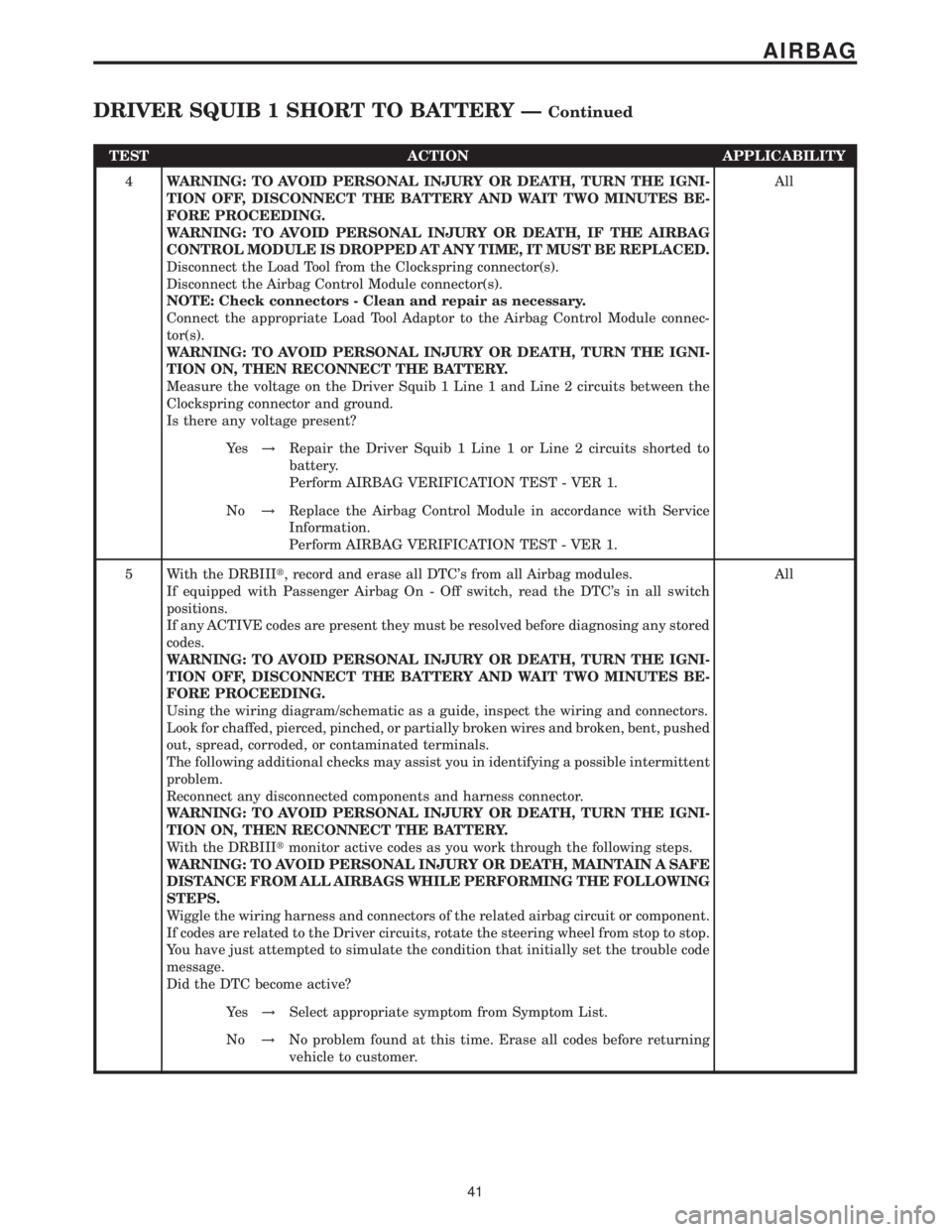
TEST ACTION APPLICABILITY
4WARNING: TO AVOID PERSONAL INJURY OR DEATH, TURN THE IGNI-
TION OFF, DISCONNECT THE BATTERY AND WAIT TWO MINUTES BE-
FORE PROCEEDING.
WARNING: TO AVOID PERSONAL INJURY OR DEATH, IF THE AIRBAG
CONTROL MODULE IS DROPPED AT ANY TIME, IT MUST BE REPLACED.
Disconnect the Load Tool from the Clockspring connector(s).
Disconnect the Airbag Control Module connector(s).
NOTE: Check connectors - Clean and repair as necessary.
Connect the appropriate Load Tool Adaptor to the Airbag Control Module connec-
tor(s).
WARNING: TO AVOID PERSONAL INJURY OR DEATH, TURN THE IGNI-
TION ON, THEN RECONNECT THE BATTERY.
Measure the voltage on the Driver Squib 1 Line 1 and Line 2 circuits between the
Clockspring connector and ground.
Is there any voltage present?All
Ye s!Repair the Driver Squib 1 Line 1 or Line 2 circuits shorted to
battery.
Perform AIRBAG VERIFICATION TEST - VER 1.
No!Replace the Airbag Control Module in accordance with Service
Information.
Perform AIRBAG VERIFICATION TEST - VER 1.
5 With the DRBIIIt, record and erase all DTC's from all Airbag modules.
If equipped with Passenger Airbag On - Off switch, read the DTC's in all switch
positions.
If any ACTIVE codes are present they must be resolved before diagnosing any stored
codes.
WARNING: TO AVOID PERSONAL INJURY OR DEATH, TURN THE IGNI-
TION OFF, DISCONNECT THE BATTERY AND WAIT TWO MINUTES BE-
FORE PROCEEDING.
Using the wiring diagram/schematic as a guide, inspect the wiring and connectors.
Look for chaffed, pierced, pinched, or partially broken wires and broken, bent, pushed
out, spread, corroded, or contaminated terminals.
The following additional checks may assist you in identifying a possible intermittent
problem.
Reconnect any disconnected components and harness connector.
WARNING: TO AVOID PERSONAL INJURY OR DEATH, TURN THE IGNI-
TION ON, THEN RECONNECT THE BATTERY.
With the DRBIIItmonitor active codes as you work through the following steps.
WARNING: TO AVOID PERSONAL INJURY OR DEATH, MAINTAIN A SAFE
DISTANCE FROM ALL AIRBAGS WHILE PERFORMING THE FOLLOWING
STEPS.
Wiggle the wiring harness and connectors of the related airbag circuit or component.
If codes are related to the Driver circuits, rotate the steering wheel from stop to stop.
You have just attempted to simulate the condition that initially set the trouble code
message.
Did the DTC become active?All
Ye s!Select appropriate symptom from Symptom List.
No!No problem found at this time. Erase all codes before returning
vehicle to customer.
41
AIRBAG
DRIVER SQUIB 1 SHORT TO BATTERY ÐContinued
Page 55 of 2305
Symptom:
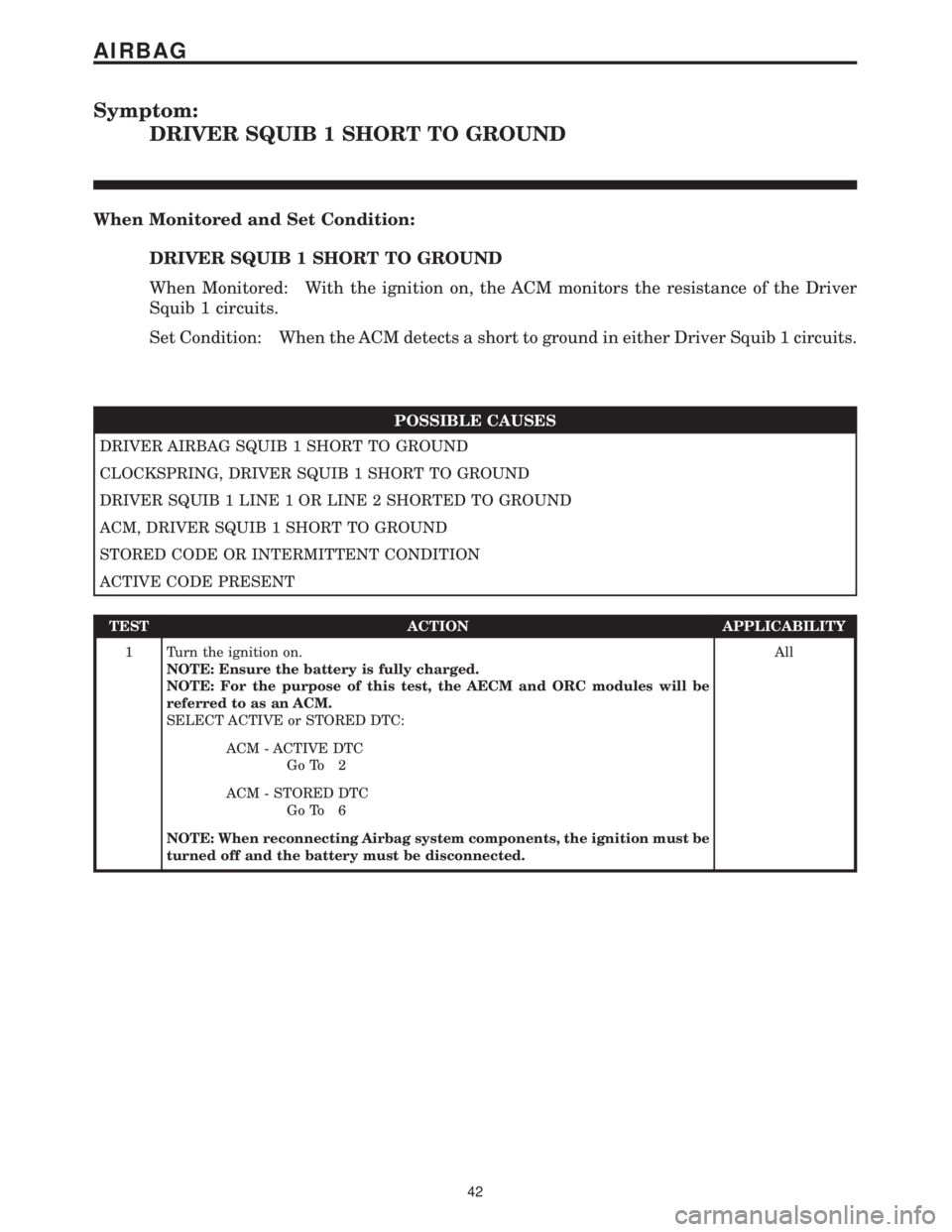
DRIVER SQUIB 1 SHORT TO GROUND
When Monitored and Set Condition:
DRIVER SQUIB 1 SHORT TO GROUND
When Monitored: With the ignition on, the ACM monitors the resistance of the Driver
Squib 1 circuits.
Set Condition: When the ACM detects a short to ground in either Driver Squib 1 circuits.
POSSIBLE CAUSES
DRIVER AIRBAG SQUIB 1 SHORT TO GROUND
CLOCKSPRING, DRIVER SQUIB 1 SHORT TO GROUND
DRIVER SQUIB 1 LINE 1 OR LINE 2 SHORTED TO GROUND
ACM, DRIVER SQUIB 1 SHORT TO GROUND
STORED CODE OR INTERMITTENT CONDITION
ACTIVE CODE PRESENT
TEST ACTION APPLICABILITY
1 Turn the ignition on.
NOTE: Ensure the battery is fully charged.
NOTE: For the purpose of this test, the AECM and ORC modules will be
referred to as an ACM.
SELECT ACTIVE or STORED DTC:All
ACM - ACTIVE DTC
Go To 2
ACM - STORED DTC
Go To 6
NOTE: When reconnecting Airbag system components, the ignition must be
turned off and the battery must be disconnected.
42
AIRBAG
Page 723 of 2305
effect panels. If necessary, remove the wheels from
the lifted end of the vehicle and lower the vehicle
closer to the ground, to increase the ground clearance
at the opposite end of the vehicle. Install lug nuts on
wheel attaching studs to retain brake drums.
RAMP ANGLE
If a vehicle with flat-bed towing equipment is used,
the approach ramp angle should not exceed 15
degrees.
TOWING WHEN KEYS ARE NOT AVAILABLE
When the vehicle is locked and keys are not avail-
able, use a flat bed hauler. A Wheel-lift or Sling-type
device can be used provided all the wheels are lifted
off the ground using tow dollies.
MAINTENANCE SCHEDULES
DESCRIPTION
The use of special lubricant additives is not recom-
mended. The use of such additives may affect the
warranty rights. With regard to legal stipulations
concerning emissions control, please note that
engines have to be serviced and adjusted in accor-
dance with special instructions and using special
measuring equipment. Modifications to or interfer-
ence with the emissions control systems are not per-
missible.
MAINTENANCE - WITHOUT ASSYST MAINTE-
NANCE COMPUTER
Maintenance Intervals
²Oil service ±Normal Operationevery 10,000
miles or 16,000 km or 12 months.
²Maintenance service every 30,000 miles or
48,000 km.
Additional work must be carried out at yearly
intervals.
MAINTENANCE - WITH ASSYST MAINTENANCE
COMPUTER
ASSYST provides information on the best possible
timing for maintenance work.
When the next maintenance service is due, this
will be indicated in the multi-function display with
the wrench icon symbol displayed in km/miles or
days.
²One wrench icon showing indicates Oil Service
is necessary.
²Two wrench icons showing indicates Mainte-
nance Service is necessary ± displayed in km/miles or
days.
If the display shows the number of days, a clock
symbol will also appear in the multi-function display.You should have the maintenance performed
within the stated period/distance.
The service indicator will be reset after an oil ser-
vice and/or maintenance service has been performed.
REGULAR CHECK - UPS
To maintain the safe operation of the vehicle, it is
recommended that the following tasks be performed
on a regular basis (i.e. weekly or whenever the vehi-
cle is refueled). Check:
²Engine oil level
²Brake system - fluid level
²Battery - acid level
²Windshield washer system and headlamp clean-
ing system - fluid level
²Mechanical assemblies (e.g. engine, transmis-
sion, etc.) - check for leaks
²Condition of tires and tires pressures
²All exterior lights
SPECIAL MAINTENANCE REQUIREMENTS
If bodies built by manufacturers other than
DaimlerChrysler Corporation are fitted to the vehi-
cle, the maintenance requirements and lubrication
intervals specified by the body manufacturer must be
adhered to, in addition to all standard maintenance
requirements.
Coolant
Corrosion inhibitor/antifreeze concentration in the
coolant should be checked before the onset of winter
(once year in countries with high prevailing temper-
atures).
Replace the coolant every five years or 100,000
miles.
Dust Filter for Heating / Ventilation Replacement
The dust filter and the tailgate interior filter are to
be renewed during routine maintenance service. If
operating conditions are dusty, these filters should be
renewed more frequently.
ENGINE OIL CHANGE AND FILTER REPLACEMENT
At a minimum, change the engine oil and oil filter
once a year ± even if the vehicle mileage per year is
extremely low. For standard oil service schedules
refer to the chapter oil service and maintenance ser-
vice.
Once a Year
Select the viscosity of the engine oil (SAE classes)
according to the outside air temperature.
Only use engine oil approved by DaimlerChrysler
Corporation if following the ASSYST system guide-
lines.
0 - 8 LUBRICATION & MAINTENANCEVA
Page 875 of 2305
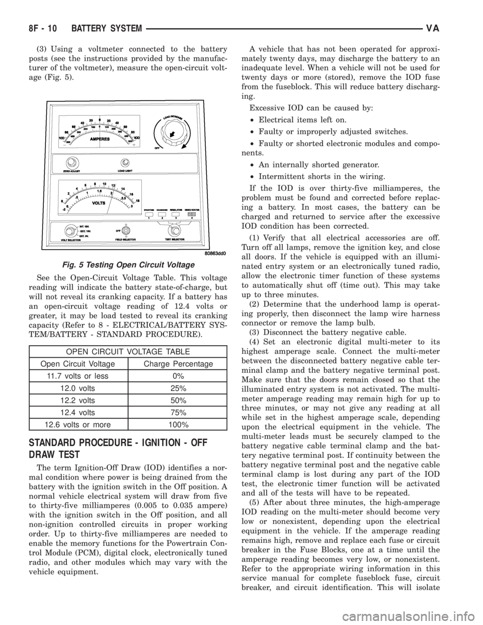
(3) Using a voltmeter connected to the battery
posts (see the instructions provided by the manufac-
turer of the voltmeter), measure the open-circuit volt-
age (Fig. 5).
See the Open-Circuit Voltage Table. This voltage
reading will indicate the battery state-of-charge, but
will not reveal its cranking capacity. If a battery has
an open-circuit voltage reading of 12.4 volts or
greater, it may be load tested to reveal its cranking
capacity (Refer to 8 - ELECTRICAL/BATTERY SYS-
TEM/BATTERY - STANDARD PROCEDURE).
OPEN CIRCUIT VOLTAGE TABLE
Open Circuit Voltage Charge Percentage
11.7 volts or less 0%
12.0 volts 25%
12.2 volts 50%
12.4 volts 75%
12.6 volts or more 100%
STANDARD PROCEDURE - IGNITION - OFF
DRAW TEST
The term Ignition-Off Draw (IOD) identifies a nor-
mal condition where power is being drained from the
battery with the ignition switch in the Off position. A
normal vehicle electrical system will draw from five
to thirty-five milliamperes (0.005 to 0.035 ampere)
with the ignition switch in the Off position, and all
non-ignition controlled circuits in proper working
order. Up to thirty-five milliamperes are needed to
enable the memory functions for the Powertrain Con-
trol Module (PCM), digital clock, electronically tuned
radio, and other modules which may vary with the
vehicle equipment.A vehicle that has not been operated for approxi-
mately twenty days, may discharge the battery to an
inadequate level. When a vehicle will not be used for
twenty days or more (stored), remove the IOD fuse
from the fuseblock. This will reduce battery discharg-
ing.
Excessive IOD can be caused by:
²Electrical items left on.
²Faulty or improperly adjusted switches.
²Faulty or shorted electronic modules and compo-
nents.
²An internally shorted generator.
²Intermittent shorts in the wiring.
If the IOD is over thirty-five milliamperes, the
problem must be found and corrected before replac-
ing a battery. In most cases, the battery can be
charged and returned to service after the excessive
IOD condition has been corrected.
(1) Verify that all electrical accessories are off.
Turn off all lamps, remove the ignition key, and close
all doors. If the vehicle is equipped with an illumi-
nated entry system or an electronically tuned radio,
allow the electronic timer function of these systems
to automatically shut off (time out). This may take
up to three minutes.
(2) Determine that the underhood lamp is operat-
ing properly, then disconnect the lamp wire harness
connector or remove the lamp bulb.
(3) Disconnect the battery negative cable.
(4) Set an electronic digital multi-meter to its
highest amperage scale. Connect the multi-meter
between the disconnected battery negative cable ter-
minal clamp and the battery negative terminal post.
Make sure that the doors remain closed so that the
illuminated entry system is not activated. The multi-
meter amperage reading may remain high for up to
three minutes, or may not give any reading at all
while set in the highest amperage scale, depending
upon the electrical equipment in the vehicle. The
multi-meter leads must be securely clamped to the
battery negative cable terminal clamp and the bat-
tery negative terminal post. If continuity between the
battery negative terminal post and the negative cable
terminal clamp is lost during any part of the IOD
test, the electronic timer function will be activated
and all of the tests will have to be repeated.
(5) After about three minutes, the high-amperage
IOD reading on the multi-meter should become very
low or nonexistent, depending upon the electrical
equipment in the vehicle. If the amperage reading
remains high, remove and replace each fuse or circuit
breaker in the Fuse Blocks, one at a time until the
amperage reading becomes very low, or nonexistent.
Refer to the appropriate wiring information in this
service manual for complete fuseblock fuse, circuit
breaker, and circuit identification. This will isolate
Fig. 5 Testing Open Circuit Voltage
8F - 10 BATTERY SYSTEMVA