Page 416 of 480
415 Practical hints
Batteries
Disconnecting the batteries�
Make sure the gear selector lever is set
to position P.
�
Close the retractable hardtop
(�page 195).
�
Turn off the engine (
�page 60).
�
Turn off all electrical consumers.
�
Remove the SmartKey from the starter
switch.
or
�
Vehicles with KEYLESS-GO*: Open the
driver’s door.
Warning!
G
The brake system requires electrical power
to operate.
A malfunction in the vehicle’s power supply
or electrical system may impair brake sys-
tem operation and switch it into its emer-
gency operation mode. The same applies if
battery is disconnected. To brake, the driver
must then apply significantly greater brake
pedal pressure and depress the pedal much
further to obtain the expected braking ef-
fect. If necessary, apply full pressure to the
brake pedal. Brakes are only applied to the
front wheels. Stopping distance is in-
creased! Adjust your driving style according-
ly. For more information, see
“Electro-hydraulic brake system”
(�page 88).
Warning!
G
With a disconnected battery�
you will no longer be able to turn the
SmartKey in the starter switch and
pressing the KEYLESS-GO* start/stop
button on the gear selector lever will
have no effect
�
the gear selector lever will remain
locked in positionP
!Always disconnect the batteries in the
order described below, even if you only
want to charge the starter battery, for
example. Otherwise the vehicle’s
electronics can be damaged.
��
Page 417 of 480
416 Practical hintsBatteries�
Depress the parking brake pedal.
�
Open the trunk.
�
Read and observe safety instructions
and precautions (
�page 279).
�
Unhook the luggage cover in the trunk.
�
Remove the trunk floor.
The battery for electrical consumers is
located in the right hand area of the
trunk (
�page 383).
�
Use the 10 mm open-end wrench from
the vehicle tool kit to disconnect the
negative lead from negative
terminal4 of the consumer battery
(�page 413).
�
Open the hood (
�page 272).
�
Use the 10 mm open-end wrench from
the vehicle tool kit to disconnect the
negative lead from negative
terminal2 of the starter battery
(�page 413).
�
Remove the covers from the positive
terminals 1 and 3 (
�page 413).
�
Disconnect the positive lead from pos-
itive terminal 3 of the consumer bat-
tery (
�page 413).
�
Disconnect the positive lead from pos-
itive terminal 1 of the starter battery
(�page 413).
Removing the batteries
Removing the consumer battery�
Remove the screws securing the bat-
tery in the trunk.
�
Remove the battery support and
bracket.
�
Pull out the battery ventilation tube
from the battery.
Depending on battery arrangement in
your vehicle model, the ventilation tube
is located either on the left or right side
of the battery.
�
Take out the battery.
��
Page 419 of 480
418 Practical hintsBatteriesReconnecting the batteries�
Turn off all electrical consumers.
�
Install starter battery in the designated
location in the engine compartment.
�
Install consumer battery in the desig-
nated location in the trunk.
�
Attach supports and brackets.
�
Tighten support and bracket screws.
�
Connect positive lead 3 of the con-
sumer battery and positive lead 1 of
the starter battery and fasten covers.
�
Connect negative lead 2 of the starter
battery.
�
Connect negative lead 4 of the con-
sumer battery.
�
Reinstall the trunk floor.
�
Rehook trunk luggage cover into hold-
ers.
!Always connect the batteries in the
order described below. Otherwise the
vehicle’s electronics can be damaged.!Never invert the terminal connections!
iThe following procedures must be car-
ried out following any interruption of
battery power (e.g. due to reconnec-
tion):�
Resynchronize the ESP
®
(
�page 354).
�
Resynchronize side windows
(�page 194).
Page 421 of 480
420 Practical hintsJump startingThe starter battery is located on the right
side of the engine compartment.�
Make sure the two vehicles do not
touch.
�
Turn off all electrical consumers.
�
Apply the parking brake (
�page 59).
�
Shift gear selector lever to positionP.
�
Open the hood (
�page 272).
�
Remove the red cover from positive ter-
minal on both vehicles (
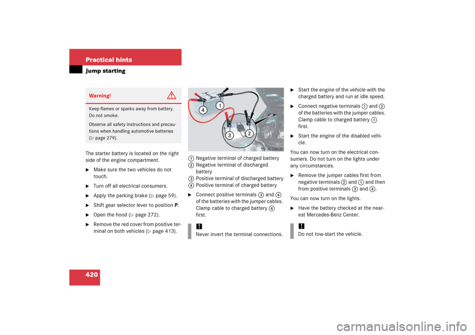
�page 413).1Negative terminal of charged battery
2Negative terminal of discharged
battery
3Positive terminal of discharged battery
4Positive terminal of charged battery
�
Connect positive terminals 3 and 4
of the batteries with the jumper cables.
Clamp cable to charged battery 4
first.
�
Start the engine of the vehicle with the
charged battery and run at idle speed.
�
Connect negative terminals 1 and 2
of the batteries with the jumper cables.
Clamp cable to charged battery 1
first.
�
Start the engine of the disabled vehi-
cle.
You can now turn on the electrical con-
sumers. Do not turn on the lights under
any circumstances.
�
Remove the jumper cables first from
negative terminals 2 and 1 and then
from positive terminals 3 and 4.
You can now turn on the lights.
�
Have the battery checked at the near-
est Mercedes-Benz Center.
Warning!
G
Keep flames or sparks away from battery.
Do not smoke.
Observe all safety instructions and precau-
tions when handling automotive batteries
(�page 279).
!Never invert the terminal connections.
!Do not tow-start the vehicle.
Page 423 of 480
422 Practical hintsTowing the vehicleWarning!
G
If circumstances require towing the vehicle
with all wheels on the ground, always tow
with a tow bar if:�
the engine will not run
�
there is a malfunction in the
electro-hydraulic brake system
�
there is a malfunction in the power sup-
ply or in the vehicle’s electrical system
as that will be necessary to adequately con-
trol the towed vehicle.
Prior to towing the vehicle with all wheels on
the ground, make certain that the SmartKey
is in starter switch position2.
If the SmartKey is left in starter switch
position0 for an extended period of time, it
can no longer be turned in the switch. In this
case, the steering is locked. To unlock, re-
move SmartKey from starter switch and re-
insert.
iTo signal turns while being towed with
the hazard warning flasher in use, turn
SmartKey in starter switch to
position2 and activate the combina-
tion switch for the left or right turn sig-
nal in the usual manner – only the
selected turn signal will operate.
Upon canceling the turn signal, the haz-
ard warning flasher will operate again.
Warning!
G
The brake system requires electrical power
to operate.
A malfunction in the vehicle’s power supply
or electrical system may impair brake sys-
tem operation and switch it into its emer-
gency operation mode. To brake, the driver
must then apply significantly greater brake
pedal pressure and depress the pedal much
further to obtain the expected braking ef-
fect. If necessary, apply full pressure to the
brake pedal. Brakes are only applied to the
front wheels. Stopping distance is in-
creased! Adapt your driving style according-
ly. For more information, see
“Electro-hydraulic brake system”
(�page 88).
With the engine not running, there is no
power assistance for the brake and steering
systems. In this case, it is important to keep
in mind that a considerably higher degree of
effort is necessary to brake and steer the ve-
hicle. Adapt your driving accordingly.
Page 424 of 480
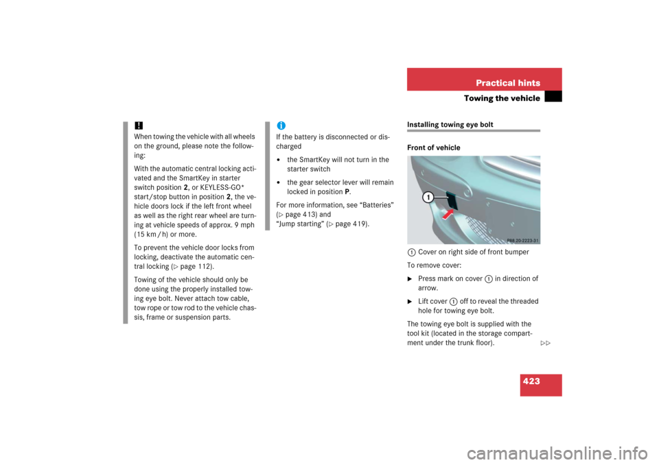
423 Practical hints
Towing the vehicle
Installing towing eye bolt
Front of vehicle
1Cover on right side of front bumper
To remove cover:�
Press mark on cover 1 in direction of
arrow.
�
Lift cover1off to reveal the threaded
hole for towing eye bolt.
The towing eye bolt is supplied with the
tool kit (located in the storage compart-
ment under the trunk floor).
!When towing the vehicle with all wheels
on the ground, please note the follow-
ing:
With the automatic central locking acti-
vated and the SmartKey in starter
switch position2, or KEYLESS-GO*
start/stop button in position2, the ve-
hicle doors lock if the left front wheel
as well as the right rear wheel are turn-
ing at vehicle speeds of approx. 9 mph
(15 km / h) or more.
To prevent the vehicle door locks from
locking, deactivate the automatic cen-
tral locking (
�page 112).
Towing of the vehicle should only be
done using the properly installed tow-
ing eye bolt. Never attach tow cable,
tow rope or tow rod to the vehicle chas-
sis, frame or suspension parts.
iIf the battery is disconnected or dis-
charged�
the SmartKey will not turn in the
starter switch
�
the gear selector lever will remain
locked in positionP.
For more information, see “Batteries”
(
�page 413) and
“Jump starting” (
�page 419).
��
Page 426 of 480

425 Practical hintsFuses
�Fuses
Fuses are designed to protect the electri-
cal circuits in your vehicle from a short cir-
cuit. If a fuse is blown, the components
and systems secured by that fuse will stop
operating.
The following aids are available to help you
replace fuses. They are located in the trunk
with the vehicle tool kit (
�page 383).
�
Fuse chart
The fuse chart explains the fuse alloca-
tion and fuse amperages.
�
Spare fuses
�
Fuse extractor
Main fuse box
The main fuse box is located in the engine
compartment on the driver’s side in front
of the bulkhead (wall separating the engine
and passenger compartment).
1Main fuse box cover
2Locking
3Unlocking
Warning!
G
Only use fuses approved by Mercedes-Benz
with the specified amperage for the system
in question. Using other fuses may cause an
overload leading to a fire, and/or cause
damage to electrical components and/or
systems.!Never attempt to repair or bridge a
blown fuse. Have the cause determined
and remedied by an authorized
Mercedes-Benz Center.
Page 427 of 480
426 Practical hintsFusesOpening�
Open the hood (
�page 272).
�
Move slide to position 3 and lift
cover1.
Closing
�
Hook cover 1 onto tabs and close it.
�
Move slide to position 2.
Emergency engine shut-down
If the engine cannot be turned off as de-
scribed, you may use the following backup
procedure.�
Open the main fuse box (
�page 425).
�
Pull out the two fuses labeled “ENGINE
EMERGENCY STOP”.
!The fuse box cover must be properly
positioned with the slide at the ‹
symbol to prevent moisture or dirt from
entering the fuse box and possibly im-
pairing fuse operation.