Page 318 of 561

317 Controls in detail
Useful features
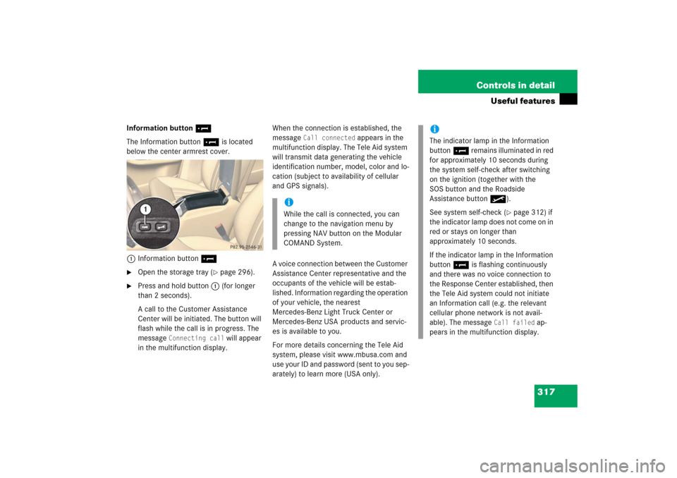
Information button¡
The Information button¡ is located
below the center armrest cover.
1Information button¡�
Open the storage tray (
�page 296).
�
Press and hold button1 (for longer
than 2 seconds).
A call to the Customer Assistance
Center will be initiated. The button will
flash while the call is in progress. The
message
Connecting call
will appear
in the multifunction display.When the connection is established, the
message
Call connected
appears in the
multifunction display. The Tele Aid system
will transmit data generating the vehicle
identification number, model, color and lo-
cation (subject to availability of cellular
and GPS signals).
A voice connection between the Customer
Assistance Center representative and the
occupants of the vehicle will be estab-
lished. Information regarding the operation
of your vehicle, the nearest
Mercedes-Benz Light Truck Center or
Mercedes-Benz USA products and servic-
es is available to you.
For more details concerning the Tele Aid
system, please visit www.mbusa.com and
use your ID and password (sent to you sep-
arately) to learn more (USA only).
iWhile the call is connected, you can
change to the navigation menu by
pressing NAV button on the Modular
COMAND System.
iThe indicator lamp in the Information
button¡ remains illuminated in red
for approximately 10 seconds during
the system self-check after switching
on the ignition (together with the
SOS button and the Roadside
Assistance button•).
See system self-check (
�page 312) if
the indicator lamp does not come on in
red or stays on longer than
approximately 10 seconds.
If the indicator lamp in the Information
button¡ is flashing continuously
and there was no voice connection to
the Response Center established, then
the Tele Aid system could not initiate
an Information call (e.g. the relevant
cellular phone network is not avail-
able). The message
Call failed
ap-
pears in the multifunction display.
Page 405 of 561

404 Practical hintsWhat to do if …Lamps in instrument clusterGeneral information:
If any of the following lamps in the instru-
ment cluster fails to come on during thebulb self-check when switching on the
ignition, have the respective bulb checked
and replaced if necessary.Problem
Possible cause/consequence
Suggested solution
-
The yellow ABS indicator lamp
comes on while the engine is
running.
ABS has detected a malfunction and has
switched off. The BAS, ESP
®, and 4-ETS are
also switched off (see messages in multifunc-
tion display).
The brake system is still functioning normally
but without the ABS available.
If the ABS control unit is malfunctioning,
other systems such as the navigation
system* or the automatic transmission may
also be malfunctioning.
�
Continue driving with added caution.
Wheels may lock during hard braking,
reducing steering capability.
�
Read and observe messages in the
multifunction display (
�page 416).
�
Have the system checked at an
authorized Mercedes-Benz Light
Truck Center as soon as possible.
Failure to follow these instructions
increases the risk of an accident.
The charging voltage has fallen below
10 volts. The ABS has switched off.
The battery might not be charged sufficiently.
�
Switch off electrical consumers that
are currently not needed, e.g. seat
heating*.
�
If necessary, have the generator
(alternator) and battery checked.
When the voltage is above this value
again, the ABS is operational again.
Page 495 of 561

494 Practical hintsBattery�
Carry out step 8 to reconnect the bat-
tery (
�page 493).
�
Carry out steps 6 to 1 in reverse order
to complete reinstall the battery,
(�page 492) to (
�page 490).
Step 11 (Reconnecting)
�
If the battery has been removed, carry
out step 9 (
�page 493) first and then
step 7 (
�page 493), both in reverse
order, before starting the connecting
procedure.
�
Open the driver’s door.
�
Make sure the SmartKey is removed
from the starter switch.
Vehicles with KEYLESS-GO*:�
Make sure the vehicle’s on-board
electronics have status 0.
With the driver’s door opened, the
vehicle’s on-board electronics have
status 0, same as SmartKey re-
moved from the starter switch
(�page 39).
�
Connect the positive lead to the posi-
tive terminal and fasten it’s cover
(�page 493).
�
Connect the negative lead to the nega-
tive terminal (
�page 493).
!Never invert the terminal connections!
iThe following procedures must be car-
ried out following any interruption of
battery power (e.g. due to disconnec-
tion):�
Set the clock (
�page 180).
Vehicles with Modular COMAND
system with navigation module*:
Time and date are set automatical-
ly.
�
Synchronize the door windows
(�page 251).
�
Synchronize the power tilt/sliding
sunroof* (
�page 258).
�
Synchronize the power tilt/sliding
panel* (
�page 262).
�
Synchronize the power folding
exterior rear view mirrors*
(�page 211).
��
Page 532 of 561

531 Technical terms
GPS
(G
lobal P
ositioning S
ystem)
Satellite-based system for relaying
geographic location information to and
from vehicles equipped with special re-
ceivers. Employs CD or DVD digital
maps for navigation.
GVW
(G
ross V
ehicle W
eight)
(
�page 386)
GVWR
(Gross V
ehicle W
eight R
ating)
(
�page 386)
Instrument cluster
The displays and indicator/warning
lamps in the driver’s field of vision, in-
cluding the tachometer, speedometer,
engine temperature and fuel gauge.Kickdown
Depressing the accelerator past the
point of resistance shifts the transmis-
sion down to the lowest possible gear.
This very quickly accelerates the vehi-
cle and should not be used for normal
acceleration needs.
Kilopascal (kPa)
(
�page 386)
Line of fall
The direct line that an object moves
downhill when influenced by the force
of gravity alone.
Locking knob
Knob on the door which indicates
whether the door is locked or un-
locked. Pushing the locking knob down
on an individual door from inside will
lock that door.Maintenance System (U.S. vehicles)
Maintenance service indicator in the
multifunction display that informs the
driver when the next vehicle mainte-
nance service is due. The Maintenance
system tracks distance driven and the
time elapsed since the last mainte-
nance service, calculates other mainte-
nance service work required, and calls
for the next service accordingly.
Maximum load rating
(
�page 387)
Maximum loaded vehicle weight
(�page 387)
Maximum tire inflation pressure
(�page 387)
Modular COMAND System
Information and operating center for
vehicle sound and communications
systems, including the radio and the ra-
dio and navigation system, as well as
for other optional equipment (CD
changer, telephone, etc.).
Page 548 of 561

547 Index
Mirrors
Adjusting 47
Automatic antiglare for rear view
mirror 209
Exterior rear view mirror 48
Storing exterior rear view mirror park-
ing position 146
Modular Control System 531
MON 343
MON (Motor Octane Number) 532
Mph or km/h in speedometer 178
Multicontour seat* 136
Multifunction display 532
Selecting language 178
Standard display 165
Multifunction display messages
ABS 418
Batteries 430
Brake fluid 432
Brake pads 430
Coolant 436
Coolant level 433
Doors 436
EBP (Electronic Brake
Proportioning) 431
Engine oil 437, 438Fuel cap 439
Hood 439
Lamps 444
Lamps, exterior 442
Oil 437–438
Parking brake 431
SmartKey 441
SmartKey with KEYLESS-GO* 440
Tele Aid* 450, 451
Telephone* 451
Washer fluid 451
Multifunction steering wheel 28, 532
N
Navigation system 172
Night security illumination 150
Normal occupant weight 387, 532
O
Occupant Classification System 85
Self-test 90
Occupant distribution 387Occupant safety 70
Children and air bags 72
Children in the vehicle 82
Fastening the seat belt 50
Infant and child restraint systems 82
LATCH child seat mounts 92
Seat belts 50, 74
Oil
Adding 349
Consumption 346
Dipstick 346
Filler neck 349
Viscosity 530
One-touch gearshifting
Canceling gear range limit 207
Opening
Doors from the inside 121
Fuel filler flap 342
Fuel filler flap manually 461
Glove box 294
Hood 345