Page 179 of 417

178 Controls in detail
Power tilt/sliding sunroof
Opening and closing the power
tilt/sliding sunroof
The tilt/sliding sunroof is opened and
closed electrically. The switch for the
tilt/sliding sunroof is on the overhead con-
trol panel.
Sunroof switch
1Push up to raise sunroof at rear
2Pull down to lower sunroof at rear
3Push forward to slide sunroof closed
4Push back to slide sunroof open
Warning!G
When closing the tilt/sliding sunroof, make
sure there is no danger of anyone being
harmed by the closing procedure.
The opening procedure of the tilt/sliding
sunroof can be immediately halted by re-
leasing the switch or, if the switch was
moved past the resistance point and re-
leased, by moving the switch in any direc-
tion.
The closing procedure of the tilt/sliding sun-
roof can be immediately halted by releasing
the switch.
The closing procedure can be immediately
reversed by moving the switch in
direction1or4.
In a vehicle rollover, occupants not wearing
their seat belts or not wearing them properly
may be thrown out of the opening. Such an
opening also presents a potential for injury
for occupants wearing their seat belts prop-
erly as entire body parts or portions of them
may protrude from the passenger compart-
ment.
When leaving the vehicle, always remove the
SmartKey from the starter switch, take it
with you, and lock the vehicle. Do not leave
children unattended in the vehicle, or with
access to an unlocked vehicle. Unsuper-
vised use of vehicle equipment can cause an
accident and/or serious personal injury.
Page 180 of 417
.Opening and closing the tilt/sliding
sunroof
�To open, close, raise, or lower the
tilt/sliding sunroof, move the")
179 Controls in detail
Power tilt/sliding sunroof
�Switch on the ignition (�page 35).Opening and closing the tilt/sliding
sunroof
�To open, close, raise, or lower the
tilt/sliding sunroof, move the sunroof
switch to resistance point in the re-
quired direction of arrows1to4.
Release the sunroof switch when the
tilt/sliding sunroof has reached the de-
sired position.
Fully opening (Express-open) the
tilt/sliding sunroof
�To open the tilt/sliding sunroof, move
the sunroof switch past the resistance
point in direction of arrow4 and
release.
The tilt/sliding sunroof opens
completely.
Stopping the tilt/sliding sunroof during
Express-operation
�Move the sunroof switch in any
direction.Opening and closing the tilt/sliding
sunroof with the SmartKey
The power windows (
�page 175) will also
be opened or closed when you operate the
tilt/sliding sunroof with the SmartKey.
!
To avoid damaging the seals, do not
transport any objects with sharp edges
which can stick out of the tilt/sliding
sunroof.
Do not open the tilt/sliding sunroof if
there is snow or ice on the roof, as this
could result in malfunctions.
The tilt/sliding sunroof can be opened
or closed manually should an electrical
malfunction occur (
�page 330).
i
You can also open or close the
tilt/sliding sunroof using the SmartKey
(summer opening/convenience closing
feature) (
�page 179).
Warning!G
Never operate the windows or tilt/sliding
sunroof if there is the possibility of anyone
being harmed by the opening or closing pro-
cedure.
In case the procedure causes potential dan-
ger, the procedure can be immediately halt-
ed by releasing the button on the SmartKey.
To reverse direction of movement,
pressŒ for opening or ‹ for closing.
Page 181 of 417

�P")
180 Controls in detail
Power tilt/sliding sunroof
�Aim transmitter eye at the driver’s door
handle.
The SmartKey must be in close proxim-
ity to the door handle.
Opening (Summer opening feature)
�Press and hold buttonŒ after un-
locking the vehicle.
The windows and tilt/sliding sunroof
begin to open after approximately
1 second.
�Release transmit button to interrupt
procedure.Closing (Convenience closing feature)
�Press and hold button‹ after lock-
ing the vehicle.
The windows and tilt/sliding sunroof
begin to close after approximately
1 second.
�Release transmit button to interrupt
procedure.
Make sure all side windows and the
tilt/sliding sunroof are properly closed be-
fore leaving the vehicle.
Warning!G
When closing the windows and tilt/sliding
sunroof, make sure that there is no danger
of anyone being harmed by the closing pro-
cedure.
If potential danger exists, proceed as fol-
lows:
�Release button‹ to stop the closing
procedure. To open, press and hold
buttonŒ. To continue the closing
procedure after making sure that there
is no danger of anyone being harmed by
the closing procedure, press and hold
button ‹.
Page 195 of 417

194 Controls in detail
Useful features
Storage compartments
Glove box
1Unlocked position
2Locked position
3HandleOpening the glove box
�Pull handle to open.
The glove box is illuminated with SmartKey
in starter switch position1 or2 when
opening the lid.
Closing the glove box
�Push lid up to close.
Warning!G
To help avoid personal injury during a colli-
sion or sudden maneuver, exercise care
when storing objects in the vehicle. Put lug-
gage or cargo in the cargo compartment if
possible. Do not pile luggage or cargo higher
than the seat backs.
Luggage nets cannot secure hard or heavy
objects.
Warning!G
Do not load items on the roof. It may cause
instability during some maneuvers which
could result in an accident.
Warning!G
Keep compartment lids closed. This will help
to prevent stored objects from being thrown
about and injuring vehicle occupants during
an accident and sudden maneuvers.
i
The glove box can be locked and un-
locked with the mechanical key.
i
The glove box lid contains two cup
holders.
Page 201 of 417
200 Controls in detail
Useful features
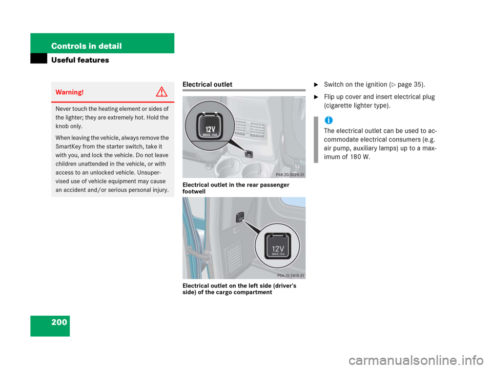
Electrical outlet
Electrical outlet in the rear passenger
footwell
Electrical outlet on the left side (driver’s
side) of the cargo compartment
�Switch on the ignition (�page 35).
�Flip up cover and insert electrical plug
(cigarette lighter type).Warning!G
Never touch the heating element or sides of
the lighter; they are extremely hot. Hold the
knob only.
When leaving the vehicle, always remove the
SmartKey from the starter switch, take it
with you, and lock the vehicle. Do not leave
children unattended in the vehicle, or with
access to an unlocked vehicle. Unsuper-
vised use of vehicle equipment may cause
an accident and/or serious personal injury.
N
N
i
The electrical outlet can be used to ac-
commodate electrical consumers (e.g.
air pump, auxiliary lamps) up to a max-
imum of 180 W.
Page 210 of 417
,
and the reserve key is not handy:
�Contact the Mercede")
209 Controls in detail
Useful features
Remote door unlock
In case you have locked your vehicle unin-
tentionally (e.g. SmartKey inside vehicle),
and the reserve key is not handy:
�Contact the Mercedes-Benz Response
Center at 1-800-756-9018 (in the USA)
or 1-888-923-8367 (in Canada).
You will be asked to provide your pass-
word which you provided when you
completed the subscriber agreement.
�Then return to your vehicle and press
the tailgate lock for minimum of
20 seconds until the SOS button is
flashing.
The message
EMERGENCY CALL –
CALL CONNECTED
appears in the multi-
function display.
As an alternative, you may unlock the vehi-
cle via Internet using the ID and password
sent to you shortly after the completion of
your acquaintance call.
!
If the indicator lamp continues to flash
or the system does not reset, contact
the Response Center at
1-800-756-9018 (in the USA) or
1-888-923-8367 (in Canada), or
Mercedes-Benz Customer Assistance
at 1-800-FOR-MERCedes
(1-800-367-6372) in the USA or
Customer Service at 1-800-387-0100
in Canada.
i
When a Tele Aid call has been initiated,
the COMAND system audio is muted
and the selected mode (radio or CD)
pauses. The optional cellular phone (if
installed) switches off. If you must use
this phone, the vehicle must be parked.
Disconnect the coiled cord and place
the call. The navigation system (if en-
gaged) will continue to run. The display
in the instrument cluster is available for
use and spoken commands are only
available by pressing the RPT button on
the COMAND unit. A pop-up window
will appear in the COMAND display to
indicate that a Tele Aid call is in
progress.
Page 217 of 417
216 Controls in detail
Useful features
Switching on
�Switch on the ignition (�page 35).
All lamps in the instrument cluster
come on.
�Turn switch at the tip of lever in direc-
tion of arrow1.
The steering wheel is heated. Indicator
lamp3 comes on.Switching off
�Turn switch at the tip of lever in direc-
tion of arrow2.
The steering wheel heater is turned off.
Indicator lamp3 goes out.
i
The steering wheel heating is tempo-
rarily suspended while indicator
lamp3 remains on when
�the temperature of the vehicle inte-
rior is above 86°F (30°C)
�the temperature of the steering
wheel is above 95°F (35°C)
When these conditions do not apply
anymore, steering wheel heating con-
tinues.
i
Indicator lamp3 flashes or switches
off in case of
�power surge or undervoltage
�steering wheel heating malfunction
i
The steering wheel heating switches off
automatically when you remove the
SmartKey from the starter switch.
Page 224 of 417
 are required by
law. These indicators are located in six
places on the tread circumference and be-
come visible at a tread depth o")
223 Operation
Driving instructions
Tires
Treadwear indicators (TWI) are required by
law. These indicators are located in six
places on the tread circumference and be-
come visible at a tread depth of approxi-
mately
1/16in (1.6 mm), at which point
the tire is considered worn and should be
replaced.The treadwear indicator appears as a solid
band across the tread.
Specified tire inflation pressures must be
maintained. This applies particularly if the
tires are subject to high loads (e.g. high
speeds, heavy loads, high ambient temper-
atures).
�Turn the SmartKey in the starter switch
to position0 and remove the SmartKey
from the starter switch.
�Take the SmartKey and lock vehicle
when leaving.
!
Set the parking brake whenever park-
ing or leaving the vehicle. In addition,
move gear selector lever to positionP.
When parking on hills, turn front wheel
towards the road curb.
Warning!G
If you feel a sudden significant vibration or
ride disturbance, or you suspect that possi-
ble damage to your vehicle has occurred,
you should turn on the hazard warning flash-
ers, carefully slow down, and drive with cau-
tion to an area which is a safe distance from
the road.
Inspect the tires and the vehicle underbody
for possible damage. If the vehicle or tires
appear unsafe, have it towed to the nearest
Mercedes-Benz Light Truck Center or tire
dealer for repairs.
Warning!G
Although the applicable federal motor vehi-
cle safety laws consider a tire to be worn
when the treadwear indicators (TWI) be-
come visible at approximately
1/16in
(1.6 mm), we recommend that you do not al-
low your tires to wear down to that level. As
tread depth approaches
1/8in (3.0 mm),
the adhesion properties on a wet road are
sharply reduced.
Depending upon the weather and/or road
surface (conditions), the tire traction varies
widely.