Page 227 of 322
67
In case of an emergency
ELECTRICAL CIRCUIT PROTECTION Fuses A vehicle’s electrical system is pro-
tected from electrical overload dam-
age by fuses.
This vehicle has two fuse panels,
one located in the driver's side knee
bolster, the other in the engine com-
partment near the battery.If any of your vehicle’s lights, acces-
sories, or controls do not work, check
the appropriate circuit fuse. If a fuse
has blown, the element inside the
fuse will be melted.
If the electrical system does not
work, first check the driver’s side
fuse panel.
Always replace a blown fuse with
one of the same rating.
If the replacement fuse blows, this
indicates an electrical problem. Avoid
using the system involved and imme-
diately consult an Authorized Kia
Dealer.
Two kinds of fuses are used: stan-
dard for lower amperage rating andmain for higher amperage ratings.
1
2
3
4
5
6
7
8
910
MMSA6003
Standard
Main fuse
Normal Normal Blown
Blown
Page 228 of 322
In case of an emergency86Fuse replacement
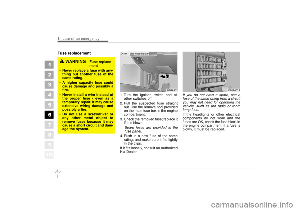
1. Turn the ignition switch and allother switches off.
2. Pull the suspected fuse straight out. Use the removal tool provided
on the main fuse box in the engine
compartment.
3. Check the removed fuse; replace it if it is blown.
Spare fuses are provided in thefuse panel.
4. Push in a new fuse of the same rating, and make sure it fits tightly
in the clips.
If it fits loosely, consult an Authorized
Kia Dealer.
If you do not have a spare, use a fuse of the same rating from a circuityou may not need for operating thevehicle, such as the radio or roomlamp fuse.If the headlights or other electrical
components do not work and the
fuses are OK, check the fuse block in
the engine compartment. If a fuse is
blown, it must be replaced.
1
2
3
4
5
6
7
8
910
1GHA402
1GHA403A
WARNING
- Fuse replace-
ment
Never replace a fuse with any- thing but another fuse of the
same rating.
A higher capacity fuse could cause damage and possibly a
fire.
Never install a wire instead of the proper fuse - even as a
temporary repair. It may cause
extensive wiring damage and
possibly a fire.
Do not use a screwdriver or any other metal object to
remove fuses because it may
cause a short circuit and dam-
age the system.
Driver - side knee bolster
Page 230 of 322
In case of an emergency10
6
1
2
3
4
5
6
7
8
910
Relay panel description* For Canadian model
ETS
H/LAMP
(LO-RH)
DRL*
(TAIL)
DRL*
(RESISTOR)
H/LP
WASHER*
Passenger-side panel
Engine compartment
2GHN601/2GHN602
Relay name Relay description
Passenger - side panel
BLOWER (HI) Air conditioner blower relay (high)
Engine compartment
H/LP WASHER* Head lamp washer relay
ETS Electronic throttle system relay
DRL (RESISTOR)* Daytime running light (Resistor) relay
DRL (TAIL)* Daytime running light (Taillight) relay
H/LAMP (LO-RH) Headlight relay (low beam-right)
Page 231 of 322
611
In case of an emergency
1
2
3
4
5
6
7
8
910
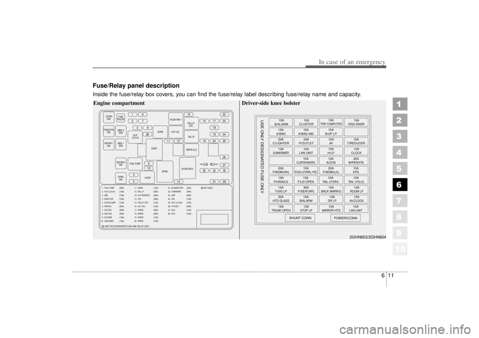
Fuse/Relay panel descriptionInside the fuse/relay box covers, you can find the fuse/relay label describing fuse/relay name and capacity.
C/FAN20A
FUSE
PULLER
P/SEAT(FR) 30A
H/
LP (LO-LH) HORN
START
IGN SW-2 30A
R/FAN 30A R/FAN
A/CON FAN-2WIPER (LO)
TAIL
LP
H/LP (HI)
A/CON FAN-1
FOG
LP(FR)
FUEL PUMP A/CON
16
2738
11 12 16 20
15
14
17
1822
23
19 25 24
27
21
13
9
10
4
5 28
26
IGN SW-1
30A
ABS 230A
ABS 1 30A
1. FUEL PUMP
2. H/LP (LO-LH)
3. ABS
4. INJECTOR
5. A/CON COMP
6. ATM RLY
7. ECU RLY
8. IGN COIL
9. O2 SNSR
10. ENG SNSR
(20A)
(15A)
(10A)
(10A)
(10A)
(20A)
(20A)
(20A)
(15A)
(15A)
11. HORN
12. TAIL LP
13. H/LP WASHER
14. ETS
15. FOG LP (FR)
16. H/LP (HI)
17. SPARE
18. SPARE
19. SPARE
20. SPARE
(15A)
(20A)
(20A)
(20A)
(15A)
(15A)
(30A)
(20A)
(15A)
(10A)
21. BLOWER MTR
22. S/WARMER
23. AMP
24. DRL
25. H/LP (LO-RH)
26. P/FUSE-1
27. ECU
28. ECS NOT USED
(30A)
(30A)
(20A)
(15A)
(15A)
(30A)
(10A)
(15A)
USE THE DESIGNATED FUSE AND RELAY ONLT.
Engine compartment
10A
B/ALARM
15A
A/BAG
20A
C/LIGHTER
10AS/WARMER20AP/WDW(RH)15AP/HANDLE15AT/SIG LP30AHTD GLASS15A
TRUNK OPEN
SHUNT CONN
USE ONLY DESIGNATED FUSE ONLY
POWER/CONN
15ASTOP LP
10A
MIRROR HTD
10ALAN UNIT
10AB/ALARM
10ADR LP
15AAV.CLOCK
30AP/SEAT(RR)
10A
BACK WARN'G
10AROOM LP
15AF/LID OPEN
10ATAIL LP(RH)
10ATAIL LP(LH)
15A
FOG LP(RR), PIC
20AP/WDW(LH)
10AEPS
10A
CURTAIN(RR)
10AA/CON
20AWIPER(FR)
10A
LAN UNIT 10A
H/LP 10A
CLOCK
20A
P/OUTLET 10A
T/REDUCER
10A
AV
10A
A/BAG IND 10A
B/UP LP
10A
CLUSTER 10A
ENG SNSR
10A
TRIP COMPUTER
2GHN603/2GHN604
Driver-side knee bolster
Page 232 of 322
In case of an emergency12
6
1
2
3
4
5
6
7
8
910
* For Canadian model
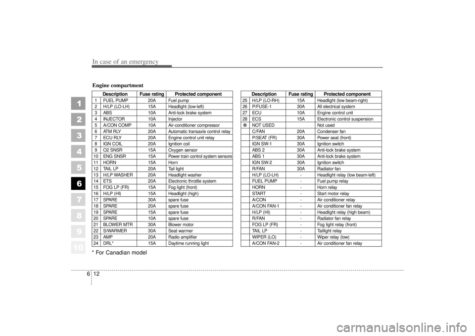
Description Fuse rating Protected component
1 FUEL PUMP 20A Fuel pump
2 H/LP (LO-LH) 15A Headlight (low-left)
3 ABS 10A Anti-lock brake system
4 INJECTOR 10A Injector
5 A/CON COMP 10A Air-conditioner compressor
6 ATM RLY 20A Automatic transaxle control relay
7 ECU RLY 20A Engine control unit relay
8 IGN COIL 20A Ignition coil
9 O2 SNSR 15A Oxygen sensor
10 ENG SNSR 15A
Power train control system sensors
11 HORN 15A Horn
12 TAIL LP 20A Tail light
13 H/LP WASHER 20A Headlight washer
14 ETS 20A Electronic throttle system
15 FOG LP (FR) 15A Fog light (front)
16 H/LP (HI) 15A Headlight (high)
17 SPARE 30A spare fuse
18 SPARE 20A spare fuse
19 SPARE 15A spare fuse
20 SPARE 10A spare fuse
21 BLOWER MTR 30A Blower motor
22 S/WARMER 30A Seat warmer
23 AMP 20A Radio amplifier
24 DRL* 15A Daytime running light
Description Fuse rating Protected component
25 H/LP (LO-RH) 15A Headlight (low beam-right)
26 P/FUSE-1 30A All electrical system
27 ECU 10A Engine control unit
28 ECS 15A Electronic control suspension
� NOT USED Not used
C/FAN 20A Condenser fan
P/SEAT (FR) 30A Power seat (front)
IGN SW-1 30A Ignition switch
ABS 2 30A Anti-lock brake system
ABS 1 30A Anti-lock brake system
IGN SW-2 30A Ignition switch
R/FAN 30A Radiator fan
H/LP (LO-LH) - Headlight relay (low beam-left)
FUEL PUMP - Fuel pump relay
HORN - Horn relay
START - Start motor relay
A/CON - Air conditioner relay
A/CON FAN-1 - Air conditioner fan relay
H/LP (HI) - Headlight relay (high beam)
R/FAN - Radiator fan relay
FOG LP (FR) - Fog light relay (front)
TAIL LP - Taillight relay
WIPER (LO) - Wiper relay (low)
A/CON FAN-2 - Air conditioner fan relay
Engine compartment
Page 233 of 322
613
In case of an emergency
1
2
3
4
5
6
7
8
910
Driver-side knee bolster
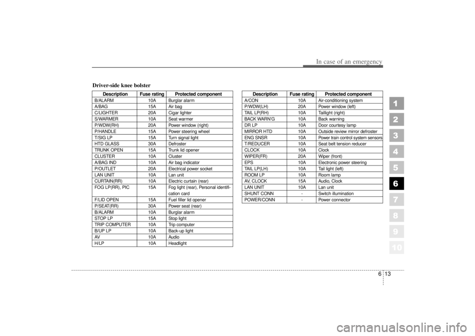
Description Fuse rating Protected component
B/ALARM10A Burglar alarm
A/BAG 15A Air bag
C/LIGHTER 20A Cigar lighter
S/WARMER 10A Seat warmer
P/WDW(RH) 20A Power window (right)
P/HANDLE 15A Power steering wheel
T/SIG LP 15A Turn signal light
HTD GLASS 30A Defroster
TRUNK OPEN 15A Trunk lid opener
CLUSTER 10A Cluster
A/BAG IND 10A Air bag indicator
P/OUTLET 20A Electrical power socket
LAN UNIT 10A Lan unit
CURTAIN(RR) 10A Electric curtain (rear)
FOG LP(RR), PIC 15A Fog light (rear), Personal identifi- cation card
F/LID OPEN 15A Fuel filler lid opener
P/SEAT(RR) 30A Power seat (rear)
B/ALARM 10A Burglar alarm
STOP LP 15A Stop light
TRIP COMPUTER 10A Trip computer
B/UP LP 10A Back-up light
AV 10A Audio
H/LP 10A Headlight
Description Fuse rating Protected component
A/CON10A Air-conditioning system
P/WDW(LH) 20A Power window (left)
TAIL LP(RH) 10A Taillight (right)
BACK WARN’ G10A Back warning
DR LP 10A Door courtesy lamp
MIRROR HTD 10A Outside review mirror defroster
ENG SNSR 10A
Power train control system sensors
T/REDUCER10A Seat belt tension reducer
CLOCK 10A Clock
WIPER(FR) 20A Wiper (front)
EPS 10A Electronic power steering
TAIL LP(LH) 10A Tail light (left)
ROOM LP 10A Room lamp
AV, CLOCK 15A Audio, Clock
LAN UNIT 10A Lan unit
SHUNT CONN - Switch illumination
POWER/CONN - Power connector
Page 234 of 322
In case of an emergency14
6
1
2
3
4
5
6
7
8
910
Power connectorYour vehicle is equipped with a
power connector to prevent battery
discharge if your vehicle is parked
without being operated for prolonged
periods. Use the following proce-
dures before parking the vehicle for
prolonged period. 1. Turn off the engine.
2. Turn off the headlights and tail
lights.
3. Open the driver-side knee bolster cover and pull up the
“POWER/CONN”.
✽ ✽NOTICE• If the power connector is pulled up
from the fuse panel, the warning
chime, AV system, clock and
intetrior lamps, etc., will not oper-
ate. Some items must be reset after
replacement. (Refer to “Items to
be reset···.” on page 7-36)
• Even though the power connector is pulled up, the battery can still
be discharged by operation of the
headlights or other electrical
devices.
1GHA403Power
connector
Page 255 of 322
711
Maintenance
OWNER MAINTENANCE Owner maintenance schedule The following lists are vehicle checks
and inspections that should be per-
formed by the owner or qualified
service technician at the frequencies
indicated to help ensure safe,
dependable operation of your vehi-
cle.
Any adverse conditions should be
brought to the attention of your deal-
er or qualified service technician or
service advice as soon as possible.
These Owner Maintenance Checks
are generally not covered by war-
ranties and you may be charged for
labor, parts and lubricants used.
When you stop for fuel: Check the engine oil level.
Check coolant level in coolantreservoir.
Check the windshield washer fluid level.
Look for low or under-inflated tires.
While operating your vehicle: Note any changes in the sound of the exhaust or any smell of
exhaust fumes in the vehicle.
Check for vibrations in the steering wheel. Notice any increased steer-
ing effort or looseness in the steer-
ing wheel, or change in its straight-
ahead position.
Notice if your vehicle constantly turns slightly or “pulls” to one side
when traveling on smooth, level
road.
When stopping, listen and check for strange sounds, pulling to one
side, increased brake pedal travel
or “hard-to-push” brake pedal.
If any slipping or changes in the operation of your transaxle occurs,
check the transaxle fluid level.
Check automatic transaxle P (Park) function.
Check parking brake.
Check for fluid leaks under your vehicle (water dripping from the air
conditioning system after use is
normal).
1
2
3
4
5
6
7
8
910
WARNING
Be careful when checking your
engine coolant level when the
engine is hot. Scalding hot
coolant and steam may blow out
under pressure. This could
cause serious injury.