Page 8 of 322
10
Your vehicle at a glance22
1
2
3
4
5
6
7
8
9
EXTERIOR OVERVIEW
1. Headlight (high beam)
2. Headlights (low beam)
3. Turn signal light
4. Side mark light
5. Engine hood
6. Inside rearview mirror
7. Seat
8. Steering wheel
9. Door
10. Outside rearview mirror
2GHN0001
Page 9 of 322
10
23
1
2
3
4
5
6
7
8
9
Your vehicle at a glance
1. Rear door child safety lock
2. Fuel filler lid
3. Rear window
4. Trunk release lever and key lock
5. Spare tire
6. Outside rearview mirror
7. Tail lights
8. High mounted stop light
9. Door handle (driver)
10. Door handle (passenger)
11. Emergency trunk release lever
2GHN0002
Page 11 of 322
10
25
1
2
3
4
5
6
7
8
9
Your vehicle at a glance
INSTRUMENT PANEL OVERVIEW
1. Driver’s Air Bag
2. Light control / Turn signals
3. Instrument cluster
4. Wiper/Washer
5. Ignition switch
6. Seat warmer
7. Traction control system (if equipped)/ Electronic stability program (if equipped)
8. Hazard
9. Rear climate control selection button
10. Climate control system
11. Shift lever
12. Passenger’s airbag
13. Glove box
14. Trunk lid control button
15. Audio controls (if equipped)
16. Auto cruise controls (if equipped)
17. Coin holders
18. Multi-Function Display (if equipped)
2GHN0004
RES
ACCELCOAST
SETCRUISE
ON/OFFCANCEL
TCS
Page 12 of 322
101
2
3
4
5
6
7
8
9
Keys / 3-2
Remote keyless entry / 3-4
Immobilizer system / 3-7
Door locks / 3-9
Window / 3-14
Seat / 3-18
Driver position memory system / 3-34
Safety belts / 3-36
Air bags-advanced supplemental restraint system / 3-60
Trunk / 3-84
Hood / 3-88
Fuel filler lid / 3-89
Mirrors / 3-92
Interior lights / 3-97
Storage compartment / 3-99
Interior features / 3-102
Sunroof / 3-108
Antenna / 3-111
Knowing your vehicle
10
Page 17 of 322

Knowing your vehicle63
1
2
3
4
5
6
7
8
910
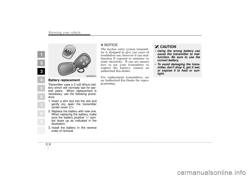
Battery replacementTransmitter uses a 3 volt lithium bat-
tery which will normally last for sev-
eral years. When replacement is
necessary, use the following proce-
dure.
1. Insert a slim tool into the slot andgently pry open the transmitter
center cover (
➀).
2. Replace the battery with new one. When replacing the battery, make
sure the battery positive “+” sym-
bol faces up as indicated in the
illustration.
3. Install the battery in the reverse order of removal.
✽ ✽NOTICEThe keyless entry system transmit-
ter is designed to give you years of
troublefree use, however it can mal-
function if exposed to moisture or
static electricity. If you are unsure
how to use your transmitter or
replace the battery, contact an
authorized Kia dealer.
For replacement transmitters, see
an Authorized Kia Dealer for repro-
gramming.
2GHN3101
CAUTION
• Using the wrong battery can
cause the transmitter to mal-function. Be sure to use thecorrect battery.
To avoid damaging the trans- mitter, don't drop it, get it wet,or expose it to heat or sun-light.
➀
Page 26 of 322

315
1
2
3
4
5
6
7
8
910
Knowing your vehicle
Power windows The ignition switch must be in the ON
position for power windows to oper-
ate. Each door has a power window
switch that controls that door’s win-
dow. However, the driver has a power
window lock switch which can block
the operation of passenger windows.
If you notice buffeting and pulsation
(wind shock) with either side window
open, you should open the opposite
window slightly to reduce the condi-
tion.
✽ ✽NOTICETo prevent the power window sys-
tem from the possibility of damage,
do not open or close two windows at
the same time. This will also ensure
the longevity of the fuse.
CAUTION
Make sure hands and face are
safely out of the way beforeclosing a window.
Do not allow children to play with the power windows. Keepthe driver’s door power win-dow lock switch in the LOCKposition (depressed). Seriousinjury can result from uninten-tional window operation bythe child.
Do not extend face or arms outside through the windowopening while driving.
Always double check to make sure all arms, hands and otherobstructions are safely out ofthe way before closing a win-dow
Page 46 of 322

335
1
2
3
4
5
6
7
8
910
Knowing your vehicle
Recalling positions from memory1. Shift the transaxle lever into Pwhile the ignition switch is ON.
2. To recall the position in memory, press the desired memory button
(1 or 2) the system will beep once,
then seat and outside rearview
mirror will automatically adjust to
the stored positions.
Adjusting one of the control knobs for
the seat or outside rearview mirror
while the system is recalling the
stored positions will cause the move-
ment for that component to stop and
move in the direction that the control
knob is moved. Other components
will continue position recalling.
To stop the position recall at any
point in the recall process, press the
STOP button once. Seat and outside
rearview mirror position recalling will
stop.
Storing and recalling with
transmitterStoring with the transmitterTurn the ignition switch to LOCK from
ON and lock all the doors using the
transmitter. The seat and outside
rearview mirror positions will be
stored in the system memory.
Driver’ s position recalling with
transmitterUnlock the door with the transmitter,
positions stored in the system mem-
ory will be recalled automatically.
If using two transmitters, recalling
times may vary because stored posi-
tions in each transmitter may be dif-
ferent.
Example) If doors are locked with
transmitter A and unlocked with
transmitter B, the positions memo-
rized when unlocked with transmitter
B will be recalled and may take
slightly longer than if unlocked with
transmitter A.
CAUTION
Use caution when recalling adjustment memory while sit-ting in the vehicle. Press theSTOP button immediately if theseat moves too far in any direc-tion.
Page 47 of 322

Knowing your vehicle36
3
1
2
3
4
5
6
7
8
910
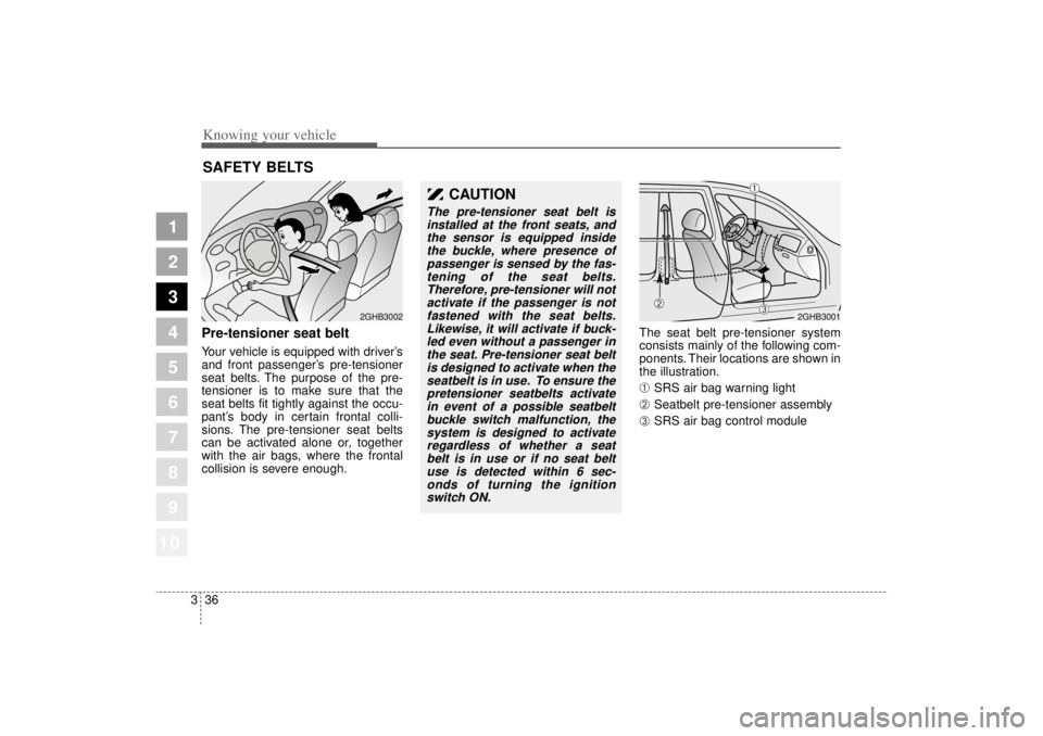
Pre-tensioner seat beltYour vehicle is equipped with driver’s
and front passenger’s pre-tensioner
seat belts. The purpose of the pre-
tensioner is to make sure that the
seat belts fit tightly against the occu-
pant’s body in certain frontal colli-
sions. The pre-tensioner seat belts
can be activated alone or, together
with the air bags, where the frontal
collision is severe enough. The seat belt pre-tensioner system
consists mainly of the following com-
ponents. Their locations are shown in
the illustration.
➀
SRS air bag warning light
➁
Seatbelt pre-tensioner assembly
➂
SRS air bag control module
SAFETY BELTS
2GHB3002
CAUTION
The pre-tensioner seat belt is
installed at the front seats, andthe sensor is equipped insidethe buckle, where presence ofpassenger is sensed by the fas-tening of the seat belts.Therefore, pre-tensioner will notactivate if the passenger is notfastened with the seat belts.Likewise, it will activate if buck-led even without a passenger inthe seat. Pre-tensioner seat beltis designed to activate when theseatbelt is in use. To ensure thepretensioner seatbelts activatein event of a possible seatbeltbuckle switch malfunction, thesystem is designed to activateregardless of whether a seatbelt is in use or if no seat beltuse is detected within 6 sec-onds of turning the ignitionswitch ON.
2GHB3001
➀
➁
➂