Page 1895 of 3383

EM-4Revision: November 2009
PRECAUTIONS
2006 QX56
�Before starting engine, apply fuel pressure to fuel lines with turning ignition switch ON (with engine
stopped). Then make sure that there are no leaks at fuel line connections.
�After repairing, start engine and increase engine speed to check engine coolant, fuel, oil, and exhaust
systems for leakage.
Parts Requiring Angular TighteningEBS00REO
�For final tightening of the following engine parts use Tool:
–Cylinder head bolts
–Main bearing cap bolts
–Connecting rod cap bolts
–Crankshaft pulley bolt (No angle wrench is required as the bolt flange is provided with notches for angle
tightening)
�Do not use a torque value for final tightening.
�The torque value for these parts are for a preliminary step.
�Ensure thread and seat surfaces are clean and lightly coated with engine oil.
Precautions for Liquid GasketEBS00REP
REMOVAL OF LIQUID GASKET SEALING
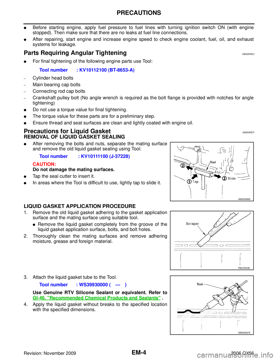
�After removing the bolts and nuts, separate the mating surface
and remove the old liquid gasket sealing using Tool.
CAUTION:
Do not damage the mating surfaces.
�Tap the seal cutter to insert it.
�In areas where the Tool is difficult to use, lightly tap to slide it.
LIQUID GASKET APPLICATION PROCEDURE
1. Remove the old liquid gasket adhering to the gasket applicationsurface and the mating surface using suitable tool.
�Remove the liquid gasket completely from the groove of the
liquid gasket application surface, bolts, and bolt holes.
2. Thoroughly clean the mating surfaces and remove adhering moisture, grease and foreign material.
3. Attach the liquid gasket tube to the Tool. Use Genuine RTV Silicone Sealant or equivalent. Refer to
GI-46, "
Recommended Chemical Products and Sealants" .
4. Apply the liquid gasket without breaks to the specified location with the specified dimensions.Tool number : KV10112100 (BT-8653-A)
Tool number : KV10111100 (J-37228)
WBIA0566E
PBIC0003E
Tool number : WS39930000 ( — )
WBIA0567E
Page 1911 of 3383
EM-20Revision: November 2009
INTAKE MANIFOLD
2006 QX56
5. Install the quick connector cap on the quick connector joint (onengine side only).
6. Install the fuel hose and tube to hose clamps.
7. Refill the engine coolant. Refer to CO-11, "
REFILLING ENGINE
COOLANT" .
INSPECTION AFTER INSTALLATION
�After installing fuel tubes, make sure there is no fuel leakage at connections in the following steps.
–Apply fuel pressure to fuel lines by turning ignition switch ON (with engine stopped). Then check for fuel
leaks at connections.
–Start the engine and rev it up and check for fuel leaks at the connections.
�Perform procedures for “Throttle Valve Closed Position Learning ” after finishing repairs. Refer to EC-78,
"Throttle Valve Closed Position Learning" .
�If electric throttle control actuator is replaced, perform procedures for “Idle Air Volume Learning” after fin-
ishing repairs. Refer to EC-78, "
Idle Air Volume Learning" .
SBIA0354E
Page 1919 of 3383
EM-28Revision: November 2009
IGNITION COIL
2006 QX56
IGNITION COILPFP:22448
Removal and InstallationEBS00RF3
REMOVAL
1. Remove the engine room cover using power tool. Refer to EM-12, "REMOVAL" .
2. Disconnect the harness connector from the ignition coil.
3. Remove the ignition coil. CAUTION:
Do not shock ignition coil.
INSTALLATION
Installation is in the reverse order of removal.
1. Ignition coil 2. Spark plug
KBIA2505E
Page 1920 of 3383
SPARK PLUG (PLATINUM-TIPPED TYPE)EM-29
C
DE
F
G H
I
J
K L
M A
EM
Revision: November 2009 2006 QX56
SPARK PLUG (PLATINUM-TIPPED TYPE)PFP:22401
Removal and InstallationEBS00RF4
REMOVAL
1. Remove the ignition coil. Refer to EM-28, "REMOVAL" .
2. Remove the spark plug using suitable tool.
INSPECTION AFTER REMOVAL
�Do not use a wire brush for cleaning.
�If the spark plug tip is covered with carbon, a spark plug cleaner may be used.
1. Ignition coil 2. Spark plug
KBIA2505E
SEM294A
SMA773C
Cleaner air pressure
: Less than 588 kPa (5.9 bar, 6 kg/cm2 , 85 psi)
Cleaning time : Less than 20 seconds
Page 1925 of 3383

EM-34Revision: November 2009
FUEL INJECTOR AND FUEL TUBE
2006 QX56
�Make sure that O-ring and its mating part are free of foreign material.
�When installing O-ring, be careful not to scratch it with tool or fingernails. Also be careful not to
twist or stretch O-ring.
�If O-ring was stretched while it was being attached, do not insert it quickly into fuel tube.
�Insert new O-ring straight into fuel tube. Do not twist it.
6. Installation of the remaining components is in the reverse order of removal.
INSPECTION AFTER INSTALLATION
After installing the fuel tubes, make sure there are no fuel leaks at the connections using the following steps.
1. Apply fuel pressure to the fuel lines by turning ignition switch ON (with engine stopped). Then check for fuel leaks at the connections.
NOTE:
Use mirrors for checking on hidden points.
2. Start the engine and rev it up and check for fuel leaks at the connections.
CAUTION:
Do not touch the engine immediately after stopping, as engine becomes extremely hot.
Page 1926 of 3383
ROCKER COVEREM-35
C
DE
F
G H
I
J
K L
M A
EM
Revision: November 2009 2006 QX56
ROCKER COVERPFP:13264
Removal and InstallationEBS00RF6
REMOVAL
1. Remove the engine room cover using power tool. Refer to EM-12, "REMOVAL" .
2. Remove the air duct and resonator assembly. Refer to EM-15, "
REMOVAL" (for LH only).
3. Move the harness on the upper rocker cover and its peripheral aside.
4. Remove the electric throttle control actuator, loosening the bolts diagonally (for LH only).
5. Remove the ignition coils. Refer to EM-28, "
REMOVAL" .
6. Remove the PCV hose from the PCV control valves.
�⇐ : Engine front
7. Loosen the bolts in reverse order shown using power tool for rocker cover (A) or (B).
CAUTION:
Do not hold the rocker cover (RH) (B) by the oil filler neck.
1. Rocker cover (LH) 2. PCV control valve3. O-ring
4. Rocker cover gasket (LH) 5. Rocker cover (RH)6. PCV control valve
7. O-ring 8. Oil filler cap9. Rocker cover gasket (RH)
KBIA2508E
WBIA0697E
Page 1929 of 3383

EM-38Revision: November 2009
TIMING CHAIN
2006 QX56
NOTE:
�To remove timing chain and associated parts, start with those on the LH bank. The procedure for remov-
ing parts on the RH bank is omitted because it is the same as that for removal on the LH bank.
�To install timing chain and associated parts, start with those on the RH bank. The procedure for installing
parts on the LH bank is omitted because it is the same as that for installation on the RH bank.
REMOVAL
1. Remove the engine assembly from the vehicle. Refer to EM-74, "REMOVAL" .
2. Remove the following components and related parts:
�Drive belt auto tensioner and idler pulley. Refer to EM-13, "REMOVAL" .
�Thermostat housing and water hose. Refer toCO-21, "Removal of Thermostat Housing, Water Outlet
and Heater Pipe" .
�Power steering oil pump bracket. Refer to PS-21, "REMOVAL" .
�Oil pan (lower), (upper) and oil strainer. Refer to EM-24, "REMOVAL" .
�Ignition coil. Refer to EM-28, "REMOVAL" .
�Rocker cover. Refer to EM-35, "REMOVAL" .
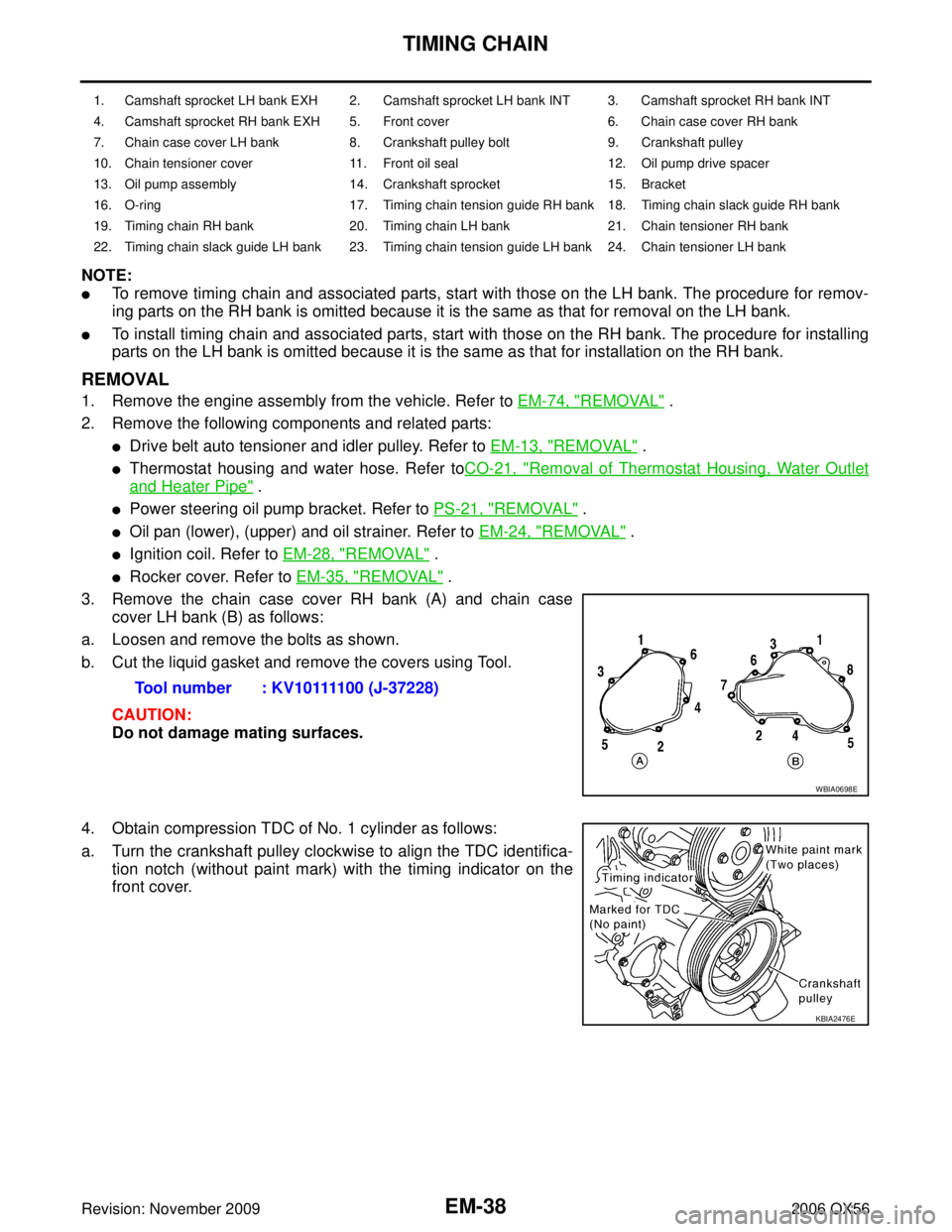
3. Remove the chain case cover RH bank (A) and chain case cover LH bank (B) as follows:
a. Loosen and remove the bolts as shown.
b. Cut the liquid gasket and remove the covers using Tool.
CAUTION:
Do not damage mating surfaces.
4. Obtain compression TDC of No. 1 cylinder as follows:
a. Turn the crankshaft pulley clockwise to align the TDC identifica- tion notch (without paint mark) with the timing indicator on the
front cover.
1. Camshaft sprocket LH bank EXH 2. Camshaft sprocket LH bank INT 3. Camshaft sprocket RH bank INT
4. Camshaft sprocket RH bank EXH 5. Front cover 6. Chain case cover RH bank
7. Chain case cover LH bank 8. Crankshaft pulley bolt 9. Crankshaft pulley
10. Chain tensioner cover 11. Front oil seal 12. Oil pump drive spacer
13. Oil pump assembly 14. Crankshaft sprocket 15. Bracket
16. O-ring 17. Timing chain tension guide RH bank 18. Timing chain slack guide RH bank
19. Timing chain RH bank 20. Timing chain LH bank 21. Chain tensioner RH bank
22. Timing chain slack guide LH bank 23. Timing chain tension guide LH bank 24. Chain tensioner LH bank
Tool number : KV10111100 (J-37228)
WBIA0698E
KBIA2476E
Page 1954 of 3383

CYLINDER HEADEM-63
C
DE
F
G H
I
J
K L
M A
EM
Revision: November 2009 2006 QX56
CYLINDER HEADPFP:11041
On-Vehicle ServiceEBS00RFD
CHECKING COMPRESSION PRESSURE
1. Warm up the engine thoroughly. Then stop the engine.
2. Release the fuel pressure. Refer to EC-80, "
FUEL PRESSURE RELEASE" .
CAUTION:
If CONSULT-II is not used to release fuel pressure leave the fuel pump fuse disconnected until
step 7.
3. Remove the spark plug from each cylinder. Refer to EM-29, "
Removal and Installation" .
4. Connect the engine tachometer (not required in use of CONSULT-II).
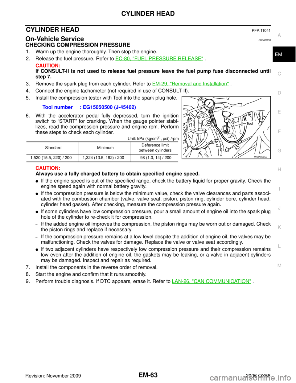
5. Install the compression tester with Tool into the spark plug hole.
6. With the accelerator pedal fully depressed, turn the ignition switch to “START” for cranking. When the gauge pointer stabi-
lizes, read the compression pressure and engine rpm. Perform
these steps to check each cylinder.
Unit: kPa (kg/cm2 , psi) /rpm
CAUTION:
Always use a fully charged battery to obtain specified engine speed.
�If the engine speed is out of the specified range, check the battery liquid for proper gravity. Check the
engine speed again with normal battery gravity.
�If the compression pressure is below the minimum value, check the valve clearances and parts associ-
ated with the combustion chamber (valve, valve seat, piston, piston ring, cylinder bore, cylinder head,
cylinder head gasket). After checking, measure the compression pressure again.
�If some cylinders have low compression pressure, pour a small amount of engine oil into the spark plug
hole of the cylinder to re-check it for compression.
–If the added engine oil improves the compression, the piston rings may be worn out or damaged. Check
the piston rings and replace if necessary.
–If the compression pressure remains at a low level despite the addition of engine oil, the valves may be
malfunctioning. Check the valves for damage. Replace the valve or valve seat accordingly.
�If two adjacent cylinders have respectively low compression pressure and their compression remains
low even after the addition of engine oil, the gaskets may be leaking, or a valve in adjacent cylinders
may be damaged. Inspect and repair as required.
7. Install the components in the reverse order of removal.
8. Start the engine and confirm that it runs smoothly.
9. Perform trouble diagnosis. If DTC appears, erase it. Refer to LAN-26, "
CAN COMMUNICATION" .
Tool number : EG15050500 (J-45402)
Standard
MinimumDeference limit
between cylinders
1,520 (15.5, 220) / 200 1,324 (13.5, 192) / 200 98 (1.0, 14) / 200
WBIA0605E