Page 412 of 3383

PRECAUTIONSATC-11
C
DE
F
G H
I
K L
M A
B
AT C
Revision: November 2009 2006 QX56
Precautions for Servicing CompressorEJS003WV
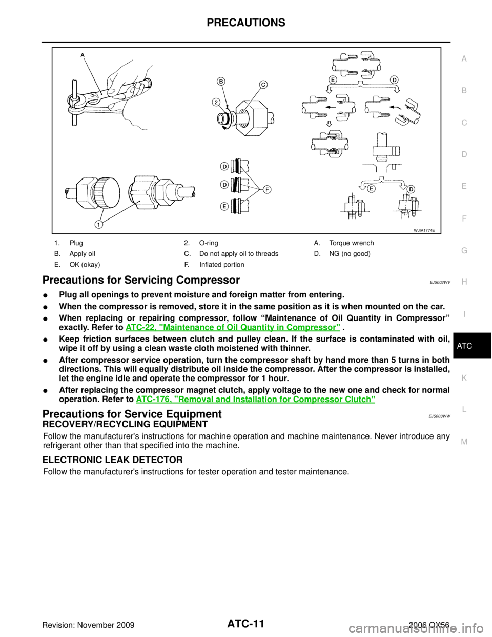
�Plug all openings to prevent moisture and foreign matter from entering.
�When the compressor is removed, store it in the same position as it is when mounted on the car.
�When replacing or repairing compressor, follow “Maintenance of Oil Quantity in Compressor”
exactly. Refer to AT C - 2 2 , "
Maintenance of Oil Quantity in Compressor" .
�Keep friction surfaces between clutch and pulley clean. If the surface is contaminated with oil,
wipe it off by using a clean waste cloth moistened with thinner.
�After compressor service operation, turn the compressor shaft by hand more than 5 turns in both
directions. This will equally distribute oil inside the compressor. After the compressor is installed,
let the engine idle and operate the compressor for 1 hour.
�After replacing the compressor magnet clutch, apply voltage to the new one and check for normal
operation. Refer to ATC-176, "
Removal and Installation for Compressor Clutch"
Precautions for Service EquipmentEJS003WW
RECOVERY/RECYCLING EQUIPMENT
Follow the manufacturer's instructions for machine operation and machine maintenance. Never introduce any
refrigerant other than that specified into the machine.
ELECTRONIC LEAK DETECTOR
Follow the manufacturer's instructions for tester operation and tester maintenance.
1. Plug 2. O-ringA. Torque wrench
B. Apply oil C. Do not apply oil to threadsD. NG (no good)
E. OK (okay) F. Inflated portion
WJIA1774E
Page 413 of 3383

ATC-12
PRECAUTIONS
Revision: November 20092006 QX56
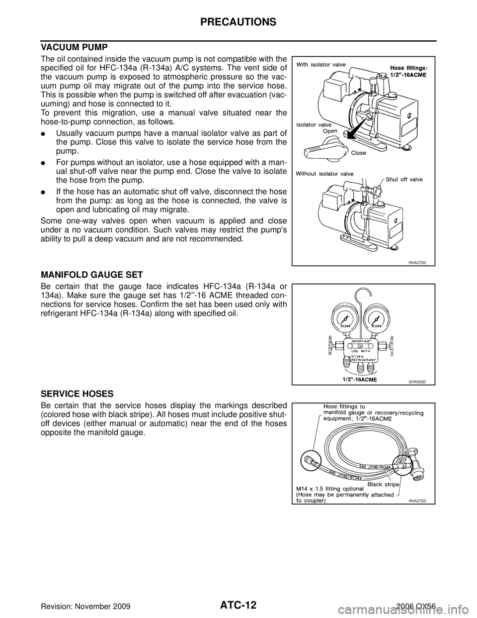
VACUUM PUMP
The oil contained inside the vacuum pump is not compatible with the
specified oil for HFC-134a (R-134a) A/C systems. The vent side of
the vacuum pump is exposed to atmospheric pressure so the vac-
uum pump oil may migrate out of the pump into the service hose.
This is possible when the pump is switched off after evacuation (vac-
uuming) and hose is connected to it.
To prevent this migration, use a manual valve situated near the
hose-to-pump connection, as follows.
�Usually vacuum pumps have a manual isolator valve as part of
the pump. Close this valve to isolate the service hose from the
pump.
�For pumps without an isolator, use a hose equipped with a man-
ual shut-off valve near the pump end. Close the valve to isolate
the hose from the pump.
�If the hose has an automatic shut off valve, disconnect the hose
from the pump: as long as the hose is connected, the valve is
open and lubricating oil may migrate.
Some one-way valves open when vacuum is applied and close
under a no vacuum condition. Such valves may restrict the pump's
ability to pull a deep vacuum and are not recommended.
MANIFOLD GAUGE SET
Be certain that the gauge face indicates HFC-134a (R-134a or
134a). Make sure the gauge set has 1/2 ″-16 ACME threaded con-
nections for service hoses. Confirm the set has been used only with
refrigerant HFC-134a (R-134a) along with specified oil.
SERVICE HOSES
Be certain that the service hoses display the markings described
(colored hose with black stripe). All hoses must include positive shut-
off devices (either manual or automatic) near the end of the hoses
opposite the manifold gauge.
RHA270D
SHA533D
RHA272D
Page 414 of 3383
PRECAUTIONSATC-13
C
DE
F
G H
I
K L
M A
B
AT C
Revision: November 2009 2006 QX56
SERVICE COUPLERS
Never attempt to connect HFC-134a (R-134a) service couplers to a
CFC-12 (R-12) A/C system. The HFC-134a (R-134a) couplers will
not properly connect to the CFC-12 (R-12) system. If an improper
connection is attempted, discharging and contamination may occur.
REFRIGERANT WEIGHT SCALE
Verify that no refrigerant other than HFC134a (R-134a) and specified
oils have been used with the scale. If the scale controls refrigerant
flow electronically, the hose fitting must be 1/2”-16 ACME.
CHARGING CYLINDER
Using a charging cylinder is not recommended. Refrigerant may be vented into air from cylinder's top valve
when filling the cylinder with refrigerant. Also, the accuracy of the cylinder is generally less than that of an
electronic scale or of quality recycle/recharge equipment.
Shut-off valve rotationA/C service valve
Clockwise Open
Counterclockwise Close
RHA273D
RHA274D
Page 415 of 3383

ATC-14
PREPARATION
Revision: November 20092006 QX56
PREPARATIONPFP:00002
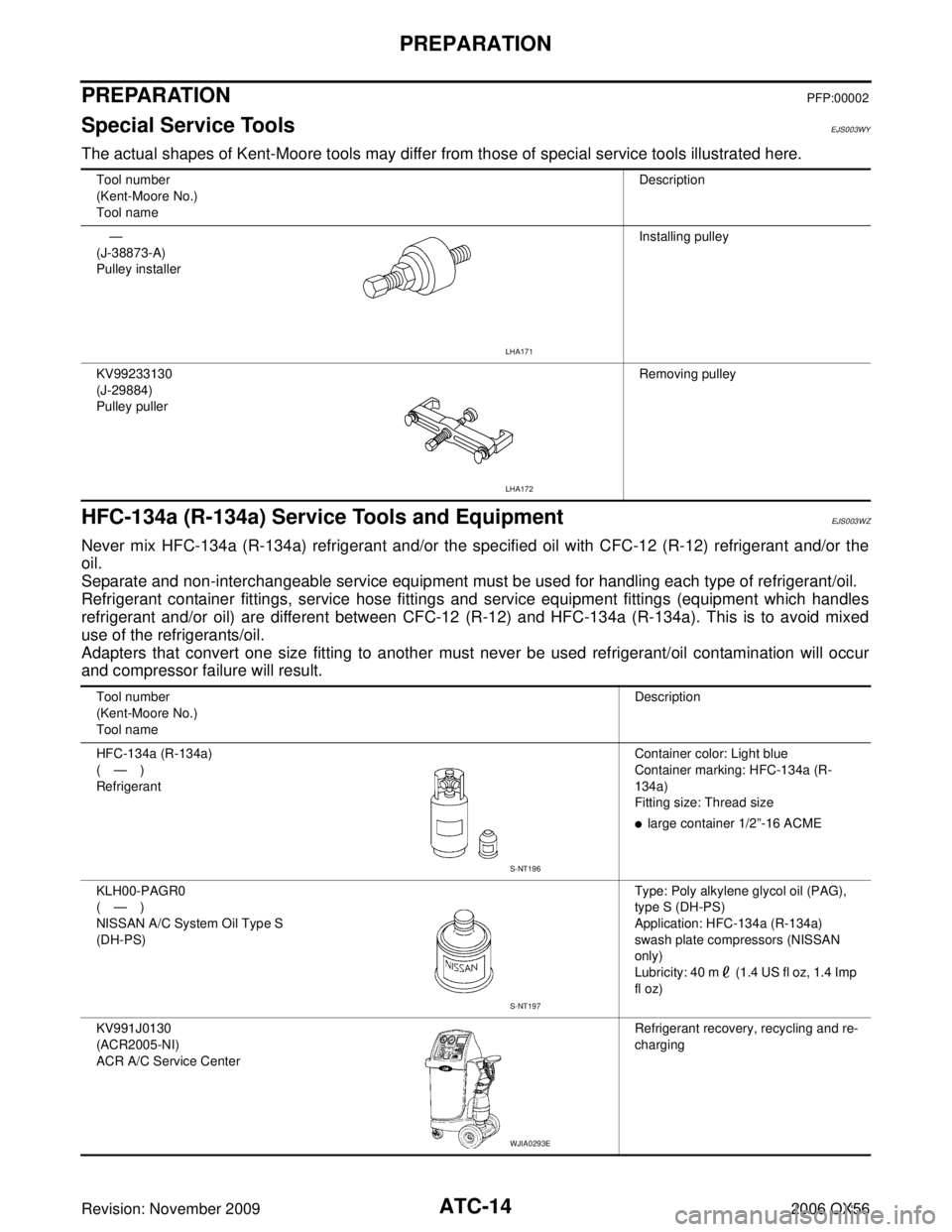
Special Service ToolsEJS003WY
The actual shapes of Kent-Moore tools may differ from those of special service tools illustrated here.
HFC-134a (R-134a) Service Tools and EquipmentEJS003WZ
Never mix HFC-134a (R-134a) refrigerant and/or the specified oil with CFC-12 (R-12) refrigerant and/or the
oil.
Separate and non-interchangeable service equipment must be used for handling each type of refrigerant/oil.
Refrigerant container fittings, service hose fittings and service equipment fittings (equipment which handles
refrigerant and/or oil) are different between CFC-12 (R-12) and HFC-134a (R-134a). This is to avoid mixed
use of the refrigerants/oil.
Adapters that convert one size fitting to another must never be used refrigerant/oil contamination will occur
and compressor failure will result.
Tool number
(Kent-Moore No.)
Tool nameDescription
—
(J-38873-A)
Pulley installer Installing pulley
KV99233130
(J-29884)
Pulley puller Removing pulley
LHA171
LHA172
Tool number
(Kent-Moore No.)
Tool nameDescription
HFC-134a (R-134a)
( — )
Refrigerant Container color: Light blue
Container marking: HFC-134a (R-
134a)
Fitting size: Thread size
�large container 1/2
”-16 ACME
KLH00-PAGR0
( — )
NISSAN A/C System Oil Type S
(DH-PS) Type: Poly alkylene glycol oil (PAG),
type S (DH-PS)
Application: HFC-134a (R-134a)
swash plate compressors (NISSAN
only)
Lubricity: 40 m (1.4 US fl oz, 1.4 Imp
fl oz)
KV991J0130
(ACR2005-NI)
ACR A/C Service Center Refrigerant recovery, recycling and re-
charging
S-NT196
S-NT197
WJIA0293E
Page 417 of 3383

ATC-16
PREPARATION
Revision: November 20092006 QX56
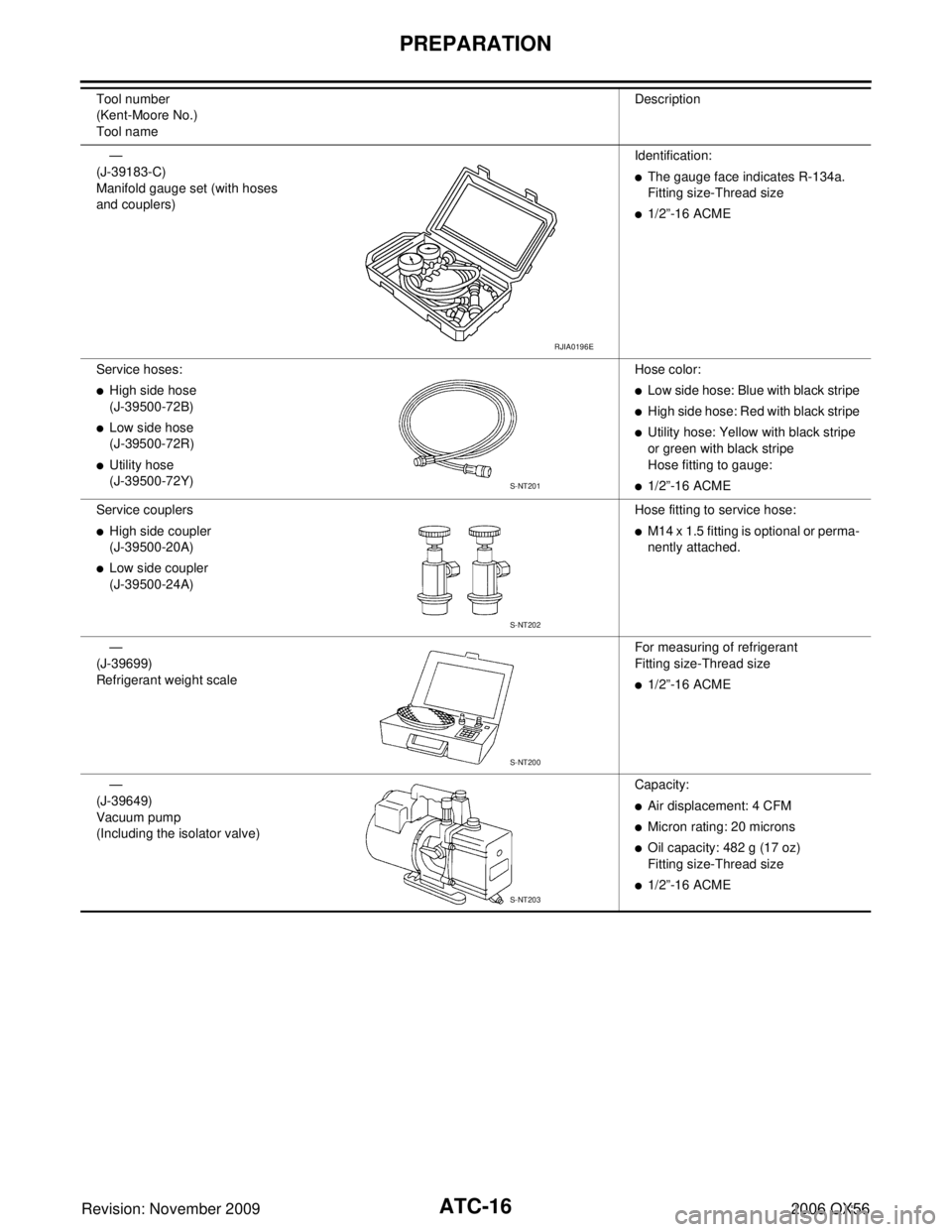
—
(J-39183-C)
Manifold gauge set (with hoses
and couplers) Identification:
�The gauge face indicates R-134a.
Fitting size-Thread size
�1/2”
-16 ACME
Service hoses:
�High side hose
(J-39500-72B)
�Low side hose
(J-39500-72R)
�Utility hose
(J-39500-72Y) Hose color:
�Low side hose: Blue with black stripe
�High side hose: Red with black stripe
�Utility hose: Yellow with black stripe
or green with black stripe
Hose fitting to gauge:
�1/2”
-16 ACME
Service couplers
�High side coupler
(J-39500-20A)
�Low side coupler
(J-39500-24A) Hose fitting to service hose:
�M14 x 1.5 fitting is optional or perma-
nently attached.
—
(J-39699)
Refrigerant weight scale For measuring of refrigerant
Fitting size-Thread size
�1/2”
-16 ACME
—
(J-39649)
Vacuum pump
(Including the isolator valve) Capacity:
�Air displacement: 4 CFM
�Micron rating: 20 microns
�Oil capacity: 482 g (17 oz)
Fitting size-Thread size
�1/2”
-16 ACME
Tool number
(Kent-Moore No.)
Tool name
Description
RJIA0196E
S-NT201
S-NT202
S-NT200
S-NT203
Page 418 of 3383
PREPARATIONATC-17
C
DE
F
G H
I
K L
M A
B
AT C
Revision: November 2009 2006 QX56
Commercial Service ToolsEJS003X0
Tool nameDescription
(J-41810-NI)
Refrigerant identifier equipment (R-
134a) For checking refrigerant purity and
system contamination
Power tool Loosening bolts and nuts
(J-44614)
Clutch disc holding tool Clutch disc holding tool
RJIA0197E
PBIC0190E
WHA230
Page 572 of 3383

REFRIGERANT LINESATC-171
C
DE
F
G H
I
K L
M A
B
AT C
Revision: November 2009 2006 QX56
REFRIGERANT LINESPFP:92600
HFC-134a (R-134a) Service ProcedureEJS003YR
SETTING OF SERVICE TOOLS AND EQUIPMENT
Discharging Refrigerant
WARNING:
Avoid breathing A/C refrigerant and oil vapor or mist. Exposure may irritate eyes, nose and throat.
Remove HFC-134a (R-134a) refrigerant from the A/C system using certified service equipment meeting
requirements of SAE J2210 HFC-134a (R-134a) recycling equipment or SAE J2201 HFC-134a (R-134a)
recovery equipment. If an accidental system discharge occurs, ventilate the work area before resum-
ing service. Additional health and safety information may be obtained from the refrigerant and oil man-
ufacturers.
Evacuating System and Charging Refrigerant
1. Shut-off valve2. A/C service valve 3. Recovery/recycling equipment
WJIA0579E
1. Shut-off valve 2. A/C service valve3. Recovery/recycling equipment
4. Refrigerant container (HFC-134a) 5. Weight scale (J-39650) 6. Evacuating vacuum pump (J-39699)
7. Manifold gauge set (J-39183)
WJIA0580E
Page 575 of 3383
ATC-174
REFRIGERANT LINES
Revision: November 20092006 QX56
Rear A/C
NOTE:
Refer to AT C - 7 , "
Precautions for Refrigerant Connection" .
1. High-pressure service valve 2. Grommet 3. High-pressure pipe
4. Refrigerant pressure sensor 5. Condenser 6. Compressor shaft seal
7. High-pressure flexible hose 8. Low-pressure flexible hose 9. Low-pressure service valve
10. Low-pressure pipe 11. Expansion valve (front) 12. Drain hose
WJIA2315E
1. Rear heater and cooling unit assembly 2. Rear A/C pipes 3. Rear A/C heater core pipes
4. Rear heater core hose 5. Rear blower motor6. Underfloor rear A/C pipes
7. Underfloor rear heater core pipes A. Bolt torque specifications B. Leak checking order (l - r)
C. Tightening torque D. Wrench sizeE. O-ring size
⇐ Front
NOTE: The O-ring size 8 is the high-side and the O-ring size 16 is the low-side.