Page 945 of 3383
BL-164
BODY REPAIR
Revision: November 20092006 QX56
1. Front fender (RH, LH)
2. Hood assembly
3. Rear hoodledge reinforcement (RH, LH)
4. Outer sill reinforcement (RH, LH)
5. Front pillar hinge brace (RH, LH)
6. Center pillar hinge brace
7. Outer front pillar reinforcement (RH, LH)
8. Center inner pillar (RH, LH)
9. Front inner pillar upper (RH, LH)
10. Inner roof side rail (RH, LH)
11. Roof with sunroof opening
12. Roof
13. Front roof rail
14. Sunroof reinforcement
15. Roof 1st bow
16. Roof 2nd bow
17. Roof 3rd bow
18. Roof 4th bow
19. Rear roof rail
20. Main back pillar (RH, LH)
21. Back pillar reinforcement (RH, LH)
22. Rear inner side panel (RH, LH)
23. Rear wheel housing (RH, LH)
24. Rear body side outer (RH, LH)
25. Front body side outer (RH, LH)
26. Front door assembly (RH, LH)
27. Rear door assembly (RH, LH)
28. Lift gate assembly
Page 948 of 3383
BODY REPAIRBL-167
C
DE
F
G H
J
K L
M A
B
BL
Revision: November 2009 2006 QX56
UNDERCOATING
The underside of the floor and wheelhouse are undercoated to prevent rust, vibration, noise and stone chip-
ping. Therefore, when such a panel is replaced or repaired, apply undercoating to that part. Use an undercoat-
ing which is rust preventive, soundproof, vibration-proof, shock-resistant, adhesive, and durable.
Precautions in undercoating
1. Do not apply undercoating to any place unless specified (such as the areas above the muffler and three
way catalyst which are subjected to heat).
2. Do not undercoat the exhaust pipe or other parts which become hot.
3. Do not undercoat rotating parts.
4. Apply bitumen wax after applying undercoating.
LIIA0129E
Page 973 of 3383
BL-192
BODY REPAIR
Revision: November 20092006 QX56
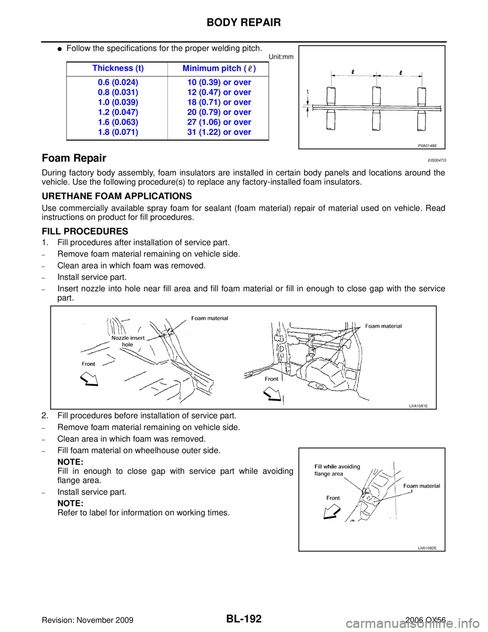
�Follow the specifications for the proper welding pitch.
Unit:mm
Foam RepairEIS004TG
During factory body assembly, foam insulators are installed in certain body panels and locations around the
vehicle. Use the following procedure(s) to replace any factory-installed foam insulators.
URETHANE FOAM APPLICATIONS
Use commercially available spray foam for sealant (foam material) repair of material used on vehicle. Read
instructions on product for fill procedures.
FILL PROCEDURES
1. Fill procedures after installation of service part.
–Remove foam material remaining on vehicle side.
–Clean area in which foam was removed.
–Install service part.
–Insert nozzle into hole near fill area and fill foam material or fill in enough to close gap with the service
part.
2. Fill procedures before installation of service part.
–Remove foam material remaining on vehicle side.
–Clean area in which foam was removed.
–Fill foam material on wheelhouse outer side.
NOTE:
Fill in enough to close gap with service part while avoiding
flange area.
–Install service part.
NOTE:
Refer to label for information on working times. Thickness (t)
Minimum pitch ( )
0.6 (0.024)
0.8 (0.031)
1.0 (0.039)
1.2 (0.047)
1.6 (0.063)
1.8 (0.071) 10 (0.39) or over
12 (0.47) or over
18 (0.71) or over
20 (0.79) or over
27 (1.06) or over
31 (1.22) or over
PIIA0148E
LIIA1081E
LIIA1082E
Page 996 of 3383
PRECAUTIONSBR-3
C
DE
G H
I
J
K L
M A
B
BR
Revision: November 2009 2006 QX56
PRECAUTIONSPFP:00001
Precautions for Supplemental Restraint System (SRS) “AIR BAG” and “SEAT
BELT PRE-TENSIONER”
EFS004VW
The Supplemental Restraint System such as “AIR BAG” and “SEAT BELT PRE-TENSIONER ”, used along
with a front seat belt, helps to reduce the risk or severity of injury to the driver and front passenger for certain
types of collision. This system includes seat belt switch inputs and dual stage front air bag modules. The SRS
system uses the seat belt switches to determine the front air bag deployment, and may only deploy one front
air bag, depending on the severity of a collision and whether the front occupants are belted or unbelted.
Information necessary to service the system safely is included in the SRS and SB section of this Service Man-
ual.
WARNING:
�To avoid rendering the SRS inoperative, which could increase the risk of personal injury or death
in the event of a collision which would result in air bag inflation, all maintenance must be per-
formed by an authorized NISSAN/INFINITI dealer.
�Improper maintenance, including incorrect removal and installation of the SRS, can lead to per-
sonal injury caused by unintentional activation of the system. For removal of Spiral Cable and Air
Bag Module, see the SRS section.
�Do not use electrical test equipment on any circuit related to the SRS unless instructed to in this
Service Manual. SRS wiring harnesses can be identified by yellow and/or orange harnesses or
harness connectors.
Precautions for Brake SystemEFS004VX
�Always use recommended brake fluid. Refer to MA-11, "RECOMMENDED FLUIDS AND LUBRICANTS" .
�Do not reuse drained brake fluid.
�Be careful not to splash brake fluid on painted areas.
�To clean or wash all parts of master cylinder, disc brake caliper and wheel cylinder, use clean brake fluid.
�Do not use mineral oils such as gasoline or kerosene. They will ruin rubber parts of the hydraulic system.
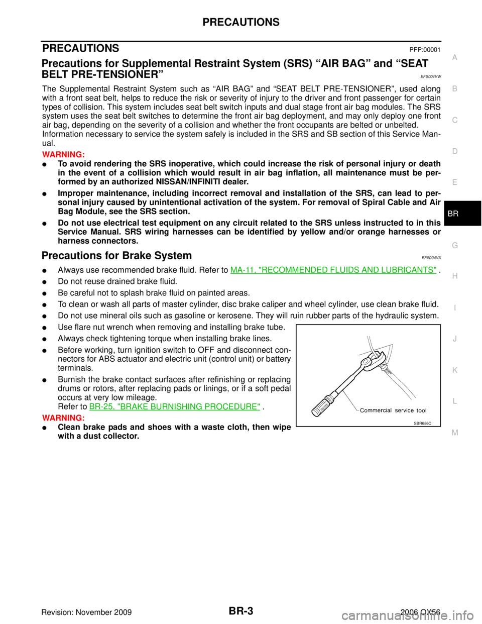
�Use flare nut wrench when removing and installing brake tube.
�Always check tightening torque when installing brake lines.
�Before working, turn ignition switch to OFF and disconnect con-
nectors for ABS actuator and electric unit (control unit) or battery
terminals.
�Burnish the brake contact surfaces after refinishing or replacing
drums or rotors, after replacing pads or linings, or if a soft pedal
occurs at very low mileage.
Refer to BR-25, "
BRAKE BURNISHING PROCEDURE" .
WARNING:
�Clean brake pads and shoes with a waste cloth, then wipe
with a dust collector.SBR686C
Page 998 of 3383
NOISE, VIBRATION, AND HARSHNESS (NVH) TROUBLESHOOTINGBR-5
C
DE
G H
I
J
K L
M A
B
BR
Revision: November 2009 2006 QX56
NOISE, VIBRATION, AND HARSHNESS (NVH) TROUBLESHOOTINGPFP:00003
NVH Troubleshooting ChartEFS004VZ
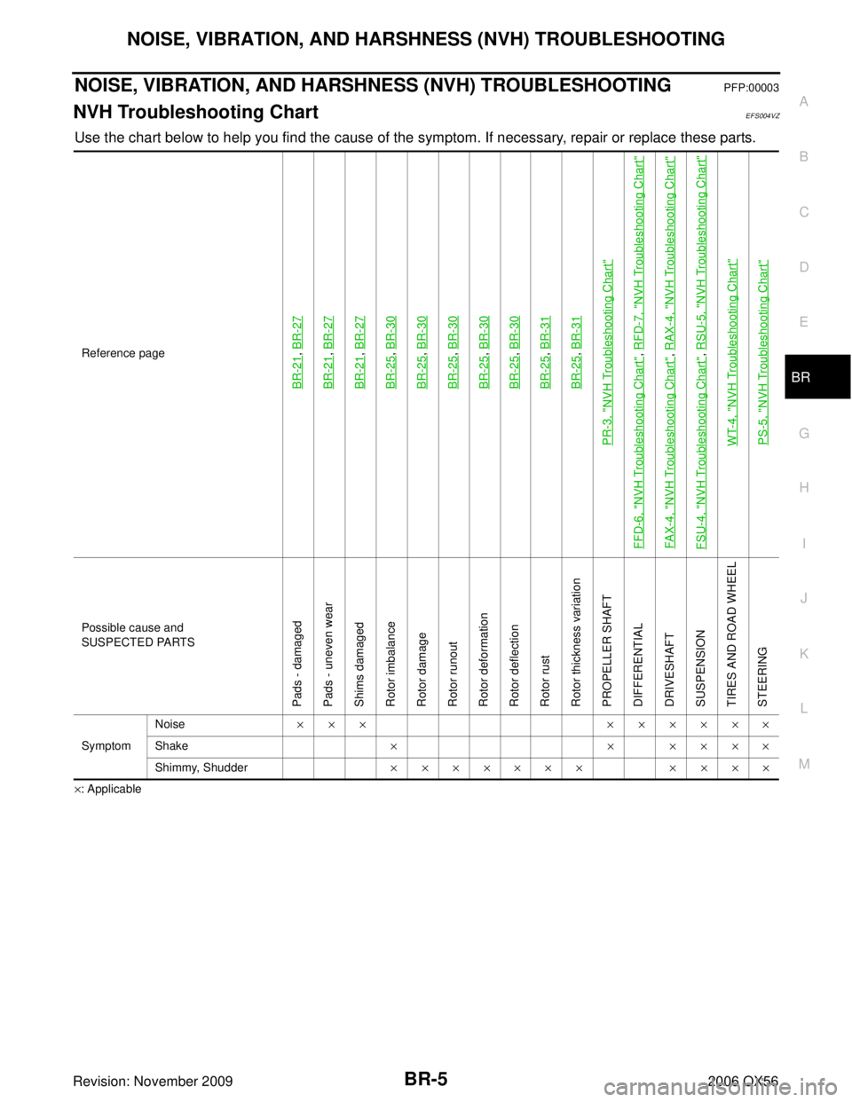
Use the chart below to help you find the cause of the symptom. If necessary, repair or replace these parts.
×: ApplicableReference page
BR-21
,
BR-27
BR-21
, BR-27
BR-21
, BR-27
BR-25
, BR-30
BR-25
, BR-30
BR-25
, BR-30
BR-25
, BR-30
BR-25
, BR-30
BR-25
, BR-31
BR-25
, BR-31
PR-3, "
NVH Troubleshooting Chart
"
FFD-6, "
NVH Troubleshooting Chart
", RFD-7, "
NVH Troubleshooting Chart
"
FAX-4, "
NVH Troubleshooting Chart
", RAX-4, "
NVH Troubleshooting Chart
"
FSU-4, "
NVH Troubleshooting Chart
", RSU-5, "
NVH Troubleshooting Chart
"
WT-4, "
NVH Troubleshooting Chart
"
PS-5, "
NVH Troubleshooting Chart
"
Possible cause and
SUSPECTED PARTS
Pads - damaged
Pads - uneven wear
Shims damaged
Rotor imbalance
Rotor damage
Rotor runout
Rotor deformation
Rotor deflection
Rotor rust
Rotor thickness variation
PROPELLER SHAFT
DIFFERENTIAL
DRIVESHAFT
SUSPENSION
TIRES AND ROAD WHEEL
STEERING
Symptom Noise
××× ××××××
Shake ××××××
Shimmy, Shudder ××××××× ××××
Page 1004 of 3383
BRAKE FLUIDBR-11
C
DE
G H
I
J
K L
M A
B
BR
Revision: November 2009 2006 QX56
Bleeding Brake SystemEFS004W4
CAUTION:
While bleeding, pay attention to master cylinder fluid level.
1. Turn ignition switch OFF and disconnect ABS actuator and electric unit (control unit) connector or battery
negative cable.
2. Connect a vinyl tube to the rear right bleed valve.
3. Fully depress brake pedal 4 to 5 times.
4. With brake pedal depressed, loosen bleed valve to let the air out, and then tighten it immediately.
5. Repeat steps 3 and 4 until no more air comes out.
6. Tighten bleed valve to the specified torque. Refer to BR-21, "
Components" (front disc brake), BR-27,
"Components" (rear disc brake).
7. Repeat steps 2 through 6 at each wheel, with master cylinder reservoir tank filled at least half way, bleed air in order from the front left, rear left, and front right bleed valves.
Page 1018 of 3383
FRONT DISC BRAKEBR-25
C
DE
G H
I
J
K L
M A
B
BR
Revision: November 2009 2006 QX56
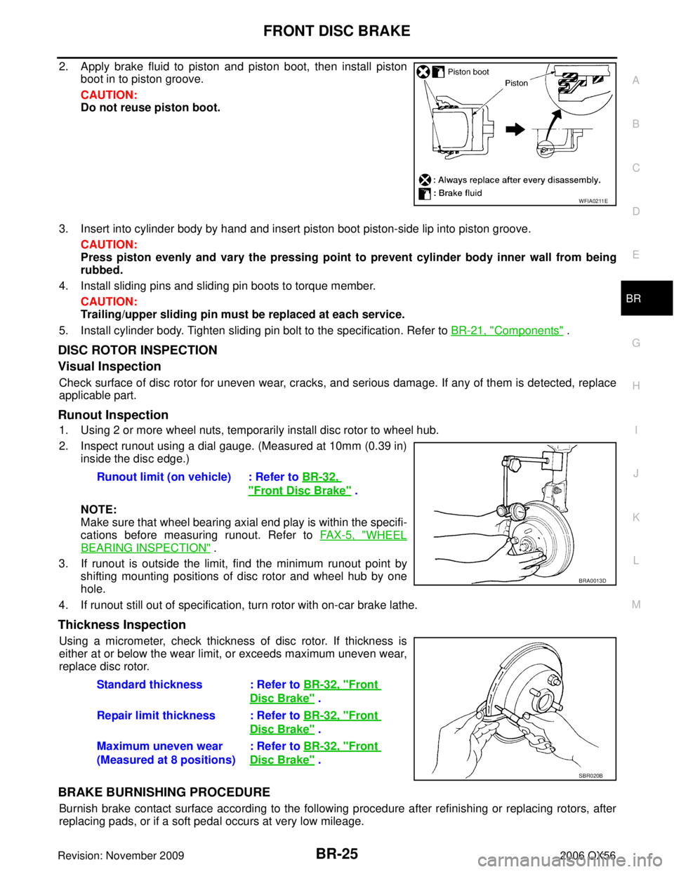
2. Apply brake fluid to piston and piston boot, then install piston
boot in to piston groove.
CAUTION:
Do not reuse piston boot.
3. Insert into cylinder body by hand and insert piston boot piston-side lip into piston groove. CAUTION:
Press piston evenly and vary the pressing point to prevent cylinder body inner wall from being
rubbed.
4. Install sliding pins and sliding pin boots to torque member.
CAUTION:
Trailing/upper sliding pin must be replaced at each service.
5. Install cylinder body. Tighten sliding pin bolt to the specification. Refer to BR-21, "
Components" .
DISC ROTOR INSPECTION
Visual Inspection
Check surface of disc rotor for uneven wear, cracks, and serious damage. If any of them is detected, replace
applicable part.
Runout Inspection
1. Using 2 or more wheel nuts, temporarily install disc rotor to wheel hub.
2. Inspect runout using a dial gauge. (Measured at 10mm (0.39 in)
inside the disc edge.)
NOTE:
Make sure that wheel bearing axial end play is within the specifi-
cations before measuring runout. Refer to FA X - 5 , "
WHEEL
BEARING INSPECTION" .
3. If runout is outside the limit, find the minimum runout point by shifting mounting positions of disc rotor and wheel hub by one
hole.
4. If runout still out of specification, turn rotor with on-car brake lathe.
Thickness Inspection
Using a micrometer, check thickness of disc rotor. If thickness is
either at or below the wear limit, or exceeds maximum uneven wear,
replace disc rotor.
BRAKE BURNISHING PROCEDURE
Burnish brake contact surface according to the following procedure after refinishing or replacing rotors, after
replacing pads, or if a soft pedal occurs at very low mileage.
WFIA0211E
Runout limit (on vehicle) : Refer to BR-32,
"Front Disc Brake" .
BRA0013D
Standard thickness : Refer to BR-32, "Front
Disc Brake" .
Repair limit thickness : Refer to BR-32, "
Front
Disc Brake" .
Maximum uneven wear
(Measured at 8 positions) : Refer to
BR-32, "
Front
Disc Brake" .
SBR020B
Page 1023 of 3383
BR-30
REAR DISC BRAKE
Revision: November 20092006 QX56
Sliding Pin Bolts and Sliding Pin Boots
Make sure there is no wear, damage, or cracks in sliding sleeve and sliding sleeve boots, and if there are,
replace them.
ASSEMBLY
CAUTION:
Do not use NISSAN Rubber Grease (KRE00 00010, KRE00 00010 01) when assembling.
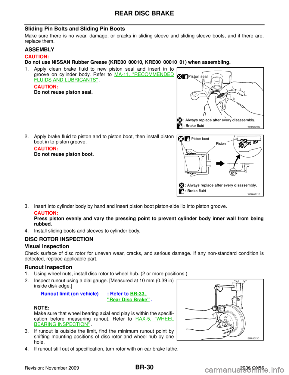
1. Apply clean brake fluid to new piston seal and insert in to
groove on cylinder body. Refer to MA-11, "
RECOMMENDED
FLUIDS AND LUBRICANTS" .
CAUTION:
Do not reuse piston seal.
2. Apply brake fluid to piston and to piston boot, then install piston boot in to piston groove.
CAUTION:
Do not reuse piston boot.
3. Insert into cylinder body by hand and insert piston boot piston-side lip into piston groove. CAUTION:
Press piston evenly and vary the pressing point to prevent cylinder body inner wall from being
rubbed.
4. Install sliding boots and sleeves to cylinder body.
DISC ROTOR INSPECTION
Visual Inspection
Check surface of disc rotor for uneven wear, cracks, and serious damage. If any non-standard condition is
detected, replace applicable part.
Runout Inspection
1. Using wheel nuts, install disc rotor to wheel hub. (2 or more positions.)
2. Inspect runout using a dial gauge. [Measured at 10 mm (0.39 in) inside disk edge.]
NOTE:
Make sure that wheel bearing axial end play is within the specifi-
cation before measuring runout. Refer to RAX-5, "
WHEEL
BEARING INSPECTION" .
3. If runout is outside the limit, find the minimum runout point by shifting mounting positions of disc rotor and wheel hub by one
hole.
4. If runout still out of specification, turn rotor with on-car brake lathe.
WFIA0210E
WFIA0211E
Runout limit (on vehicle) : Refer to BR-33,
"Rear Disc Brake" .
BRA0013D