Page 1905 of 3383
EM-14Revision: November 2009
DRIVE BELTS
2006 QX56
INSTALLATION
Installation is in the reverse order of removal.
CAUTION:
Make sure belt is securely installed around all pulleys.
�Rotate the crankshaft pulley several turns clockwise to equalize belt tension between pulleys.
�Make sure belt tension is within the allowable working range, using the indicator notch on the drive belt
auto tensioner. Refer to EM-13, "
Checking Drive Belts" .
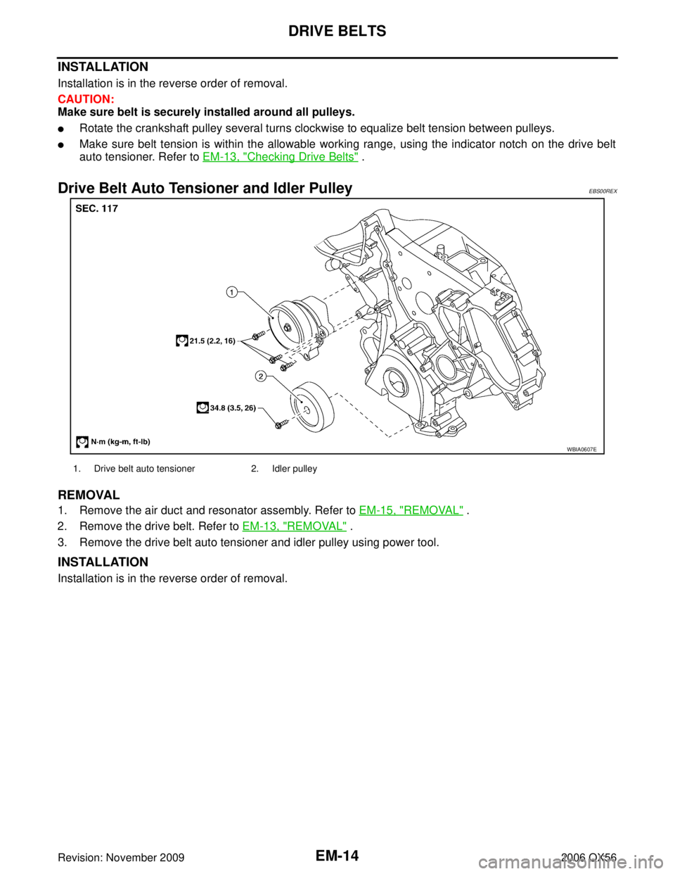
Drive Belt Auto Tensioner and Idler PulleyEBS00REX
REMOVAL
1. Remove the air duct and resonator assembly. Refer to EM-15, "REMOVAL" .
2. Remove the drive belt. Refer to EM-13, "
REMOVAL" .
3. Remove the drive belt auto tensioner and idler pulley using power tool.
INSTALLATION
Installation is in the reverse order of removal.
WBIA0607E
1. Drive belt auto tensioner 2. Idler pulley
Page 1929 of 3383

EM-38Revision: November 2009
TIMING CHAIN
2006 QX56
NOTE:
�To remove timing chain and associated parts, start with those on the LH bank. The procedure for remov-
ing parts on the RH bank is omitted because it is the same as that for removal on the LH bank.
�To install timing chain and associated parts, start with those on the RH bank. The procedure for installing
parts on the LH bank is omitted because it is the same as that for installation on the RH bank.
REMOVAL
1. Remove the engine assembly from the vehicle. Refer to EM-74, "REMOVAL" .
2. Remove the following components and related parts:
�Drive belt auto tensioner and idler pulley. Refer to EM-13, "REMOVAL" .
�Thermostat housing and water hose. Refer toCO-21, "Removal of Thermostat Housing, Water Outlet
and Heater Pipe" .
�Power steering oil pump bracket. Refer to PS-21, "REMOVAL" .
�Oil pan (lower), (upper) and oil strainer. Refer to EM-24, "REMOVAL" .
�Ignition coil. Refer to EM-28, "REMOVAL" .
�Rocker cover. Refer to EM-35, "REMOVAL" .
3. Remove the chain case cover RH bank (A) and chain case cover LH bank (B) as follows:
a. Loosen and remove the bolts as shown.
b. Cut the liquid gasket and remove the covers using Tool.
CAUTION:
Do not damage mating surfaces.
4. Obtain compression TDC of No. 1 cylinder as follows:
a. Turn the crankshaft pulley clockwise to align the TDC identifica- tion notch (without paint mark) with the timing indicator on the
front cover.
1. Camshaft sprocket LH bank EXH 2. Camshaft sprocket LH bank INT 3. Camshaft sprocket RH bank INT
4. Camshaft sprocket RH bank EXH 5. Front cover 6. Chain case cover RH bank
7. Chain case cover LH bank 8. Crankshaft pulley bolt 9. Crankshaft pulley
10. Chain tensioner cover 11. Front oil seal 12. Oil pump drive spacer
13. Oil pump assembly 14. Crankshaft sprocket 15. Bracket
16. O-ring 17. Timing chain tension guide RH bank 18. Timing chain slack guide RH bank
19. Timing chain RH bank 20. Timing chain LH bank 21. Chain tensioner RH bank
22. Timing chain slack guide LH bank 23. Timing chain tension guide LH bank 24. Chain tensioner LH bank
Tool number : KV10111100 (J-37228)
WBIA0698E
KBIA2476E
Page 1936 of 3383
TIMING CHAINEM-45
C
DE
F
G H
I
J
K L
M A
EM
Revision: November 2009 2006 QX56
a. Apply engine oil onto the threaded parts of the bolt and seating area.
b. Select the one most visible notch of the four on the bolt flange.
Corresponding to the selected notch, put a alignment mark
(such as paint) on the crankshaft pulley.
14. Rotate the crankshaft pulley in normal direction (clockwise when viewed from engine front) to check for parts interference.
15. Installation of the remaining components is in the reverse of order of removal.Crankshaft pulley bolt torque
Step 1 : 93.1 N·m (9.5 kg-m, 69 ft-lb)
Step 2 : additional 90
° (angle tightening)
KBIA2519E
Page 1937 of 3383
EM-46Revision: November 2009
CAMSHAFT
2006 QX56
CAMSHAFTPFP:13001
Removal and InstallationEBS00RF8
* Refer to GI-46, "Recommended Chemical Products and Sealants" .
REMOVAL
1. Remove the RH bank and LH bank rocker covers. Refer to EM-35, "Removal and Installation" .
2. Obtain compression TDC of No. 1 cylinder as follows:
a. Turn the crankshaft pulley clockwise to align the TDC identifica- tion notch (without paint mark) with the timing indicator on the
front cover.
1. Cylinder head (RH bank) 2. Camshaft bracket (No. 2, 3, 4, 5) 3. Valve lifter
4. Camshaft bracket (No. 1) 5. Seal washer6. Camshaft (RH bank EXH)
7. Camshaft (RH bank INT) 8. Camshaft (LH bank INT)9. Camshaft (LH bank EXH)
10. Camshaft sprocket (RH bank EXH) 11. Camshaft sprocket (RH bank INT) 12. Camshaft sprocket (LH bank INT)
13. Camshaft sprocket (LH bank EXH) 14. Camshaft position sensor (PHASE) 15. O-ring
16. Cylinder head (LH bank)
WBIA0469E
KBIA2476E
Page 1947 of 3383

EM-56Revision: November 2009
CAMSHAFT
2006 QX56
1. Warm up the engine. Then stop the engine.
2. Remove the engine cover and. Refer to EM-12, "
Removal and Installation" .
3. Remove the battery cover. Refer to SC-9, "
Removal and Installation" .
4. Remove the air cleaner and air duct assembly EM-15, "
Removal and Installation" .
5. Remove the RH bank and LH bank rocker covers using power tool. Refer to EM-35, "
REMOVAL" .
6. Turn the crankshaft pulley in the normal direction (clockwise when viewed from engine front) to align TDC identification notch
(without paint mark) with timing indicator.
7. At this time, make sure both the intake and exhaust cam noses of No. 1 cylinder (top front on LH bank) face outside.
�If they do not face outside, turn crankshaft pulley once more.
8. Measure valve clearances at the locations marked “×” as shown
in the table below (locations indicated with black arrow).
�⇐ : Engine front
�⇐ (black): Measurable at No.1 cylinder compression top dead
center
�⇐ (white): Measurable at No. 3 cylinder compression top
dead center
�A: RH
�B: LH
�C: Exhaust
�D: Intake
NOTE:
Firing order 1-8-7-3-6-5-4-2
�No. 1 cylinder compression TDC
KBIA2476E
KBIA0400J
Measuring position (RH bank) No. 2 cyl
(E) No. 4 cyl
(F) No. 6 cyl
(G) No. 8 cyl
(H)
No. 1 cylinder at TDC EXH
×
INT ××
Measuring position (LH bank) No. 1 cyl
(J) No. 3 cyl
(K) No. 5 cyl
(L) No. 7 cyl
(M)
No. 1 cylinder at TDC INT
××
EXH ××
WBIA0713E
Page 1948 of 3383

CAMSHAFTEM-57
C
DE
F
G H
I
J
K L
M A
EM
Revision: November 2009 2006 QX56
�Measure valve clearance using suitable tool.Refer to EM-105,
"Valve Clearance" .
CAUTION:
If the inspection was carried out with a cold engine, make
sure the values with a fully warmed up engine are still
within specifications.
9. Turn the crankshaft pulley clockwise 270 ° from the position of No. 1 cylinder compression TDC to obtain
No. 3 cylinder compression TDC.
10. Measure valve clearances at the locations marked “×” as shown
in the table below (locations indicated with white arrow).
�⇐ : Engine front
�⇐ (black): Measurable at No.1 cylinder compression top dead
center
�⇐ (white): Measurable at No. 3 cylinder compression top
dead center
�A: RH
�B: LH
�C: Exhaust
�D: Intake
NOTE:
Firing order 1-8-7-2-3-6-5-4-2
�No. 3 cylinder compression TDC
�Measure valve clearance using suitable tool.Refer to EM-105,
"Valve Clearance" .
CAUTION:
If the inspection was carried out with a cold engine, make
sure the values with a fully warmed up engine are still
within specifications.
KBIA0185E
Measuring position (RH bank) No. 2 cyl
(E) No. 4 cyl
(F) No. 6 cyl
(G) No. 8 cyl
(H)
No. 3 cylinder at TDC EXH
×
INT ×
Measuring position (LH bank) No. 1 cyl
(J) No. 3 cyl
(K) No. 5 cyl
(L) No. 7 cyl
(M)
No. 3 cylinder at TDC INT
××
EXH ××
WBIA0713E
KBIA0185E
Page 1949 of 3383

EM-58Revision: November 2009
CAMSHAFT
2006 QX56
11. Turn the crankshaft pulley clockwise 90° from the position of No.
3 cylinder compression TDC (clockwise by 360 ° from the posi-
tion of No. 1 cylinder compression TDC) to measure the intake
and exhaust valve clearances of No. 6 cylinder and the exhaust
valve clearance of No. 2 cylinder.
12. If out of specifications, adjust as necessary. Refer to EM-58, "
ADJUSTMENT" .
ADJUSTMENT
NOTE:
�Perform adjustment depending on the selected head thickness of the valve lifter.
�The specified valve lifter thickness is the dimension at normal temperatures. Ignore dimensional differ-
ences caused by temperature. Use the specifications for hot engine condition to adjust.
1. Remove the camshaft. Refer to EM-46, "
REMOVAL" .
2. Remove the valve lifters at the locations that are out of specification.
3. Measure the center thickness of the removed valve lifters using suitable tool.
4. Use the equation below to calculate the valve lifter thickness for replacement.
�Valve lifter thickness calculation:
Thickness of replacement valve lifter = t1+ (C1 - C2)
t1 = Thickness of removed valve lifter
C1 = Measured valve clearance
C2= Standard valve clearance:
�Thickness of a new valve lifter can be identified by stamp
marks on the reverse side (inside the cylinder).
Stamp mark N788 indicates 7.88 mm (0.3102 in) in thickness.
�Available thickness of valve lifter: 25 sizes with range 7.88 to
8.36 mm (0.3102 to 0.3291 in) in steps of 0.02 mm (0.0008 in)
(when manufactured at factory). Refer to EM-106, "
Available
Valve Lifter" .
WBIA0713E
KBIA0057E
KBIA0119E
Page 1956 of 3383

CYLINDER HEADEM-65
C
DE
F
G H
I
J
K L
M A
EM
Revision: November 2009 2006 QX56
INSPECTION AFTER REMOVAL
Cylinder Head Bolts Diameter
�Cylinder head bolts are tightened by plastic zone tightening
method. Whenever the size difference between d1 and d2
exceeds the limit, replace the bolt with a new one.
�If reduction of diameter appears in a position other than d2, use
it as d2 point.
INSTALLATION
1. Install a new cylinder head gasket.
2. Install the cylinder head. Follow the steps below to tighten the
bolts in the numerical order shown.
CAUTION:
�If cylinder head bolts are re-used, check their diameters
before installation. Refer to EM-65, "
Cylinder Head Bolts
Diameter" .
a. Apply engine oil to threads and seating surface of the bolts.
b. Measure the tightening angle using Tool.
CAUTION:
Measure the tightening angle using Tool. Do not measure
visually.
3. Installation of the remaining components is in the reverse order of removal. Limit (d1 - d2) : 0.18 mm (0.0071 in)
KBIA0189E
Step a : 98.1 N·m (10 kg-m, 72 ft-lb)
Step b :Loosen in the reverse order of tightening.
Step c : 44.1 N·m (4.5 kg-m, 33 ft-lb)
PBIC0068E
Tool number
: KV10112100 (BT-8653-A)
Step d : 60 ° clockwise
Step e : 60 ° clockwise
WBIA0603E