Page 2926 of 3383
CHARGING SYSTEMSC-21
C
DE
F
G H
I
J
L
M A
B
SC
Revision: November 2009 2006 QX56
WORK FLOW
WKIA4022E
Page 2927 of 3383
SC-22
CHARGING SYSTEM
Revision: November 20092006 QX56
DIAGNOSTIC PROCEDURE 1
Check Charge Warning Lamp Circuit
1. CHECK CHARGE WARNING LAMP CIRCUIT CONNECTION
1. Turn the ignition switch OFF.
2. Check to see if terminal 3 is clean and tight.
OK or NG
OK >> GO TO 2.
NG >> Repair terminal 3 connection. Confirm repair by performing complete Battery/Starting/Charging system test.
2. CHECK CHARGE WARNING LAMP CIRCUIT
1. Disconnect E205 connector from generator.
2. Apply ground to connector E205 terminal 3 with the ignition switch in the ON position.
OK or NG
OK >> GO TO SC-21, "WORK FLOW" .
NG >> Check the following.
�10A fuse [No. 14, located in fuse block (J/B)]
�Charge warning lamp
�Harness for open or short between combination
meter and fuse
�Harness for open or short between combination meter and generator
Charge warning lamp should
light up.
WKIA2110E
Page 2928 of 3383

CHARGING SYSTEMSC-23
C
DE
F
G H
I
J
L
M A
B
SC
Revision: November 2009 2006 QX56
DIAGNOSTIC PROCEDURE 2
Check Battery Circuit
1. CHECK BATTERY CIRCUIT CONNECTION
1. Turn the ignition switch OFF.
2. Check to see if terminal 1 is clean and tight.
OK or NG
OK >> GO TO 2.
NG >> Repair terminal 1 connection. Confirm repair by performing complete Battery/Starting/Charging system test.
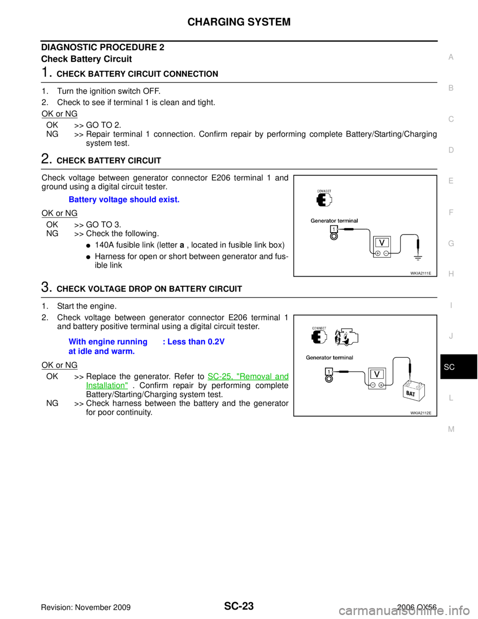
2. CHECK BATTERY CIRCUIT
Check voltage between generator connector E206 terminal 1 and
ground using a digital circuit tester.
OK or NG
OK >> GO TO 3.
NG >> Check the following.
�140A fusible link (letter a , located in fusible link box)
�Harness for open or short between generator and fus-
ible link
3. CHECK VOLTAGE DROP ON BATTERY CIRCUIT
1. Start the engine.
2. Check voltage between generator connector E206 terminal 1 and battery positive terminal using a digital circuit tester.
OK or NG
OK >> Replace the generator. Refer to SC-25, "Removal and
Installation" . Confirm repair by performing complete
Battery/Starting/Charging system test.
NG >> Check harness between the battery and the generator for poor continuity.
Battery voltage should exist.
W K I A 2 111 E
With engine running
at idle and warm.
: Less than 0.2V
WKIA2112E
Page 2929 of 3383

SC-24
CHARGING SYSTEM
Revision: November 20092006 QX56
DIAGNOSTIC PROCEDURE 3
Check Voltage Regulator Circuit
1. CHECK VOLTAGE REGULATOR CIRCUIT CONNECTION
1. Turn the ignition switch OFF.
2. Check to see if terminal 4 is clean and tight.
OK or NG
OK >> GO TO 2.
NG >> Repair terminal 4 connection. Confirm repair by performing complete Battery/Starting/Charging system test.
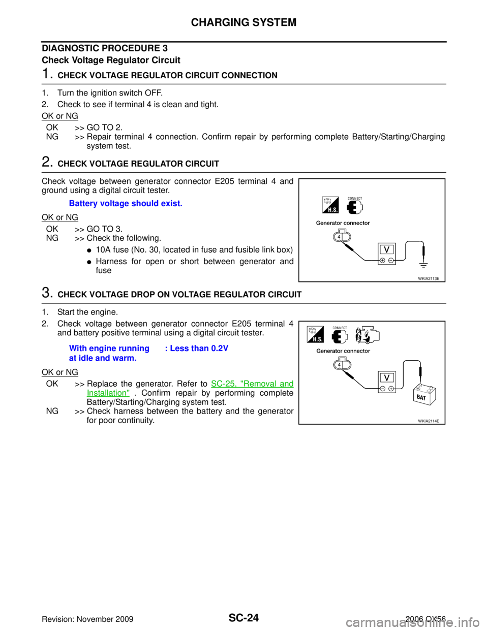
2. CHECK VOLTAGE REGULATOR CIRCUIT
Check voltage between generator connector E205 terminal 4 and
ground using a digital circuit tester.
OK or NG
OK >> GO TO 3.
NG >> Check the following.
�10A fuse (No. 30, located in fuse and fusible link box)
�Harness for open or short between generator and
fuse
3. CHECK VOLTAGE DROP ON VOLTAGE REGULATOR CIRCUIT
1. Start the engine.
2. Check voltage between generator connector E205 terminal 4 and battery positive terminal using a digital circuit tester.
OK or NG
OK >> Replace the generator. Refer to SC-25, "Removal and
Installation" . Confirm repair by performing complete
Battery/Starting/Charging system test.
NG >> Check harness between the battery and the generator for poor continuity.
Battery voltage should exist.
WKIA2113E
With engine running
at idle and warm.
: Less than 0.2V
WKIA2114E
Page 2930 of 3383
CHARGING SYSTEMSC-25
C
DE
F
G H
I
J
L
M A
B
SC
Revision: November 2009 2006 QX56
MALFUNCTION INDICATOR
The IC regulator warning function activates to illuminate “CHARGE” warning lamp, if any of the following
symptoms occur while generator is operating:
�Excessive voltage is produced.
�No voltage is produced.
Removal and InstallationEKS00B7K
REMOVAL
1. Disconnect the negative battery terminal.
2. Remove the fan shroud. Refer to CO-14, "
Removal and Installation" .
3. Remove the drive belt. Refer to EM-13, "
Removal and Installation" .
4. Remove the lower bracket, using power tools.
5. Remove the generator upper bolt, using power tools.
6. Remove/disconnect the generator harness connectors.
7. Remove the generator.
INSTALLATION
Installation is in the reverse order of removal.
�Install the generator and check the tension of the drive belt. Refer to EM-13, "DRIVE BELT TENSION" .
CAUTION:
Tighten terminal nut carefully.
WKIA1390E
Terminal nut : 10.8 N·m (1.1 kg-m, 8 ft-lb)