Page 2737 of 3383
PS-4
PREPARATION
Revision: November 20092006 QX56
Commercial Service ToolsEGS00122
KV40107300
(— ) Crimping boot bands
—
(J-44372)
Spring gauge Measuring steering wheel turning force
Tool number
(Kent-Moore No.)
Tool name
Description
ZZA1229D
LST024
Tool name
Description
Power tool Removing nuts and bolts
PBIC0190E
Page 2739 of 3383

PS-6
POWER STEERING FLUID
Revision: November 20092006 QX56
POWER STEERING FLUIDPFP:KLF20
Checking Fluid LevelEGS000U9
Check power steering fluid level with engine off, referring to the scale
on reservoir tank.
Use HOT range for fluid temperatures of 50° – 80 °C (122 ° – 176° F).
Use COLD range for fluid temperatures of 0 ° – 30° C (32 ° – 86 °F).
CAUTION:
�Do not overfill.
�Do not reuse any used power steering fluid.
�Recommended fluid is Genuine NISSAN PSF or equivalent.
Refer to MA-11, "
RECOMMENDED FLUIDS AND LUBRI-
CANTS" .
Checking Fluid LeakageEGS000UA
Check the hydraulic piping lines for improper attachment and for
leaks, cracks, damage, loose connections, chafing or deterioration.
1. Run engine until fluid temperature reaches 50 ° – 80 °C (122 ° –
176° F) in reservoir tank. Keep engine speed idle.
2. Turn steering wheel right-to-left several times.
3. Hold steering wheel at each “lock” position for five seconds to
check fluid leakage.
CAUTION:
Do not hold steering wheel in a locked position for more
than 10 seconds. (There is the possibility that oil pump may
be damaged.)
4. If fluid leakage at connections is noticed, then loosen flare nut and then retighten. Do not over tighten con- nector as this can damage O-ring, washer and connector.
5. If fluid leakage from oil pump is noticed, check oil pump. Refer to PS-21, "
POWER STEERING OIL
PUMP" .
6. Check steering gear boots for accumulation of fluid indicating a leak from the steering gear.
Air Bleeding Hydraulic SystemEGS000UB
Incomplete air bleeding causes the following. When this happens, bleed air again.
�Air bubbles in reservoir tank.
�Clicking noise in oil pump.
�Excessive buzzing in oil pump.
NOTE:
When vehicle is stationary or while steering wheel is being turned slowly, some noise may be heard from
oil pump or gear. This noise is normal and does not affect any system.
1. Stop engine, and then turn steering wheel fully to right and left several times. CAUTION:
Do not allow steering fluid reservoir tank to go below the MIN level line. Check tank frequently and
add fluid as needed.
2. Run engine at idle speed. Turn steering wheel fully right and then fully left, hold for about three seconds. Then check for fluid leakage.
3. Repeat step 2 several times at about three second intervals. CAUTION:
Do not hold steering wheel in the locked position for more than 10 seconds. (There is the possibil-
ity that oil pump may be damaged.)
4. Check for air bubbles or cloudy fluid.
5. If air bubbles or cloudiness still exists, stop engine, perform steps 2 and 3 again until air bubbles or cloud- iness does not exist.
6. Stop engine, check fluid level.
LGIA0021E
SGIA0506E
Page 2743 of 3383
PS-10
STEERING COLUMN
Revision: November 20092006 QX56
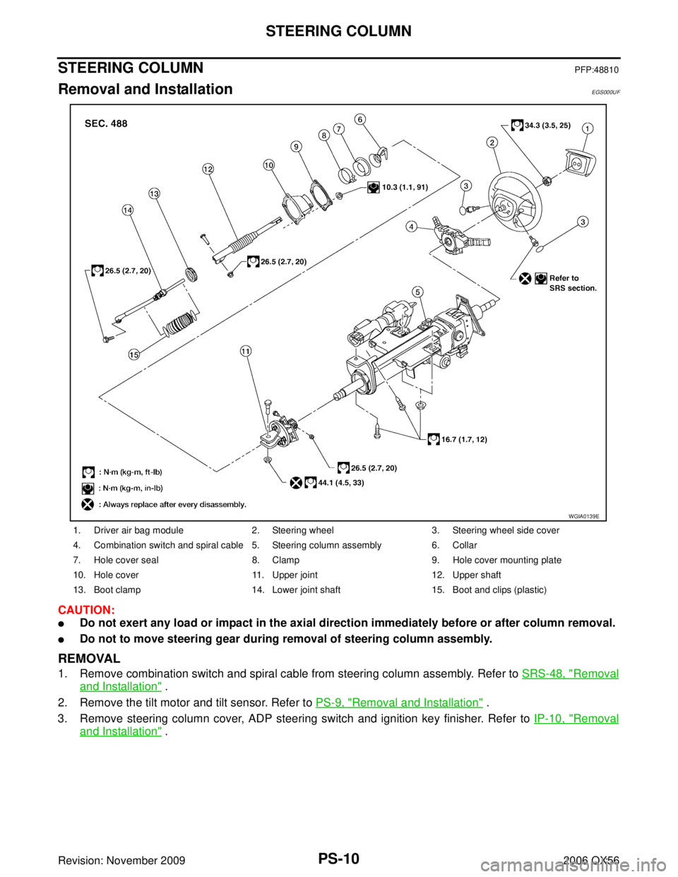
STEERING COLUMNPFP:48810
Removal and InstallationEGS000UF
CAUTION:
�Do not exert any load or impact in the axial direction immediately before or after column removal.
�Do not to move steering gear during removal of steering column assembly.
REMOVAL
1. Remove combination switch and spiral cable from steering column assembly. Refer to SRS-48, "Removal
and Installation" .
2. Remove the tilt motor and tilt sensor. Refer to PS-9, "
Removal and Installation" .
3. Remove steering column cover, ADP steering switch and ignition key finisher. Refer to IP-10, "
Removal
and Installation" .
1. Driver air bag module2. Steering wheel 3. Steering wheel side cover
4. Combination switch and spiral cable 5. Steering column assembly 6. Collar
7. Hole cover seal 8. Clamp 9. Hole cover mounting plate
10. Hole cover 11. Upper joint 12. Upper shaft
13. Boot clamp 14. Lower joint shaft 15. Boot and clips (plastic)
WGIA0139E
Page 2748 of 3383

POWER STEERING GEAR AND LINKAGEPS-15
C
DE
F
H I
J
K L
M A
B
PS
Revision: November 2009 2006 QX56
POWER STEERING GEAR AND LINKAGEPFP:49001
Removal and InstallationEGS000UH
CAUTION:
Spiral cable may snap due to steering operation if steering column is separated from steering gear
assembly. Therefore secure steering wheel to avoid turning.
REMOVAL
1. Turn wheels to the straight-ahead position.
2. Remove tires from vehicle using power tool.
3. Remove undercover using power tool.
4. On 4WD model, remove front final drive, then support drive shafts with wire. Refer to FFD-12, "
Removal
and Installation" .
5. Remove cotter pin at steering outer socket and discard, then loosen nut.
6. Remove steering outer socket from steering knuckle using Tool. Be careful not to damage ball joint boot.
CAUTION:
Temporarily tighten mounting nut to prevent damage to
threads and to prevent Tool from coming off.
7. On 2WD model, remove stabilizer bar mounting bolts and reposition stabilizer bar. Refer to FSU-12,
"Removal and Installation" .
1. Cotter pin2. Mounting bracket3. Mounting insulator
4. Steering gear assembly 5. Washer
WGIA0127E
Tool number : HT72520000 (J-25730-A)
SDIA1434E
Page 2750 of 3383

POWER STEERING GEAR AND LINKAGEPS-17
C
DE
F
H I
J
K L
M A
B
PS
Revision: November 2009 2006 QX56
INSPECTION AFTER INSTALLATION
Check if steering wheel turns smoothly when it is turned several times fully to the left and right lock positions.
Disassembly and AssemblyEGS00124
CAUTION:
�Secure steering gear assembly with a vise, using copper plates or something similar to prevent it
from being damaged. Do not grip cylinder with a vise.
�Before performing disassembly, clean steering gear assembly with kerosene. Be careful not to
bring any kerosene into contact with the discharge and return port connectors.
DISASSEMBLY
1. Remove cylinder tubes from gear housing assembly.
2. Loosen lock nuts of outer sockets, and remove outer sockets.
3. Remove boot clamps of the small diameter side and the large diameter side, then remove boot.
CAUTION:
When removing boots, be careful not to damage inner socket and gear housing assembly. If they
are damaged, change them to avoid oil leaks.
4. Remove inner sockets.
1. Boot clamp 2. Inner socket3. Boot
4. Boot clamp 5. Outer socket6. Cylinder tubes
7. Gear housing assembly 8. Connector
BGIA0008E
Page 2751 of 3383

PS-18
POWER STEERING GEAR AND LINKAGE
Revision: November 20092006 QX56
INSPECTION AFTER DISASSEMBLY
Boot
Check boot for tears, cracks and deformation. Replace if necessary.
Gear Housing Assembly
Check gear housing assembly for dents, cracks or damage. Replace as an assembly if necessary.
Outer Socket and Inner Socket
SWING TORQUE
�Measure the swing torque, using Tool. When ball stud and inner
socket start moving the measured value must be within the
specification. If the reading is outside the specification, replace
the socket.
ROTATING TORQUE
�Measure the rotating torque, using Tool. If the value is outside
the specification, replace the outer sockets.
AXIAL END PLAY
�Apply a load of 490 N (50 kg-f, 110 lb-f) to the ball stud axially.
Use a dial gauge to measure the amount of the movement that
the stud makes. If the value is outside the specification, replace
the sockets. Tool number : — (J-44372)
WGIA0131E
Item
Outer socket Inner socket
Measuring point Cotter pin hole of stud Shown as L: 83.2 mm (3.276 in)
Swing torque 0.3 − 2.9 N ·m (0.03 − 0.29 kg-m, 3 − 25 in-lb) 1.0 − 7.8 N·m (0.11 − 0.79 kg-m, 9 − 69 in-lb)
Measuring value (F) 4.84 − 46.7 N (0.50 − 4.7 kg-f, 4 - 34 lb-f) 12.1 − 93.7 N (1.3 − 9.5 kg, 9 − 69 lb)
Tool number : ST3127S000 (J-25765-A)
Rotating torque : 0.3 − 2.9 N·m (0.03 − 0.29 kg-m,
3 − 25 in-lb)
WGIA0132E
Outer socket : 0.5 mm (0.020 in) or less
Inner socket : 0.2 mm (0.008 in) or less
SGIA0057E
Page 2752 of 3383
POWER STEERING GEAR AND LINKAGEPS-19
C
DE
F
H I
J
K L
M A
B
PS
Revision: November 2009 2006 QX56
ASSEMBLY
1. Install the inner sockets.
2. Install the large-diameter side of the boots to the gear housing
assembly.
3. Install the small-diameter side of the boots to the groove of the inner sockets.
4. Install the boot clamps to the boots, as shown. CAUTION:
Do not reuse the large-diameter boot clamps.
5. Crimp the large-diameter boot clamps, using Tool.
6. Install the cylinder tubes to the gear housing assembly.
7. Install the lock nuts and outer sockets to the inner sockets.
SGIA0550E
AST139
Tool number : KV40107300 ( — )
RAC1133D
Page 2769 of 3383

RAX-8
REAR DRIVE SHAFT
Revision: November 20092006 QX56
5. Separate the drive shaft from the wheel hub and bearing assembly by lightly tapping the end with a suit-
able hammer and wood block. If it is difficult to separate, use a suitable puller.
6. Remove the drive shaft. CAUTION:
When removing the drive shaft, do not bend at an excessive angle to the drive shaft joint. Do not
excessively extend the slide joint.
INSPECTION AFTER REMOVAL
�Move the joint up and down, left and right, and in the axial direc-
tion. Check for any rough movement or significant looseness.
�Check the boot for cracks or other damage, and for any grease
leakage.
�If necessary, disassemble the drive shaft, and repair as neces-
sary.
INSTALLATION
Installation is in the reverse order of removal.
�Do not reuse the drive shaft inside flange bolts, discard after removal and use new bolts for installation.
�Do not reuse the cotter pin, discard after removal and use a new cotter pin for installation.
Disassembly and AssemblyEDS001XQ
DISASSEMBLY
Final Drive Side
1. Mount the drive shaft in a vise.CAUTION:
When mounting the drive shaft in a vise, use copper or aluminum plates between the vise and the
drive shaft.
2. Remove the boot bands.
RAA0030D
1. Plug 2. Housing3. Snap ring
4. Ball cage, steel ball, liner race assembly 5. Stopper ring 6. Boot band
7. Boot 8. Shaft9. Circlip
10. Joint sub-assembly
SDIA1488E
 Crimping boot bands
—
(J-44372)
Spring gauge Measuring steering wheel turning force
Tool number
(")