Page 2641 of 3383
PB-10
SERVICE DATA AND SPECIFICATIONS (SDS)
Revision: November 20092006 QX56
Page 2644 of 3383
PRECAUTIONSPG-3
C
DE
F
G H
I
J
L
M A
B
PG
Revision: November 2009 2006 QX56
PRECAUTIONS PFP:00011
Precautions for Supplemental Restraint System (SRS) “AIR BAG” and “SEAT
BELT PRE-TENSIONER”
EKS00BMY
The Supplemental Restraint System such as “AIR BAG” and “SEAT BELT PRE-TENSIONER ”, used along
with a front seat belt, helps to reduce the risk or severity of injury to the driver and front passenger for certain
types of collision. This system includes seat belt switch inputs and dual stage front air bag modules. The SRS
system uses the seat belt switches to determine the front air bag deployment, and may only deploy one front
air bag, depending on the severity of a collision and whether the front occupants are belted or unbelted.
Information necessary to service the system safely is included in the SRS and SB section of this Service Man-
ual.
WARNING:
�To avoid rendering the SRS inoperative, which could increase the risk of personal injury or death
in the event of a collision which would result in air bag inflation, all maintenance must be per-
formed by an authorized NISSAN/INFINITI dealer.
�Improper maintenance, including incorrect removal and installation of the SRS, can lead to per-
sonal injury caused by unintentional activation of the system. For removal of Spiral Cable and Air
Bag Module, see the SRS section.
�Do not use electrical test equipment on any circuit related to the SRS unless instructed to in this
Service Manual. SRS wiring harnesses can be identified by yellow and/or orange harnesses or
harness connectors.
Page 2720 of 3383
PR-1
PROPELLER SHAFT
D DRIVELINE/AXLE
CONTENTS
CE F
G H
I
J
K L
M
SECTION
A
B
PR
Revision: November 2009 2006 QX56
PREPARATION ......................................................
..... 2
Commercial Service Tools ................................... ..... 2
NOISE, VIBRATION, AND HARSHNESS (NVH)
TROUBLESHOOTING ........................................... ..... 3
NVH Troubleshooting Chart ................................ ..... 3
FRONT PROPELLER SHAFT ............................... ..... 4
On-Vehicle Service .............................................. ..... 4
PROPELLER SHAFT VIBRATION ................... ..... 4
INSPECTION ................................................... ..... 4
Removal and Installation ..................................... ..... 4
REMOVAL ........................................................ ..... 5
INSPECTION AFTER REMOVAL .................... ..... 5
INSTALLATION ................................................ ..... 5
Disassembly and Assembly ................................ ..... 5
DISASSEMBLY ................................................ ..... 5
ASSEMBLY ...................................................... ..... 6REAR PROPELLER SHAFT .................................
..... 8
On-Vehicle Service .............................................. ..... 8
PROPELLER SHAFT VIBRATION ................... ..... 8
INSPECTION ................................................... ..... 8
Removal and Installation ..................................... ..... 8
REMOVAL ........................................................ ..... 9
INSPECTION AFTER REMOVAL .................... ..... 9
INSTALLATION ................................................ ..... 9
Disassembly and Assembly ................................. ... 10
DISASSEMBLY ................................................ ... 10
ASSEMBLY ...................................................... ... 11
SERVICE DATA AND SPECIFICATIONS (SDS) ... ... 12
General Specifications ......................................... ... 12
Snap Ring ............................................................ ... 13
Page 2721 of 3383
PR-2
PREPARATION
Revision: November 20092006 QX56
PREPARATIONPFP:00002
Commercial Service ToolsEDS001W3
Tool nameDescription
Power tool Loosening bolts and nuts
PBIC0190E
Page 2723 of 3383
PR-4
FRONT PROPELLER SHAFT
Revision: November 20092006 QX56
FRONT PROPELLER SHAFTPFP:37200
On-Vehicle ServiceEDS001W5
PROPELLER SHAFT VIBRATION
NOTE:
If a vibration is present at high speed, inspect the propeller shaft run out first.
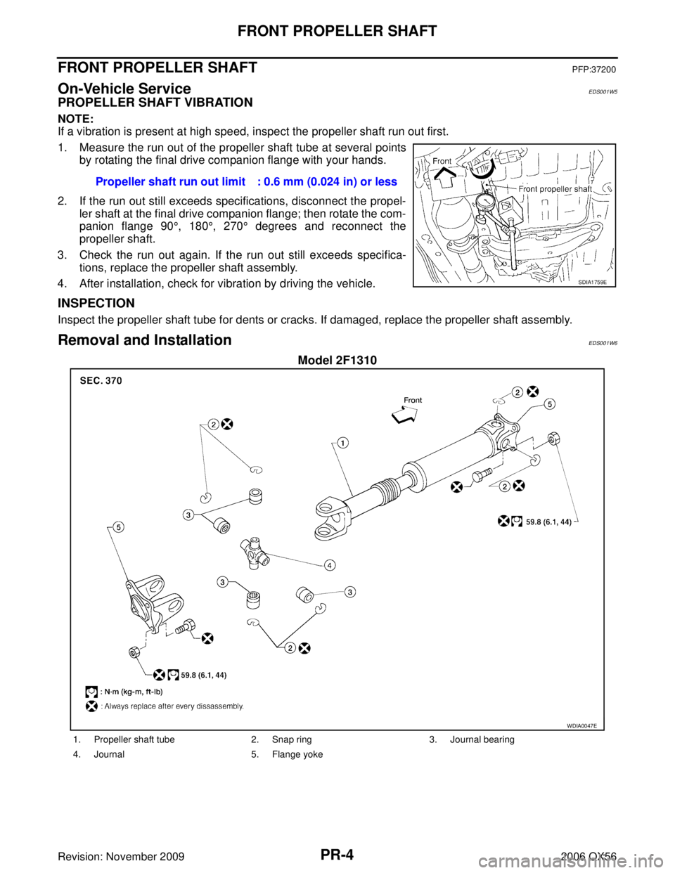
1. Measure the run out of the propeller shaft tube at several points
by rotating the final drive companion flange with your hands.
2. If the run out still exceeds specifications, disconnect the propel- ler shaft at the final drive companion flange; then rotate the com-
panion flange 90 °, 180 °, 270 ° degrees and reconnect the
propeller shaft.
3. Check the run out again. If the run out still exceeds specifica- tions, replace the propeller shaft assembly.
4. After installation, check for vibration by driving the vehicle.
INSPECTION
Inspect the propeller shaft tube for dents or cracks. If damaged, replace the propeller shaft assembly.
Removal and InstallationEDS001W6
Model 2F1310
Propeller shaft run out limit : 0.6 mm (0.024 in) or less
SDIA1759E
WDIA0047E
1. Propeller shaft tube 2. Snap ring 3. Journal bearing
4. Journal 5. Flange yoke
Page 2727 of 3383
PR-8
REAR PROPELLER SHAFT
Revision: November 20092006 QX56
REAR PROPELLER SHAFTPFP:37000
On-Vehicle ServiceEDS001W8
PROPELLER SHAFT VIBRATION
NOTE:
If vibration is present at high speed, check propeller shaft run out first, then check mounting between propeller
shaft and companion flange.
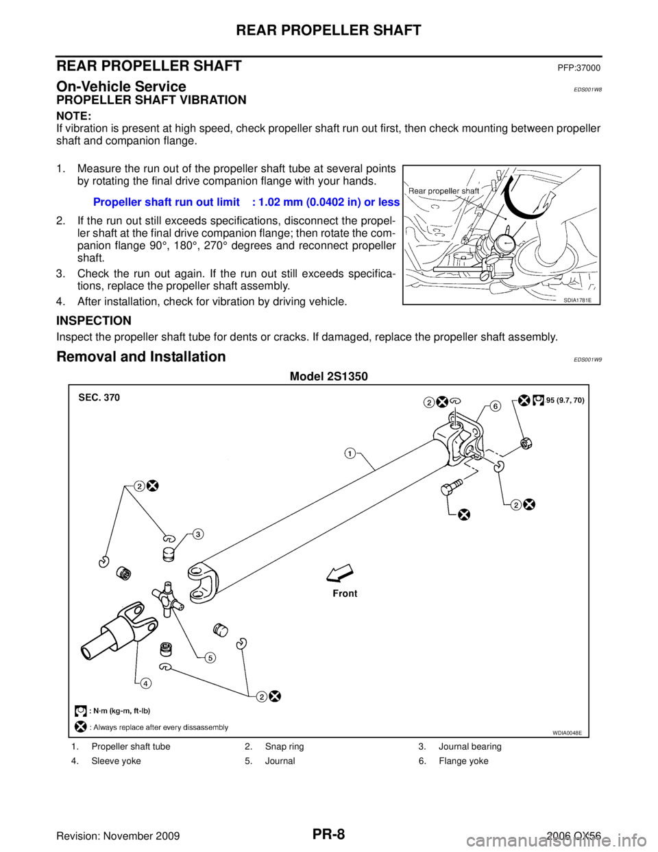
1. Measure the run out of the propeller shaft tube at several points
by rotating the final drive companion flange with your hands.
2. If the run out still exceeds specifications, disconnect the propel- ler shaft at the final drive companion flange; then rotate the com-
panion flange 90 °, 180 °, 270 ° degrees and reconnect propeller
shaft.
3. Check the run out again. If the run out still exceeds specifica- tions, replace the propeller shaft assembly.
4. After installation, check for vibration by driving vehicle.
INSPECTION
Inspect the propeller shaft tube for dents or cracks. If damaged, replace the propeller shaft assembly.
Removal and InstallationEDS001W9
Model 2S1350
Propeller shaft run out limit : 1.02 mm (0.0402 in) or less
SDIA1781E
WDIA0048E
1. Propeller shaft tube 2. Snap ring 3. Journal bearing
4. Sleeve yoke 5. Journal 6. Flange yoke
Page 2731 of 3383
PR-12
SERVICE DATA AND SPECIFICATIONS (SDS)
Revision: November 20092006 QX56
SERVICE DATA AND SPECIFICATIONS (SDS)PFP:00030
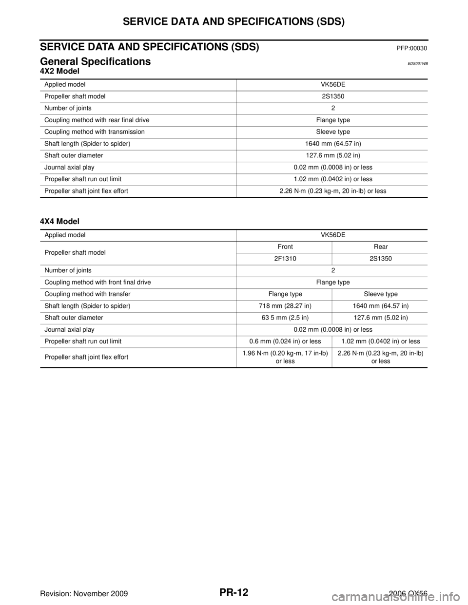
General SpecificationsEDS001WB
4X2 Model
4X4 Model
Applied modelVK56DE
Propeller shaft model 2S1350
Number of joints 2
Coupling method with rear final drive Flange type
Coupling method with transmission Sleeve type
Shaft length (Spider to spider) 1640 mm (64.57 in)
Shaft outer diameter 127.6 mm (5.02 in)
Journal axial play 0.02 mm (0.0008 in) or less
Propeller shaft run out limit 1.02 mm (0.0402 in) or less
Propeller shaft joint flex effort 2.26 N·m (0.23 kg-m, 20 in-lb) or less
Applied model VK56DE
Propeller shaft model Front
Rear
2F1310 2S1350
Number of joints 2
Coupling method with front final drive Flange type
Coupling method with transfer Flange typeSleeve type
Shaft length (Spider to spider) 718 mm (28.27 in)1640 mm (64.57 in)
Shaft outer diameter 63 5 mm (2.5 in)127.6 mm (5.02 in)
Journal axial play 0.02 mm (0.0008 in) or less
Propeller shaft run out limit 0.6 mm (0.024 in) or less 1.02 mm (0.0402 in) or less
Propeller shaft joint flex effort 1.96 N·m (0.20 kg-m, 17 in-lb)
or less 2.26 N·m (0.23 kg-m, 20 in-lb)
or less
Page 2732 of 3383
SERVICE DATA AND SPECIFICATIONS (SDS)PR-13
CE F
G H
I
J
K L
M A
B
PR
Revision: November 2009 2006 QX56
Snap RingEDS001WC
Model 2F1310
Unit: mm (in)
*Always check with the Parts Department for the latest parts information.
Model 2S1350
Unit: mm (in)
*Always check with the Parts Department for the latest parts information. Thickness
ColorPart Number*
1.99 (0.0783) White37146-C9400
2.02 (0.0795) Yellow37147-C9400
2.05 (0.0807) Red37148-C9400
2.08 (0.0819) Green37149-C9400
2.11 (0.0831) Blue37150-C9400
2.14 (0.0843) Light brown 37151-C9400
2.17 (0.0854) Black37152-C9400
2.20 (0.0866) No paint37153-C9400
Thickness ColorPart Number*
1.600 - 1.638 (0.0630 - 0.0645) Black37146-7S000
1.549 - 1.588 (0.0610 - 0.0625) Black37147-7S000
1.524 - 1.562 (0.0600 - 0.0615) Black37148-7S000
1.499 - 1.537 (0.0590 - 0.0605) Black37149-7S000