Page 3090 of 3383

SPIRAL CABLESRS-49
C
DE
F
G
I
J
K L
M A
B
SRS
Revision: November 2009 2006 QX56
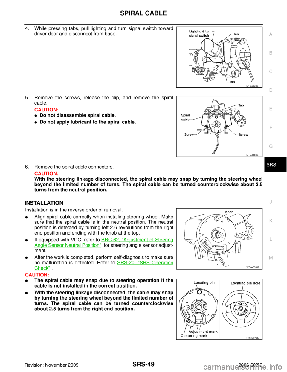
4. While pressing tabs, pull lighting and turn signal switch toward
driver door and disconnect from base.
5. Remove the screws, release the clip, and remove the spiral cable.
CAUTION:
�Do not disassemble spiral cable.
�Do not apply lubricant to the spiral cable.
6. Remove the spiral cable connectors. CAUTION:
With the steering linkage disconnected, the spiral cable may snap by turning the steering wheel
beyond the limited number of turns. The spiral cable can be turned counterclockwise about 2.5
turns from the neutral position.
INSTALLATION
Installation is in the reverse order of removal.
�Align spiral cable correctly when installing steering wheel. Make
sure that the spiral cable is in the neutral position. The neutral
position is detected by turning left 2.6 revolutions from the right
end position and ending with the knob at the top.
�If equipped with VDC, refer to BRC-62, "Adjustment of Steering
Angle Sensor Neutral Position" for steering angle sensor adjust-
ment.
�After the work is completed, perform self-diagnosis to make sure
no malfunction is detected. Refer to SRS-20, "
SRS Operation
Check" .
CAUTION:
�The spiral cable may snap due to steering operation if the
cable is not installed in the correct position.
�With the steering linkage disconnected, the cable may snap
by turning the steering wheel beyond the limited number of
turns. The spiral cable can be turned counterclockwise
about 2.5 turns from the right end position.
LHIA0035E
LHIA0036E
WGIA0038E
PHIA0275E
Page 3365 of 3383

WW-38
REAR WIPER AND WASHER SYSTEM
Revision: November 20092006 QX56
Terminals and Reference Values for BCMEKS00BEE
Te r m i -
nal No. Wire
color Signal name Measuring condition
Reference Value (V)
(Approx.)
Ignition
switch Operation or condition
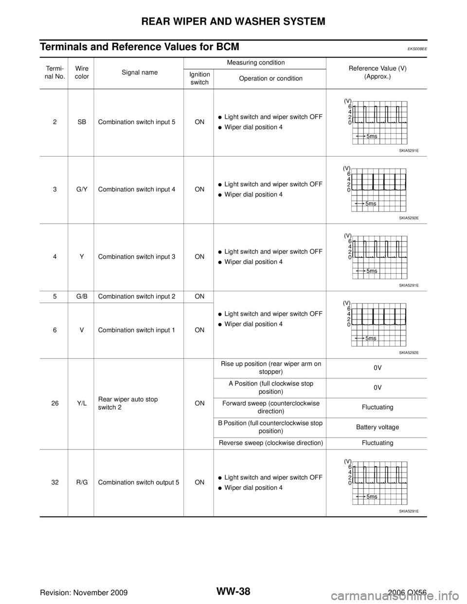
2 SB Combination switch input 5 ON
�Light switch and wiper switch OFF
�Wiper dial position 4
3 G/Y Combination switch input 4 ON
�Light switch and wiper switch OFF
�Wiper dial position 4
4 Y Combination switch input 3 ON
�Light switch and wiper switch OFF
�Wiper dial position 4
5 G/B Combination switch input 2 ON
�Light switch and wiper switch OFF
�Wiper dial position 4
6 V Combination switch input 1 ON
26 Y/L Rear wiper auto stop
switch 2
ONRise up position (rear wiper arm on
stopper) 0V
A Position (full clockwise stop position) 0V
Forward sweep (counterclockwise direction) Fluctuating
B Position (full counterclockwise stop position) Battery voltage
Reverse sweep (clockwise direction) Fluctuating
32 R/G Combination switch output 5 ON
�Light switch and wiper switch OFF
�Wiper dial position 4
SKIA5291E
SKIA5292E
SKIA5291E
SKIA5292E
SKIA5291E
Page 3366 of 3383

REAR WIPER AND WASHER SYSTEMWW-39
C
DE
F
G H
I
J
L
M A
B
WW
Revision: November 2009 2006 QX56
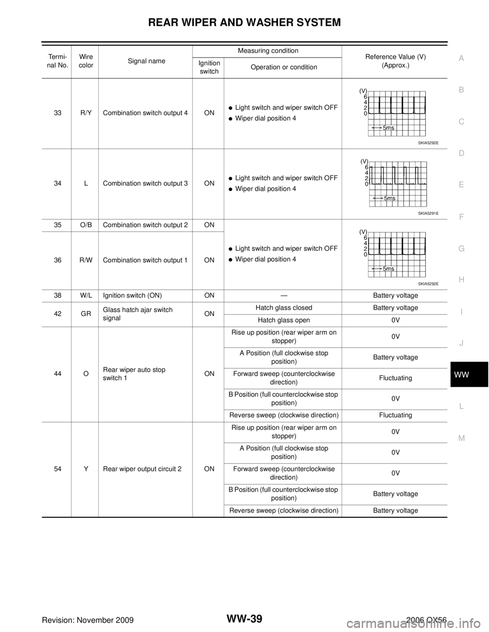
33 R/Y Combination switch output 4 ON�Light switch and wiper switch OFF
�Wiper dial position 4
34 L Combination switch output 3 ON
�Light switch and wiper switch OFF
�Wiper dial position 4
35 O/B Combination switch output 2 ON
�Light switch and wiper switch OFF
�Wiper dial position 4
36 R/W Combination switch output 1 ON
38 W/L Ignition switch (ON) ON— Battery voltage
42 GR Glass hatch ajar switch
signal ONHatch glass closed
Battery voltage
Hatch glass open 0V
44 O Rear wiper auto stop
switch 1 ONRise up position (rear wiper arm on
stopper) 0V
A Position (full clockwise stop position) Battery voltage
Forward sweep (counterclockwise direction) Fluctuating
B Position (full counterclockwise stop position) 0V
Reverse sweep (clockwise direction) Fluctuating
54 Y Rear wiper output circuit 2 ON Rise up position (rear wiper arm on
stopper) 0V
A Position (full clockwise stop position) 0V
Forward sweep (counterclockwise direction) 0V
B Position (full counterclockwise stop position) Battery voltage
Reverse sweep (clockwise direction) Battery voltage
Te r m i -
nal No. Wire
color Signal name Measuring condition
Reference Value (V)
(Approx.)
Ignition
switch Operation or condition
SKIA5292E
SKIA5291E
SKIA5292E
Page 3381 of 3383
WW-54
POWER SOCKET
Revision: November 20092006 QX56
Front Power Socket LH, Rear Cargo Power SocketEKS00BEX
REMOVAL AND INSTALLATION
Removal
1. Disconnect battery negative terminal.
2. Remove inner socket from the ring, while pressing the hook on
the ring out from square hole.
3. Disconnect power socket connector.
4. Remove ring from power socket finisher while pressing pawls.
INSTALLATION
Installation is in the reverse order of removal.
Front Power Socket RH (For Cigarette Lighter), Console Power SocketEKS00GBK
REMOVAL
1. Remove inner socket from the ring, while pressing the hook on the ring out from square hole.
2. Disconnect power socket connector.
3. Remove ring from power socket finisher while pressing pawls.
INSTALLATION
Installation is in the reverse order of removal.
WKIA1035E
WKIA1035E
Page:
< prev 1-8 9-16 17-24