Page 2497 of 3383
LT-90
TURN SIGNAL AND HAZARD WARNING LAMPS
Revision: November 20092006 QX56
CONSULT-II Function (BCM)EKS00B9W
CONSULT-II can display each diagnostic item using the diagnostic test modes shown following.
CONSULT-II OPERATION
CAUTION:
If CONSULT-II is used with no connection of CONSULT-II CONVERTER, malfunctions might be
detected in self-diagnosis depending on control unit which carries out CAN communication.
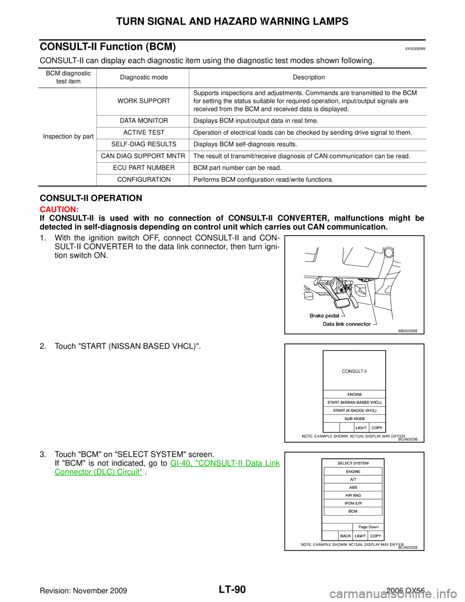
1. With the ignition switch OFF, connect CONSULT-II and CON-
SULT-II CONVERTER to the data link connector, then turn igni-
tion switch ON.
2. Touch "START (NISSAN BASED VHCL)".
3. Touch "BCM" on "SELECT SYSTEM" screen. If "BCM" is not indicated, go to GI-40, "
CONSULT-II Data Link
Connector (DLC) Circuit" .
BCM diagnostic
test item Diagnostic mode
Description
Inspection by part WORK SUPPORT
Supports inspections and adjustments. Commands are transmitted to the BCM
for setting the status suitable for required operation, input/output signals are
received from the BCM and received data is displayed.
DATA MONITOR Displays BCM input/output data in real time. ACTIVE TEST Operation of electrical loads can be checked by sending drive signal to them.
SELF-DIAG RESULTS Displays BCM self-diagnosis results.
CAN DIAG SUPPORT MNTR The result of transmit/receive diagnosis of CAN communication can be read. ECU PART NUMBER BCM part number can be read.CONFIGURATION Performs BCM configuration read/write functions.
BBIA0369E
BCIA0029E
BCIA0030E
Page 2498 of 3383
TURN SIGNAL AND HAZARD WARNING LAMPSLT-91
C
DE
F
G H
I
J
L
M A
B
LT
Revision: November 2009 2006 QX56
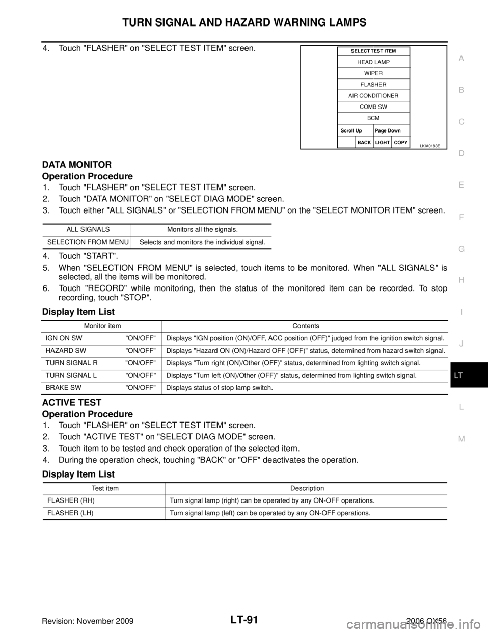
4. Touch "FLASHER" on "SELECT TEST ITEM" screen.
DATA MONITOR
Operation Procedure
1. Touch "FLASHER" on "SELECT TEST ITEM" screen.
2. Touch "DATA MONITOR" on "SELECT DIAG MODE" screen.
3. Touch either "ALL SIGNALS" or "SELECTION FROM MENU" on the "SELECT MONITOR ITEM" screen.
4. Touch "START".
5. When "SELECTION FROM MENU" is selected, touch items to be monitored. When "ALL SIGNALS" is
selected, all the items will be monitored.
6. Touch "RECORD" while monitoring, then the status of the monitored item can be recorded. To stop recording, touch "STOP".
Display Item List
ACTIVE TEST
Operation Procedure
1. Touch "FLASHER" on "SELECT TEST ITEM" screen.
2. Touch "ACTIVE TEST" on "SELECT DIAG MODE" screen.
3. Touch item to be tested and check operation of the selected item.
4. During the operation check, touching "BACK" or "OFF" deactivates the operation.
Display Item List
LKIA0183E
ALL SIGNALS Monitors all the signals.
SELECTION FROM MENU Selects and monitors the individual signal.
Monitor item Contents
IGN ON SW "ON/OFF" Displays "IGN position (ON)/OFF, ACC position (OFF)" judged from the ignition switch signal.
HAZARD SW "ON/OFF" Displays "Hazard ON (ON)/Hazard OFF (OFF)" status, determined from hazard switch signal.
TURN SIGNAL R "ON/OFF" Displays "Turn right (ON)/Other (OFF)" status, determined from lighting switch signal.
TURN SIGNAL L "ON/OFF" Displays "Turn left (ON)/Other (OFF)" status, determined from lighting switch signal.
BRAKE SW "ON/OFF" Displays status of stop lamp switch.
Test item Description
FLASHER (RH) Turn signal lamp (right) can be operated by any ON-OFF operations.
FLASHER (LH) Turn signal lamp (left) can be operated by any ON-OFF operations.
Page 2499 of 3383
LT-92
TURN SIGNAL AND HAZARD WARNING LAMPS
Revision: November 20092006 QX56
Front Turn Signal Lamp Does Not OperateEKS00B9X
1. CHECK COMBINATION SWITCH INPUT SIGNAL
With CONSULT-II
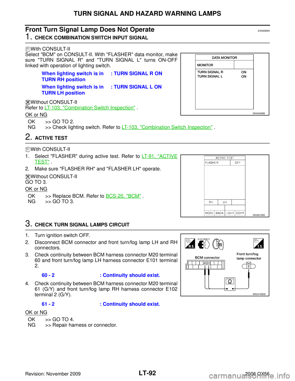
Select "BCM" on CONSULT-II. With "FLASHER" data monitor, make
sure "TURN SIGNAL R" and "TURN SIGNAL L" turns ON-OFF
linked with operation of lighting switch.
Without CONSULT-II
Refer to LT- 1 0 3 , "
Combination Switch Inspection" .
OK or NG
OK >> GO TO 2.
NG >> Check lighting switch. Refer to LT- 1 0 3 , "
Combination Switch Inspection" .
2. ACTIVE TEST
With CONSULT-II
1. Select "FLASHER" during active test. Refer to LT- 9 1 , "
ACTIVE
TEST" .
2. Make sure "FLASHER RH" and "FLASHER LH" operate.
Without CONSULT-II
GO TO 3.
OK or NG
OK >> Replace BCM. Refer to BCS-20, "BCM" .
NG >> GO TO 3.
3. CHECK TURN SIGNAL LAMPS CIRCUIT
1. Turn ignition switch OFF.
2. Disconnect BCM connector and front turn/fog lamp LH and RH connectors.
3. Check continuity between BCM harness connector M20 terminal 60 and front turn/fog lamp LH harness connector E101 terminal
2.
4. Check continuity between BCM harness connector M20 terminal 61 (G/Y) and front turn/fog lamp RH harness connector E102
terminal 2 (G/Y).
OK or NG
OK >> GO TO 4.
NG >> Repair harness or connector. When lighting switch is in
TURN RH position
: TURN SIGNAL R ON
When lighting switch is in
TURN LH position : TURN SIGNAL L ON
SKIA4499E
SKIA6190E
60 - 2
: Continuity should exist.
61 - 2 : Continuity should exist.
WKIA1890E
Page 2500 of 3383
TURN SIGNAL AND HAZARD WARNING LAMPSLT-93
C
DE
F
G H
I
J
L
M A
B
LT
Revision: November 2009 2006 QX56
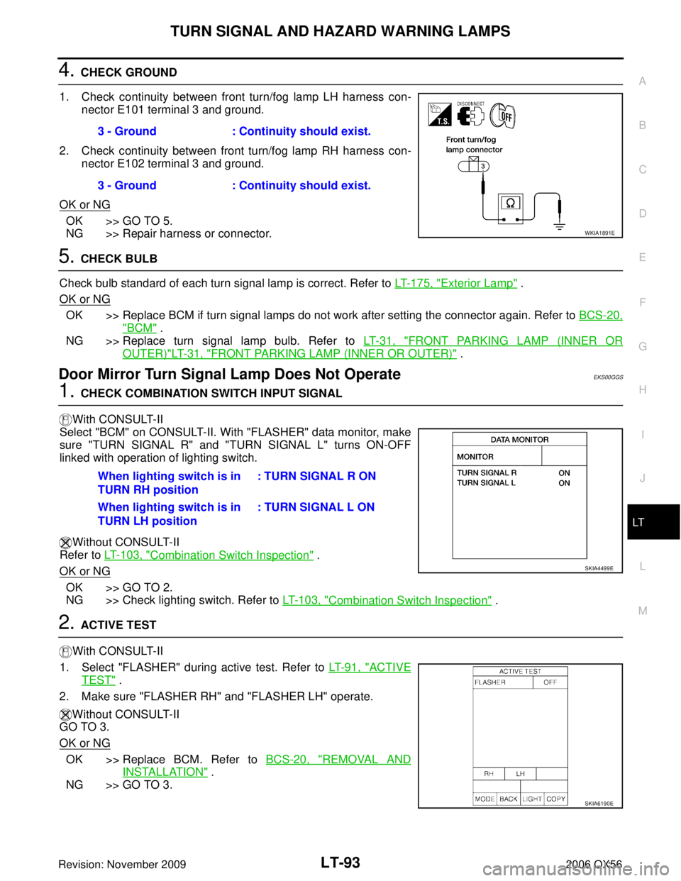
4. CHECK GROUND
1. Check continuity between front turn/fog lamp LH harness con- nector E101 terminal 3 and ground.
2. Check continuity between front turn/fog lamp RH harness con- nector E102 terminal 3 and ground.
OK or NG
OK >> GO TO 5.
NG >> Repair harness or connector.
5. CHECK BULB
Check bulb standard of each turn signal lamp is correct. Refer to LT- 1 7 5 , "
Exterior Lamp" .
OK or NG
OK >> Replace BCM if turn signal lamps do not work after setting the connector again. Refer to BCS-20,
"BCM" .
NG >> Replace turn signal lamp bulb. Refer to LT- 3 1 , "
FRONT PARKING LAMP (INNER OR
OUTER)"LT- 3 1 , "FRONT PARKING LAMP (INNER OR OUTER)" .
Door Mirror Turn Signal Lamp Does Not OperateEKS00GGS
1. CHECK COMBINATION SWITCH INPUT SIGNAL
With CONSULT-II
Select "BCM" on CONSULT-II. With "FLASHER" data monitor, make
sure "TURN SIGNAL R" and "TURN SIGNAL L" turns ON-OFF
linked with operation of lighting switch.
Without CONSULT-II
Refer to LT- 1 0 3 , "
Combination Switch Inspection" .
OK or NG
OK >> GO TO 2.
NG >> Check lighting switch. Refer to LT- 1 0 3 , "
Combination Switch Inspection" .
2. ACTIVE TEST
With CONSULT-II
1. Select "FLASHER" during active test. Refer to LT- 9 1 , "
ACTIVE
TEST" .
2. Make sure "FLASHER RH" and "FLASHER LH" operate.
Without CONSULT-II
GO TO 3.
OK or NG
OK >> Replace BCM. Refer to BCS-20, "REMOVAL AND
INSTALLATION" .
NG >> GO TO 3. 3 - Ground
: Continuity should exist.
3 - Ground : Continuity should exist.
WKIA1891E
When lighting switch is in
TURN RH position : TURN SIGNAL R ON
When lighting switch is in
TURN LH position : TURN SIGNAL L ON
SKIA4499E
SKIA6190E
Page 2501 of 3383
LT-94
TURN SIGNAL AND HAZARD WARNING LAMPS
Revision: November 20092006 QX56
3. CHECK TURN SIGNAL LAMPS CIRCUIT
1. Turn ignition switch OFF.
2. Disconnect BCM connector and door mirror LH/RH connector.
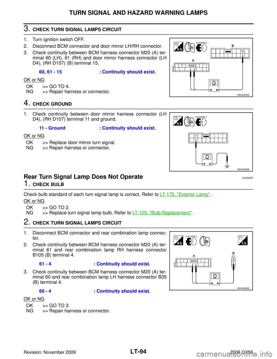
3. Check continuity between BCM harness connector M20 (A) ter- minal 60 (LH), 61 (RH) and door mirror harness connector (LH
D4), (RH D107) (B) terminal 15.
OK or NG
OK >> GO TO 4.
NG >> Repair harness or connector.
4. CHECK GROUND
1. Check continuity between door mirror harness connector (LH D4), (RH D107) terminal 11 and ground.
OK or NG
OK >> Replace door mirror turn signal.
NG >> Repair harness or connector.
Rear Turn Signal Lamp Does Not OperateEKS00B9Y
1. CHECK BULB
Check bulb standard of each turn signal lamp is correct. Refer to LT- 1 7 5 , "
Exterior Lamp" .
OK or NG
OK >> GO TO 2.
NG >> Replace turn signal lamp bulb. Refer to LT- 1 2 5 , "
Bulb Replacement" .
2. CHECK TURN SIGNAL LAMPS CIRCUIT
1. Disconnect BCM connector and rear combination lamp connec- tor.
2. Check continuity between BCM harness connector M20 (A) ter- minal 61 and rear combination lamp RH harness connector
B105 (B) terminal 4.
3. Check continuity between BCM harness connector M20 (A) ter- minal 60 and rear combination lamp LH harness connector B35
(B) terminal 4.
OK or NG
OK >> GO TO 3.
NG >> Repair harness or connector. 60, 61 - 15
: Continuity should exist.
WKIA4524E
11 - Ground: Continuity should exist.
WKIA4525E
61 - 4: Continuity should exist.
60 - 4 : Continuity should exist.
WKIA4694E
Page 2502 of 3383
TURN SIGNAL AND HAZARD WARNING LAMPSLT-95
C
DE
F
G H
I
J
L
M A
B
LT
Revision: November 2009 2006 QX56
3. CHECK GROUND CIRCUIT
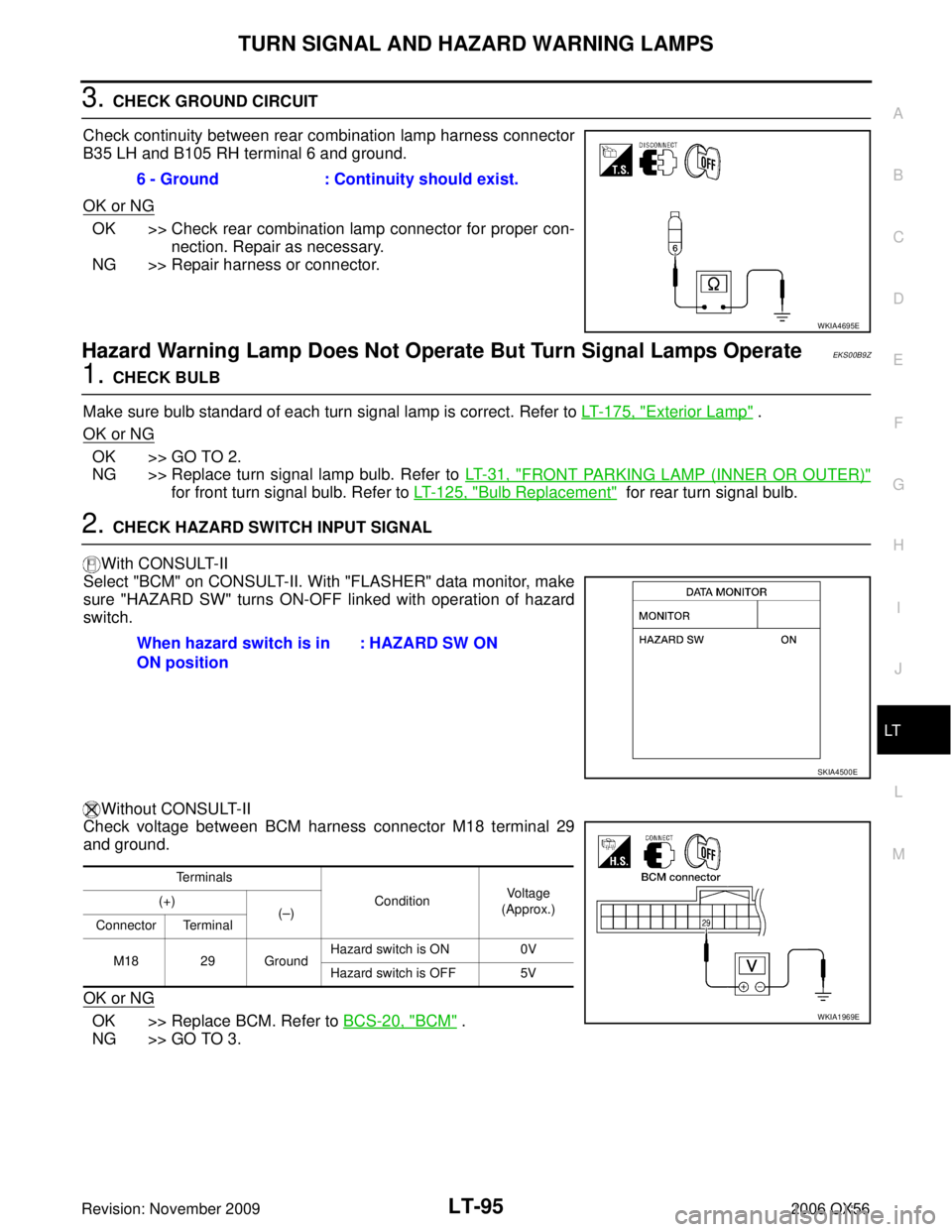
Check continuity between rear combination lamp harness connector
B35 LH and B105 RH terminal 6 and ground.
OK or NG
OK >> Check rear combination lamp connector for proper con- nection. Repair as necessary.
NG >> Repair harness or connector.
Hazard Warning Lamp Does Not Operate But Turn Signal Lamps OperateEKS00B9Z
1. CHECK BULB
Make sure bulb standard of each turn signal lamp is correct. Refer to LT- 1 7 5 , "
Exterior Lamp" .
OK or NG
OK >> GO TO 2.
NG >> Replace turn signal lamp bulb. Refer to LT- 3 1 , "
FRONT PARKING LAMP (INNER OR OUTER)"
for front turn signal bulb. Refer to LT- 1 2 5 , "Bulb Replacement" for rear turn signal bulb.
2. CHECK HAZARD SWITCH INPUT SIGNAL
With CONSULT-II
Select "BCM" on CONSULT-II. With "FLASHER" data monitor, make
sure "HAZARD SW" turns ON-OFF linked with operation of hazard
switch.
Without CONSULT-II
Check voltage between BCM harness connector M18 terminal 29
and ground.
OK or NG
OK >> Replace BCM. Refer to BCS-20, "BCM" .
NG >> GO TO 3. 6 - Ground : Continuity should exist.
WKIA4695E
When hazard switch is in
ON position
: HAZARD SW ON
SKIA4500E
Terminals
ConditionVo l ta g e
(Approx.)
(+)
(– )
Connector Terminal
M18 29 Ground Hazard switch is ON
0V
Hazard switch is OFF 5V
WKIA1969E
Page 2503 of 3383
LT-96
TURN SIGNAL AND HAZARD WARNING LAMPS
Revision: November 20092006 QX56
3. CHECK HAZARD SWITCH CIRCUIT
1. Turn ignition switch OFF.
2. Disconnect BCM connector and hazard switch connector.
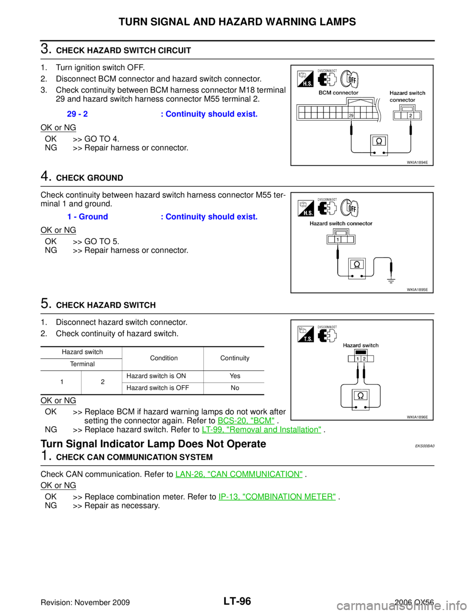
3. Check continuity between BCM harness connector M18 terminal 29 and hazard switch harness connector M55 terminal 2.
OK or NG
OK >> GO TO 4.
NG >> Repair harness or connector.
4. CHECK GROUND
Check continuity between hazard switch harness connector M55 ter-
minal 1 and ground.
OK or NG
OK >> GO TO 5.
NG >> Repair harness or connector.
5. CHECK HAZARD SWITCH
1. Disconnect hazard switch connector.
2. Check continuity of hazard switch.
OK or NG
OK >> Replace BCM if hazard warning lamps do not work after setting the connector again. Refer to BCS-20, "
BCM" .
NG >> Replace hazard switch. Refer to LT- 9 9 , "
Removal and Installation" .
Turn Signal Indicator Lamp Does Not OperateEKS00BA0
1. CHECK CAN COMMUNICATION SYSTEM
Check CAN communication. Refer to LAN-26, "
CAN COMMUNICATION" .
OK or NG
OK >> Replace combination meter. Refer to IP-13, "COMBINATION METER" .
NG >> Repair as necessary. 29 - 2 : Continuity should exist.
WKIA1894E
1 - Ground
: Continuity should exist.
WKIA1895E
Hazard switch
ConditionContinuity
Terminal
12 Hazard switch is ON
Yes
Hazard switch is OFF No
WKIA1896E
Page 2504 of 3383
TURN SIGNAL AND HAZARD WARNING LAMPSLT-97
C
DE
F
G H
I
J
L
M A
B
LT
Revision: November 2009 2006 QX56
Bulb ReplacementEKS00BA1
TURN SIGNAL LAMP (FRONT)
Removal
1. Remove front fog lamp. Refer to LT- 7 9 , "Removal and Installation" .
2. Twist turn signal socket and remove from front fog lamp.
3. Remove turn signal bulb from socket.
Installation
Installation is in the reverse order of removal.
TURN SIGNAL LAMP (REAR)
Refer to LT- 1 2 5 , "Bulb Replacement" .
Removal and InstallationEKS00BA3
FRONT TURN SIGNAL LAMP
Refer to LT- 7 9 , "Removal and Installation" .
REAR TURN SIGNAL LAMP
Refer to LT- 1 2 5 , "Removal and Installation" .