Page 675 of 3383

AV-82
DVD ENTERTAINMENT SYSTEM
Revision: November 20092006 QX56
Power Supply Circuit InspectionEKS00BJA
1. CHECK FUSES
Check that the following fuses are not blown.
OK or NG
OK >> GO TO 2.
NG >> If fuse is blown, be sure to eliminate cause of problem before installing new fuse. Refer to PG-4,
"POWER SUPPLY ROUTING CIRCUIT" .
2. POWER SUPPLY CIRCUIT CHECK
1. Disconnect DVD player connector M205.
2. Check voltage between the DVD player and ground.
OK or NG
OK >> GO TO 3.
NG >>
�Check connector housings for disconnected or loose terminals.
�Repair harness or connector.
3. GROUND CIRCUIT CHECK
Check continuity between DVD player harness connector M206 ter-
minal 22 (B) and ground.
OK or NG
OK >> Inspection End.
NG >>
�Check connector housings for disconnected or loose
terminals.
�Repair harness or connector.
Unit Terminals Signal name Fuse No.
DVD player 16
Battery power 31
15 Ignition switch ACC or ON 4
UnitTerminal No.
OFF ACC ON
(+)
(-)
Connector Te r m i n a l
(wire color)
DVD player M205 16 (Y) Ground
Battery
voltage Battery
voltage Battery
voltage
15 (V) Ground 0 V Battery
voltage Battery
voltage
WKIA1197E
Continuity should exist.
WKIA1198E
Page 719 of 3383

AV-126
NAVIGATION SYSTEM
Revision: November 20092006 QX56
Power Supply and Ground Circuit Check for NAVI Control UnitEKS00GE4
1. CHECK FUSE
Make sure the following fuses of the NAVI control unit are not blown.
OK or NG
OK >> GO TO 2.
NG >> If fuse is blown, be sure to eliminate cause of malfunction before installing new fuse. Refer to PG-
4, "POWER SUPPLY ROUTING CIRCUIT" .
2. CHECK POWER SUPPLY CIRCUIT
1. Disconnect NAVI control unit connector B151.
2. Check voltage between connector terminals and ground as fol- lows.
OK or NG
OK >> GO TO 3.
NG >> Check harness for open between NAVI control unit and fuse.
3. CHECK GROUND CIRCUIT
1. Turn ignition switch OFF.
2. Check continuity between the following NAVI control unit con- nector terminals and ground.
OK or NG
OK >> Inspection End.
NG >> Repair or replace harness.
Terminals Power source Fuse No.
Connector Terminal
B151 2
Battery power 31
5 ACC/ON power 4
TerminalsIgnition switch position
(+) (– )OFFACCON
Connector Terminal
B151 2
Ground Battery
voltage Battery
voltage Battery
voltage
50 VBattery
voltage Battery
voltage
WKIA4601E
Terminals Ignition switch Continuity
Connector Terminal—
B151 1Ground OFF Yes
WKIA4207E
Page 720 of 3383

NAVIGATION SYSTEMAV-127
C
DE
F
G H
I
J
L
M A
B
AV
Revision: November 2009 2006 QX56
Power Supply and Ground Circuit Check for Display Control UnitEKS00GE5
1. CHECK FUSE
Make sure the following fuses of the display control unit are not blown.
OK or NG
OK >> GO TO 2.
NG >> If fuse is blown, be sure to eliminate cause of malfunction before installing new fuse. Refer to PG-
4, "POWER SUPPLY ROUTING CIRCUIT" .
2. CHECK POWER SUPPLY CIRCUIT
1. Disconnect display control unit connector M94.
2. Check voltage between connector terminals and ground as fol- lows.
OK or NG
OK >> GO TO 3.
NG >> Check harness for open between display control unit and fuse.
3. CHECK GROUND CIRCUIT
Check continuity between the following display control unit connec-
tor terminals and ground.
OK or NG
OK >> Inspection End.
NG >> Repair or replace harness.
Terminals Power source Fuse No.
Connector Terminal
M94 1
Battery power 31
10 ACC power4
Terminals Ignition switch position
(+) (– )OFFACC ON
Connector Terminal
M94 1
Ground Battery
voltage Battery
voltage Battery
voltage
10 0VBattery
voltage Battery
voltage
WKIA1373E
Terminals Ignition switch Continuity
Connector Terminal—
M94 3Ground OFF Yes
SKIA4293E
Page 723 of 3383

AV-130
NAVIGATION SYSTEM
Revision: November 20092006 QX56
Power Supply and Ground Circuit Check for AV SwitchEKS00GE7
1. CHECK FUSE
Make sure the following fuses of the AV switch are not blown.
OK or NG
OK >> GO TO 2.
NG >> If fuse is blown, be sure to eliminate cause of malfunction before installing new fuse. Refer to PG-
4, "POWER SUPPLY ROUTING CIRCUIT" .
2. CHECK POWER SUPPLY CIRCUIT
1. Disconnect AV switch connector.
2. Check voltage between connector terminals and ground as fol- lows.
OK or NG
OK >> GO TO 3.
NG >> Check harness for open between AV switch and fuse.
3. CHECK GROUND CIRCUIT
Check continuity between AV switch and ground as follows.
OK or NG
OK >> Inspection End.
NG >> Repair or replace harness.
Terminals Power source Fuse No.
Connector Terminal
M98 1
Battery power 31
2 ACC power4
Terminals Ignition switch position
(+) (– )OFFACCON
Connector Terminal
M98 1
GroundBattery
voltage Battery
voltage Battery
voltage
20 VBattery
voltage Battery
voltage
WKIA1767E
Terminals Ignition switch Continuity
Connector Terminal—
M98 5Ground OFF Yes
WKIA1768E
Page 840 of 3383

REMOTE KEYLESS ENTRY SYSTEMBL-59
C
DE
F
G H
J
K L
M A
B
BL
Revision: November 2009 2006 QX56
Trouble Diagnosis ProcedureEIS005ZZ
1. Check the symptom and customer's requests.
2. Understand outline of system. Refer to BL-45, "
System Description" .
3. Confirm system operation.
�Check that the power door lock system operates normally. Refer to BL-16, "POWER DOOR LOCK
SYSTEM" .
�Check that the automatic back door system operates normally. Refer to BL-99, "AUTOMATIC BACK
DOOR SYSTEM" .
4. Perform pre-diagnosis inspection. Refer to BL-59, "
BCM Power Supply and Ground Circuit Check" .
5. Refer to trouble diagnosis chart by symptom, repair or replace any malfunctioning parts. Refer to BL-60,
"Trouble Diagnoses" .
6. Inspection End.
BCM Power Supply and Ground Circuit CheckEIS00600
1. CHECK FUSE AND FUSIBLE LINK
Check the following BCM fuses and fusible link.
NOTE:
Refer to BL-44, "
Component Parts and Harness Connector Location" .
OK or NG
OK >> GO TO 2.
NG >> If fuse is blown, be sure to eliminate cause of problem before installing new fuse, refer to PG-4,
"POWER SUPPLY ROUTING CIRCUIT" .
2. CHECK POWER SUPPLY CIRCUIT
1. Turn ignition switch OFF.
2. Disconnect BCM.
3. Check voltage between BCM connectors M18, M20 terminals 11, 38, 57, 70 and ground.
OK or NG
OK >> GO TO 3.
NG >> Repair or replace harness.
Component Parts Terminal No. (SIGNAL) AmpereNo. Location
BCM 57 (BAT power supply)
15A22 Fuse block (J/B)
70 (BAT power supply) 50AfFuse and fusible link box
11 (ACC power supply) 10A4 Fuse block (J/B)
38 (IGN power supply) 10A59 Fuse and relay box
ConnectorTerminals
Signal nameIgnition
switch Vo l ta g e
(+) ( –)
M20 70
Ground Battery power
supply OFFBattery
voltage
57 Battery power
supply OFFBattery
voltage
M18 11
ACC power
supply ACC
Battery
voltage
38 IGN power
supply ONBattery
voltage
WIIA0600E
Page 1087 of 3383
![INFINITI QX56 2006 Factory Service Manual BRC-60
[VDC/TCS/ABS]
TROUBLE DIAGNOSES FOR SYMPTOMS
Revision: November 20092006 QX56
ABS Warning Lamp Does Not Come On When Ignition Switch Is Turned OnEFS004YE
1. CHECK ABS ACTUATOR AND ELECTRIC UNIT INFINITI QX56 2006 Factory Service Manual BRC-60
[VDC/TCS/ABS]
TROUBLE DIAGNOSES FOR SYMPTOMS
Revision: November 20092006 QX56
ABS Warning Lamp Does Not Come On When Ignition Switch Is Turned OnEFS004YE
1. CHECK ABS ACTUATOR AND ELECTRIC UNIT](/manual-img/42/57028/w960_57028-1086.png)
BRC-60
[VDC/TCS/ABS]
TROUBLE DIAGNOSES FOR SYMPTOMS
Revision: November 20092006 QX56
ABS Warning Lamp Does Not Come On When Ignition Switch Is Turned OnEFS004YE
1. CHECK ABS ACTUATOR AND ELECTRIC UNIT (CONTROL UNIT) FUSES
Check 30A fusible link h and 40A fusible link i for ABS actuator and electric unit (control unit). For fusible link
layout, refer to PG-4, "
POWER SUPPLY ROUTING CIRCUIT" .
OK or NG
OK >> GO TO 2.
NG >> If fusible link is blown, be sure to eliminate cause of problem before replacing.
2. CHECK ABS ACTUATOR AND ELECTRIC UNIT (CONTROL UNIT) POWER SUPPLY CIRCUITS
1. Disconnect ABS actuator and electric unit (control unit) connec- tor.
2. Check voltage between ABS actuator and electric unit (control unit) connector terminal 1 and ground and terminal 32 and
ground.
Does battery voltage exist?
YES >> GO TO 3.
NO >> Repair harness or connectors between fusible link and ABS actuator and electric unit (control unit).
3. CHECK ABS ACTUATOR AND ELECTRIC UNIT (CONTROL UNIT) GROUND CIRCUIT
Check continuity between ABS actuator and electric unit (control
unit) connector terminal 16 and ground and terminal 47 and ground.
Does continuity exist?
YES >> Replace ABS actuator and electric unit (control unit). Refer to BRC-66, "
Removal and Installation" .
NO >> Repair harness or connectors between ABS actuator and electric unit (control unit) and ground.
ABS Warning Lamp Stays On When Ignition Switch Is Turned OnEFS004YF
1. CARRY OUT SELF-DIAGNOSIS
Carry out self-diagnosis. Refer to BRC-29, "
SELF-DIAGNOSIS" .
Are malfunctions detected in self-diagnosis?
YES >> Refer to BRC-30, "Display Item List" .
NO >> Refer to DI-31, "
WARNING LAMPS" .
WFIA0199E
WFIA0196E
Page 1139 of 3383

DI-18
COMBINATION METERS
Revision: November 20092006 QX56
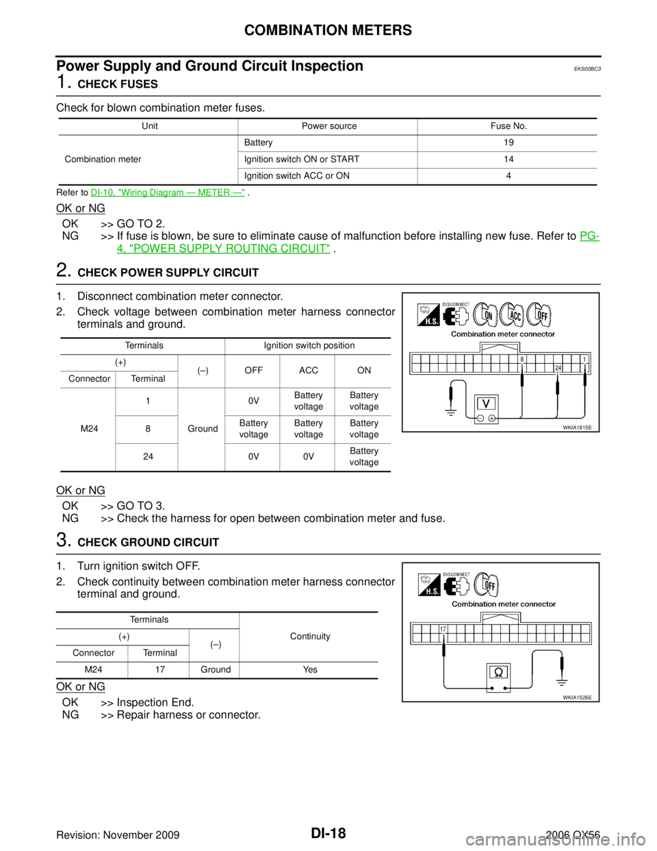
Power Supply and Ground Circuit InspectionEKS00BC3
1. CHECK FUSES
Check for blown combination meter fuses.
Refer to DI-10, "Wiring Diagram — METER —" .
OK or NG
OK >> GO TO 2.
NG >> If fuse is blown, be sure to eliminate cause of malfunction before installing new fuse. Refer to PG-
4, "POWER SUPPLY ROUTING CIRCUIT" .
2. CHECK POWER SUPPLY CIRCUIT
1. Disconnect combination meter connector.
2. Check voltage between combination meter harness connector terminals and ground.
OK or NG
OK >> GO TO 3.
NG >> Check the harness for open between combination meter and fuse.
3. CHECK GROUND CIRCUIT
1. Turn ignition switch OFF.
2. Check continuity between combination meter harness connector terminal and ground.
OK or NG
OK >> Inspection End.
NG >> Repair harness or connector.
Unit Power source Fuse No.
Combination meter Battery
19
Ignition switch ON or START 14
Ignition switch ACC or ON 4
TerminalsIgnition switch position
(+) (– )OFFACC ON
Connector Terminal
M24 1
Ground 0V
Battery
voltage Battery
voltage
8 Battery
voltage Battery
voltage Battery
voltage
24 0V 0VBattery
voltage
WKIA1815E
Terminals
Continuity
(+)
(– )
Connector Terminal
M24 17 Ground Yes
WKIA1526E
Page 1205 of 3383

DI-84
REAR VIEW MONITOR
Revision: November 20092006 QX56
Power Supply and Ground Circuit InspectionEKS00BDM
1. CHECK FUSES
Check for blown rear view camera system fuses.
OK or NG
OK >> GO TO 2.
NG >> If fuse is blown, be sure to eliminate cause of problem before installing new fuse. Refer to PG-4,
"POWER SUPPLY ROUTING CIRCUIT" .
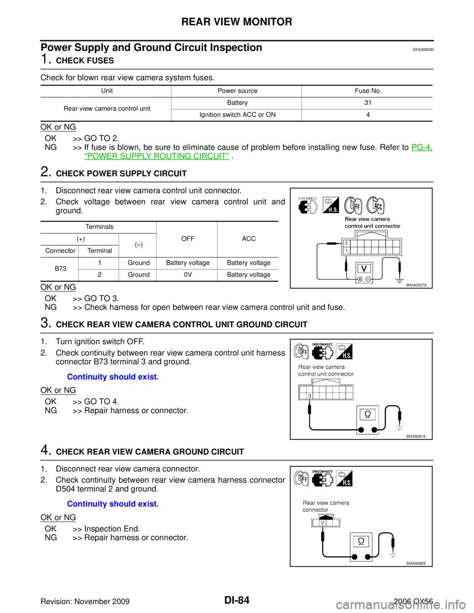
2. CHECK POWER SUPPLY CIRCUIT
1. Disconnect rear view camera control unit connector.
2. Check voltage between rear view camera control unit and ground.
OK or NG
OK >> GO TO 3.
NG >> Check harness for open between rear view camera control unit and fuse.
3. CHECK REAR VIEW CAMERA CONTROL UNIT GROUND CIRCUIT
1. Turn ignition switch OFF.
2. Check continuity between rear view camera control unit harness connector B73 terminal 3 and ground.
OK or NG
OK >> GO TO 4.
NG >> Repair harness or connector.
4. CHECK REAR VIEW CAMERA GROUND CIRCUIT
1. Disconnect rear view camera connector.
2. Check continuity between rear view camera harness connector D504 terminal 2 and ground.
OK or NG
OK >> Inspection End.
NG >> Repair harness or connector.
Unit Power source Fuse No.
Rear view camera control unit Battery
31
Ignition switch ACC or ON 4
Te r m i n a l s
OFFACC
(+)
(– )
Connector Terminal
B73 1 Ground Battery voltage Battery voltage
2 Ground
0VBattery voltage
WKIA2027E
Continuity should exist.
SKIA5081E
Continuity should exist.
SKIA5082E