Page 1962 of 3383

CYLINDER HEADEM-71
C
DE
F
G H
I
J
K L
M A
EM
Revision: November 2009 2006 QX56
5. Press the valve guide from the camshaft side to the dimensions
as shown.
CAUTION:
Cylinder head contains heat. When working, wear protec-
tive equipment to avoid getting burned.
6. Ream the cylinder head valve guide using suitable tool.
VALVE SEAT CONTACT
�After confirming that the dimensions of the valve guides and
valves are within specifications, perform this procedure.
�Apply prussian blue (or white lead) onto the contacting surface
of the valve seat to check the condition of the valve contact on
the surface.
�Check if the contact area band is continuous all around the cir-
cumference.
�If not, grind to adjust the valve fit and check again. If the contact-
ing surface still has NG conditions even after the re-check,
replace the valve seat.
VALVE SEAT REPLACEMENT
When the valve seat is removed, replace it with oversized (0.5 mm, 0.020 in) valve seat.
1. Bore out the old seat until it collapses. Boring should not continue beyond the bottom face of the seat recess in the cylinder head. Set the machine depth stop to ensure this.
2. Ream the cylinder head recess diameter for service valve seat.
�Be sure to ream in circles concentric to the valve guide center.
�This will enable valve seat to fit correctly.
KBIA2530E
Valve guide hole diameter:
Intake and exhaust : 6.000 - 6.018 mm (0.2362 - 0.2369 in)
SEM932C
SBIA0322E
Oversize [0.5 mm (0.020 in)] (Service):
Intake : 38.500 - 38.516 mm (1.5157 - 1.5164 in)
Exhaust : 32.700 - 32.716 mm (1.2874 - 1.2880 in)
SEM795A
Page 1963 of 3383
EM-72Revision: November 2009
CYLINDER HEAD
2006 QX56
3. Heat the cylinder head to 110° to 130 °C (230 ° to 266 °F) by
soaking it in heated oil.
4. Cool the valve seats well with dry ice. Force fit the valve seat into the cylinder head. CAUTION:
�Avoid directly touching cold valve seats.
�Cylinder head contains heat. When working, wear protective equipment to avoid getting burned.
5. Finish the seat to the specified dimensions using suitable tool. Refer to EM-108, "
Va l v e S e a t" .
CAUTION:
When using valve seat cutter, firmly grip the cutter handle
with both hands. Then, press on the contacting surface all
around the circumference to cut in a single drive. Improper
pressure on the cutter or cutting many different times may
result in stage valve seat.
6. Grind to obtain the dimensions indicated as shown.
�Using compound, grind to adjust valve fitting.
7. Check again for normal contact. Refer to EM-71, "
VALVE SEAT CONTACT" .
SEM008A
SEM934C
KBIA2531E
KBIA2544E
Page 1964 of 3383
CYLINDER HEADEM-73
C
DE
F
G H
I
J
K L
M A
EM
Revision: November 2009 2006 QX56
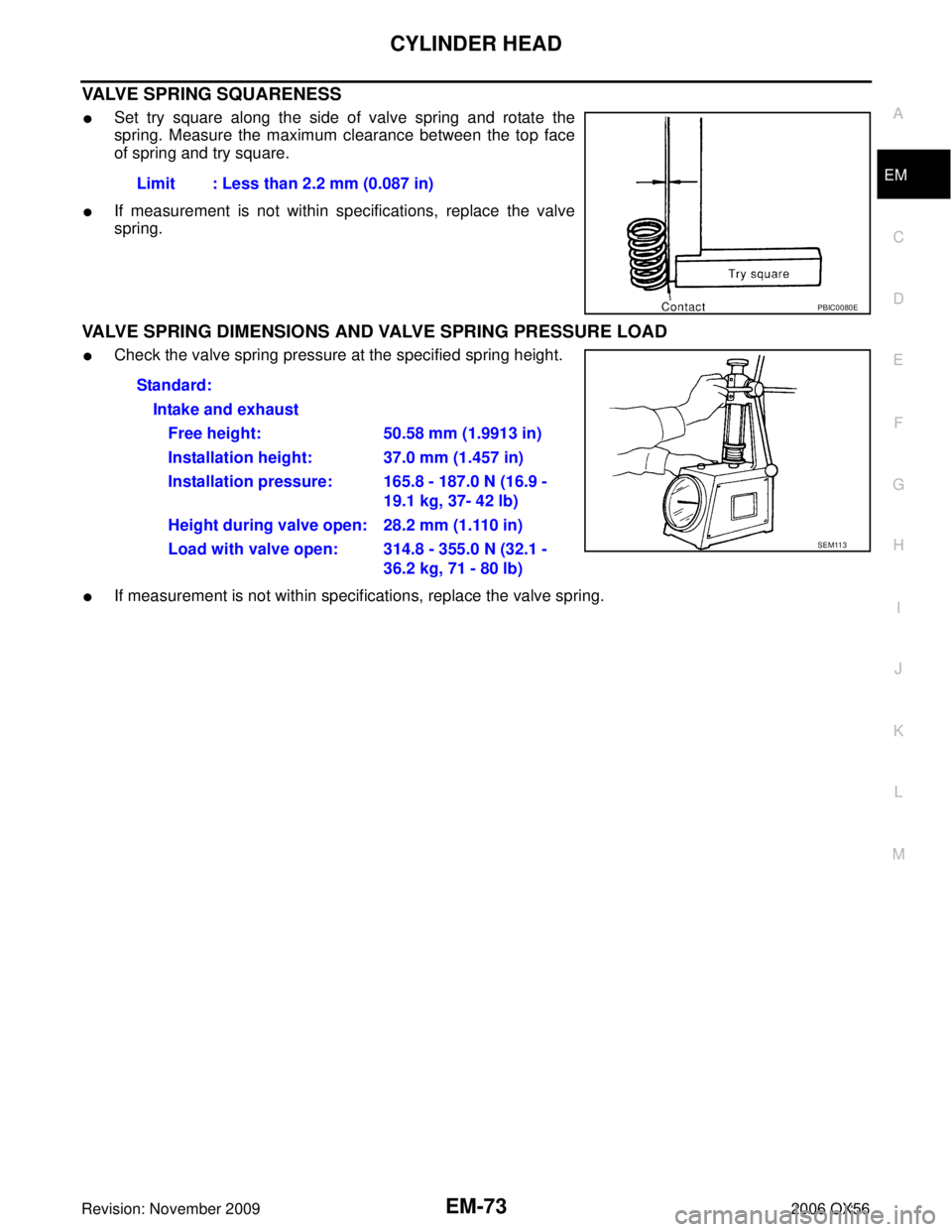
VALVE SPRING SQUARENESS
�Set try square along the side of valve spring and rotate the
spring. Measure the maximum clearance between the top face
of spring and try square.
�If measurement is not within specifications, replace the valve
spring.
VALVE SPRING DIMENSIONS AND VALVE SPRING PRESSURE LOAD
�Check the valve spring pressure at the specified spring height.
�If measurement is not within specifications, replace the valve spring.Limit : Less than 2.2 mm (0.087 in)
PBIC0080E
Standard:
Intake and exhaustFree height: 50.58 mm (1.9913 in)
Installation height: 37.0 mm (1.457 in)
Installation pressure: 165.8 - 187.0 N (16.9 - 19.1 kg, 37- 42 lb)
Height during valve open: 28.2 mm (1.110 in)
Load with valve open: 314.8 - 355.0 N (32.1 - 36.2 kg, 71 - 80 lb)
SEM113
Page 1980 of 3383

CYLINDER BLOCKEM-89
C
DE
F
G H
I
J
K L
M A
EM
Revision: November 2009 2006 QX56
2. Apply the pin diameter grade stamped on the crankshaft front
side to the column in the “Connecting Rod Bearing Selection
Ta b l e ”.
3. Read the symbol at the cross point of the selected row and col- umn in the “Connecting Rod Bearing Selection Table ”.
4. Apply the symbol obtained to the "Connecting Rod Bearing Grade Table" to select.
When Crankshaft and Connecting Rod are Reused
1. Measure dimensions of the big end inside diameter of the connecting rod and diameter of the crankshaftpin individually.
2. Apply the measured dimension to the "Connecting Rod Bearing Selection Table".
3. The following steps are the same as in “When New Connecting Rod and Crankshaft are Used ”. Refer to
EM-88, "
HOW TO SELECT CONNECTING ROD BEARING" .
Connecting Rod Bearing Selection Table
Connecting Rod Bearing Grade Table.
Undersize Bearings Usage Guide
�When the specified oil clearance is not obtained with standard size connecting rod bearings, use under-
size (US) bearings.
�When using undersize bearing, measure the bearing inside diameter with the bearing installed, and grind
the crankshaft pin so that the oil clearance satisfies the standard.
PBIC0110E
KBIA2538E
Grade number Thickness “T ” mm (in) Identification color (mark)
0 1.500 - 1.503 (0.0591 - 0.0592) Black
1 1.503 - 1.506 (0.0592 - 0.0593) Brown
2 1.506 - 1.509 (0.0593 - 0.0594) Green
3 1.509 - 1.512 (0.0594 - 0.0595) Yellow
Page 1991 of 3383

EM-100Revision: November 2009
CYLINDER BLOCK
2006 QX56
CRANKSHAFT PIN DIAMETER
�Measure diameter of crankshaft pin using suitable tool.
�If measurement is out of standard, measure connecting rod
bearing oil clearance. Then use undersize bearing. Refer to EM-
100, "CONNECTING ROD BEARING OIL CLEARANCE" .
OUT-OF-ROUND AND TAPER OF CRANKSHAFT
�Measure dimensions at four different points as shown on each
journal and pin.
�Out-of-roundness is indicated by the difference in dimension
between ″X″ and ″Y″ at ″A″ and ″B″ .
�Taper is indicated by the difference in dimension between ″A″
and ″B″ at ″X″ and ″Y″ .
�If measured value exceeds the standard, correct or replace crankshaft.
�If corrected, measure the bearing oil clearance of the corrected journal or pin. Then select the main bear-
ing or connecting rod bearing. Refer to EM-101, "
MAIN BEARING OIL CLEARANCE" or EM-100, "CON-
NECTING ROD BEARING OIL CLEARANCE" .
CRANKSHAFT RUNOUT
�Place a V-block on a precise flat table to support the journals on
both ends of the crankshaft.
�Measure at No. 3 journal using suitable tool.
�While rotating crankshaft, read the movement of the pointer.
�Half of the movement shows the runout.
�If measurement exceeds the limit, replace crankshaft.
CONNECTING ROD BEARING OIL CLEARANCE
Method of Measurement
�Install connecting rod bearings to the connecting rod and cap. Tighten connecting rod bolts to the speci-
fied torque. Refer to EM-82, "
ASSEMBLY" .
Standard : 53.956 - 53.974 mm (2.1243 - 2.1250 in)
PBIC0127E
Limit
Out-of-round (Difference between ″X″ and ″Y″ )
: 0.002 mm (0.0001 in)
Taper (Difference between ″A ″ and ″B ″)
: 0.002 mm (0.0001 in)
PBIC1685E
Limit : Less than 0.05 mm (0.002 in)
PBIC0129E
Page 1998 of 3383
SERVICE DATA AND SPECIFICATIONS (SDS)EM-107
C
DE
F
G H
I
J
K L
M A
EM
Revision: November 2009 2006 QX56
CYLINDER HEAD
Unit: mm (in)
Valve Dimensions
Unit: mm (in)
Items
StandardLimit
Head surface distortion 0.03 (0.0012)0.1 (0.004)
Nominal cylinder head height “H ” 126.3 (4.97)
KBIA2554E
Valve head diameter “D” Intake
37.0 - 37.3 (1.457 - 1.469)
Exhaust 31.2 - 31.5 (1.228 - 1.240)
Valve length “ L” Intake
96.21- 96.71 (3.7878 - 3.8075)
Exhaust 93.74 - 94.24 (3.6905 - 3.7102)
Valve stem diameter “ d” Intake
5.965 - 5.980 (0.2348 - 0.2354)
Exhaust 5.955 - 5.970 (0.2344 - 0.2350)
Valve seat angle “α ” Intake
45°15 ′ - 45 °45 ′
Exhaust
Valve margin “T ” Intake
1.1 (0.043)
Exhaust 1.3 (0.051)
SEM188
Page 2093 of 3383
GI-2Revision: November 20092006 QX56
VEHICLE IDENTIFICATION NUMBER
ARRANGEMENT ..............................................
... 48
ENGINE SERIAL NUMBER ............................. ... 49
TRANSFER SERIAL NUMBER ........................ ... 49
AUTOMATIC TRANSMISSION NUMBER ........ ... 49Dimensions ..........................................................
... 50
Wheels & Tires ..................................................... ... 50
TERMINOLOGY ..................................................... ... 51
SAE J1930 Terminology List ................................ ... 51
Page 2141 of 3383
GI-50
IDENTIFICATION INFORMATION
Revision: November 20092006 QX56
DimensionsEAS001G4
Unit: mm (in)
Wheels & TiresEAS001G5
Drive type2WD 4WD
Overall length 5255 (206.9) 5255 (206.9)
Overall width 2001 (78.8) 2001 (78.8)
Overall height (with roof rack) 1976.8 (77.8) 1997.7 (78.7)
Front tread width 1725 (67.9) 1725 (67.9)
Rear tread width 1725 (67.9) 1725 (67.9)
Wheelbase 3130 (123.2) 3130 (123.2)
Minimum Running Ground Clearance (at front sus-
pension) With standard
undercover
254.8 (10.03) 273.7 (10.77)
With oil pan skid
plate 250.5 (9.86) 269.5 (10.61)
Drive Type Grade
Road wheelTireSpare tire size
All LE7-Spoke 18x8J Chromium Aluminum
Alloy P265/70R18
P265/70R18
 by
soaking it in heated oil.
4. Cool the valve seats well with dry ice. Force fit")
EM-107
C
DE
F
G H
I
J
K L
M A
EM
Revision: November 2009 2006 QX56
CYLINDER HEAD
Unit: mm (in)
Valve Dimensions
Unit: mm (in)
Items
StandardLimit
Head surface dist")


Wheels & TiresEAS001G5
Drive type2WD 4WD
Overall length 5255 (206.9) 5255 (206.9)
Overall width 2001")