Page 3317 of 3383
WT-28
TROUBLE DIAGNOSIS FOR SELF-DIAGNOSTIC ITEMS
Revision: November 20092006 QX56
Inspection 4: Vehicle Speed SignalEES001Q3
MALFUNCTION CODE NO. 52 (DTC C1729)
1. SELF-DIAGNOSTIC RESULT CHECK
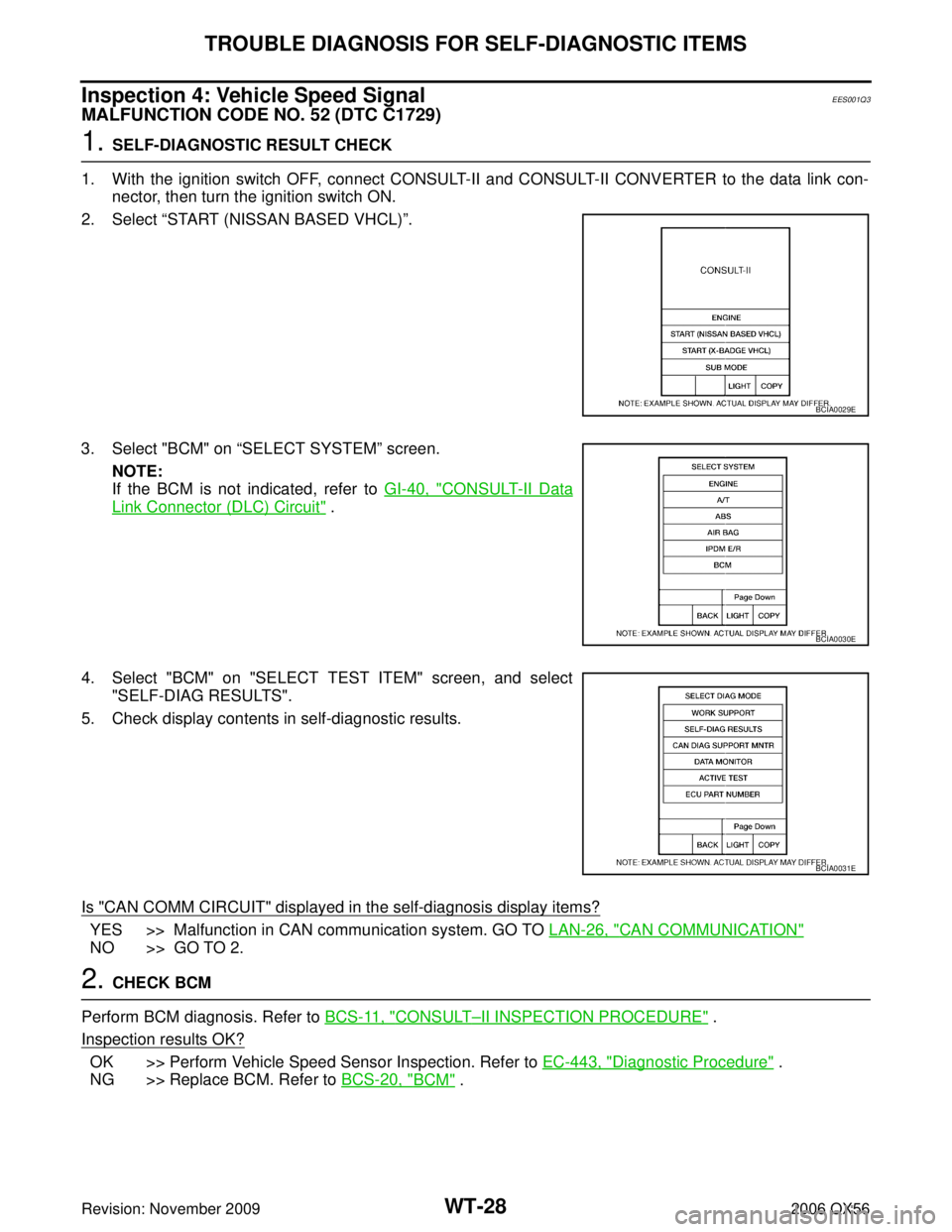
1. With the ignition switch OFF, connect CONSULT-II and CONSULT-II CONVERTER to the data link con- nector, then turn the ignition switch ON.
2. Select “START (NISSAN BASED VHCL) ”.
3. Select "BCM" on “SELECT SYSTEM” screen.
NOTE:
If the BCM is not indicated, refer to GI-40, "
CONSULT-II Data
Link Connector (DLC) Circuit" .
4. Select "BCM" on "SELECT TEST ITEM" screen, and select "SELF-DIAG RESULTS".
5. Check display contents in self-diagnostic results.
Is "CAN COMM CIRCUIT" displayed in the self-diagnosis display items?
YES >> Malfunction in CAN communication system. GO TO LAN-26, "CAN COMMUNICATION"
NO >> GO TO 2.
2. CHECK BCM
Perform BCM diagnosis. Refer to BCS-11, "
CONSULT–II INSPECTION PROCEDURE" .
Inspection results OK?
OK >> Perform Vehicle Speed Sensor Inspection. Refer to EC-443, "Diagnostic Procedure" .
NG >> Replace BCM. Refer to BCS-20, "
BCM" .
BCIA0029E
BCIA0030E
BCIA0031E
Page 3318 of 3383
TROUBLE DIAGNOSIS FOR SYMPTOMSWT-29
C
DF
G H
I
J
K L
M A
B
WT
Revision: November 2009 2006 QX56
TROUBLE DIAGNOSIS FOR SYMPTOMSPFP:00007
Inspection 1: Warning Lamp Does Not Come On When Ignition Switch Is Turned
On
EES001Q4
DIAGNOSTIC PROCEDURE
1. SELF-DIAGNOSTIC RESULT CHECK
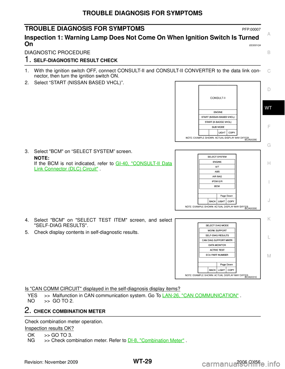
1. With the ignition switch OFF, connect CONSULT-II and CONSULT-II CONVERTER to the data link con- nector, then turn the ignition switch ON.
2. Select “START (NISSAN BASED VHCL) ”.
3. Select "BCM" on “SELECT SYSTEM” screen.
NOTE:
If the BCM is not indicated, refer to GI-40, "
CONSULT-II Data
Link Connector (DLC) Circuit" .
4. Select "BCM" on "SELECT TEST ITEM" screen, and select "SELF-DIAG RESULTS".
5. Check display contents in self-diagnostic results.
Is "CAN COMM CIRCUIT" displayed in the self-diagnosis display items?
YES >> Malfunction in CAN communication system. Go To LAN-26, "CAN COMMUNICATION" .
NO >> GO TO 2.
2. CHECK COMBINATION METER
Check combination meter operation.
Inspection results OK?
OK >> GO TO 3.
NG >> Check combination meter. Refer to DI-8, "
Combination Meter" .
BCIA0029E
BCIA0030E
BCIA0031E
Page 3319 of 3383
WT-30
TROUBLE DIAGNOSIS FOR SYMPTOMS
Revision: November 20092006 QX56
3. CHECK LOW TIRE PRESSURE WARNING LAMP
Disconnect BCM harness connector.
Does the low tire pressure warning lamp activate?
YES >> Replace BCM. Refer to BCS-20, "BCM" .
NO >> Check combination meter and repair or replace.
Inspection 2: Low Tire Pressure Warning Lamp Stays On When Ignition Switch
Is Turned On
EES001II
DIAGNOSTIC PROCEDURE
1. CHECK CONNECTOR
1. Turn ignition switch OFF.
2. Disconnect BCM harness connectors M18 and M20.
3. Check terminals for damage or loose connections.
Inspection results OK?
OK >> GO TO 2.
NG >> Repair or replace damaged parts.
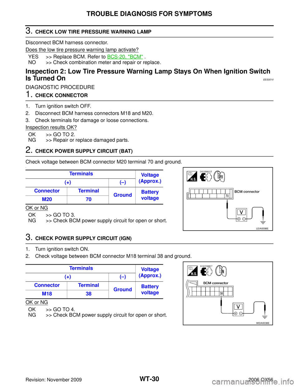
2. CHECK POWER SUPPLY CIRCUIT (BAT)
Check voltage between BCM connector M20 terminal 70 and ground.
1.
OK or NG
OK >> GO TO 3.
NG >> Check BCM power supply circuit for open or short.
3. CHECK POWER SUPPLY CIRCUIT (IGN)
1. Turn ignition switch ON.
2. Check voltage between BCM connector M18 terminal 38 and ground.
OK or NG
OK >> GO TO 4.
NG >> Check BCM power supply circuit for open or short. Te r m i n a l s
Vo l ta g e
(Approx.)
(+) (–)
Connector Terminal GroundBattery
voltage
M20 70
LEIA0098E
Te r m i n a l s
Vo l ta g e
(Approx.)
(+) (–)
Connector Terminal GroundBattery
voltage
M18 38
WEIA0038E
Page 3320 of 3383
TROUBLE DIAGNOSIS FOR SYMPTOMSWT-31
C
DF
G H
I
J
K L
M A
B
WT
Revision: November 2009 2006 QX56
4. CHECK GROUND CIRCUIT
1. Turn ignition switch OFF.
2. Check continuity between BCM connector M20 terminal 67 and ground.
OK or NG
OK >> Replace BCM. Refer to BCS-20, "BCM" .
NG >> Repair BCM ground circuit. Terminals
Continuity
(+) (–)
Connector Terminal Ground Yes
M20 67LIIA1040E
Page 3321 of 3383
WT-32
TROUBLE DIAGNOSIS FOR SYMPTOMS
Revision: November 20092006 QX56
Inspection 3: Warning Lamp Flashes When Ignition Switch Is Turned OnEES001IJ
NOTE:
If warning lamp flashes as shown, the system is normal.
Flash Mode A
�This mode shows transmitter status is OFF-mode.
Carry out transmitter wake up operation. Refer to WT-18,
"Transmitter Wake Up Operation" .
DIAGNOSTIC PROCEDURE
1. CHECK CONNECTOR
1. Turn ignition switch OFF.
2. Disconnect BCM harness connectors M18 and M20.
3. Check terminals for damage or loose connections.
Inspection results OK?
OK >> GO TO 2.
NG >> Repair or replace damaged parts.
2. CHECK TIRE PRESSURE WARNING CHECK CONNECTOR CIRCUIT
Check continuity between BCM connector M18 terminal 15 and tire pressure warning check connector M123
terminal 1.
OK or NG
OK >> Replace BCM. Refer to BCS-20, "BCM" .
NG >> Repair or replace harness connector.
SEIA0347E
1 - 15 Continuity should exist
WEIA0097E
Page 3322 of 3383
TROUBLE DIAGNOSIS FOR SYMPTOMSWT-33
C
DF
G H
I
J
K L
M A
B
WT
Revision: November 2009 2006 QX56
Inspection 4: Hazard Warning Lamp Flashes When Ignition Switch Is Turned OnEES001IK
DIAGNOSTIC PROCEDURE
1. CHECK GROUND CIRCUIT
1. Turn ignition switch OFF.
2. Disconnect BCM harness connector M20.
3. Check continuity between BCM connector M20 terminal 67 and ground.
OK or NG
OK >> Replace BCM. Refer to BCS-20, "BCM" .
NG >> Repair BCM ground circuit. Te r m i n a l s
Continuity
(+) (–)
Connector Terminal Ground Yes
M20 67
LIIA1040E
Page 3323 of 3383
WT-34
TROUBLE DIAGNOSIS FOR SYMPTOMS
Revision: November 20092006 QX56
Inspection 5: “TIRE PRESSURE” Information In Display Unit Does Not ExistEES001Q5
DIAGNOSTIC PROCEDURE
1. SELF-DIAGNOSTIC RESULT CHECK
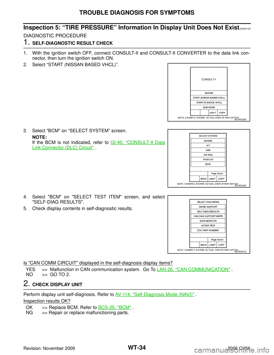
1. With the ignition switch OFF, connect CONSULT-II and CONSULT-II CONVERTER to the data link con- nector, then turn the ignition switch ON.
2. Select “START (NISSAN BASED VHCL) ”.
3. Select "BCM" on “SELECT SYSTEM” screen.
NOTE:
If the BCM is not indicated, refer to GI-40, "
CONSULT-II Data
Link Connector (DLC) Circuit" .
4. Select "BCM" on "SELECT TEST ITEM" screen, and select "SELF-DIAG RESULTS".
5. Check display contents in self-diagnostic results.
Is "CAN COMM CIRCUIT" displayed in the self-diagnosis display items?
YES >> Malfunction in CAN communication system. Go To LAN-26, "CAN COMMUNICATION" .
NO >> GO TO 2.
2. CHECK DISPLAY UNIT
Perform display unit self-diagnosis. Refer to AV- 11 4 , "
Self-Diagnosis Mode (NAVI)" .
Inspection results OK?
OK >> Replace BCM. Refer to BCS-20, "BCM" .
NG >> Repair or replace malfunctioning parts.
BCIA0029E
BCIA0030E
BCIA0031E
Page 3331 of 3383
WW-4
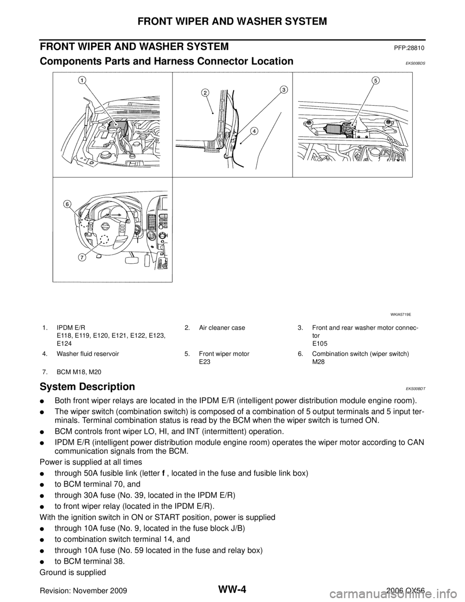
FRONT WIPER AND WASHER SYSTEM
Revision: November 20092006 QX56
FRONT WIPER AND WASHER SYSTEMPFP:28810
Components Parts and Harness Connector LocationEKS00BDS
System DescriptionEKS00BDT
�Both front wiper relays are located in the IPDM E/R (intelligent power distribution module engine room).
�The wiper switch (combination switch) is composed of a combination of 5 output terminals and 5 input ter-
minals. Terminal combination status is read by the BCM when the wiper switch is turned ON.
�BCM controls front wiper LO, HI, and INT (intermittent) operation.
�IPDM E/R (intelligent power distribution module engine room) operates the wiper motor according to CAN
communication signals from the BCM.
Power is supplied at all times
�through 50A fusible link (letter f , located in the fuse and fusible link box)
�to BCM terminal 70, and
�through 30A fuse (No. 39, located in the IPDM E/R)
�to front wiper relay (located in the IPDM E/R).
With the ignition switch in ON or START position, power is supplied
�through 10A fuse (No. 9, located in the fuse block J/B)
�to combination switch terminal 14, and
�through 10A fuse (No. 59 located in the fuse and relay box)
�to BCM terminal 38.
Ground is supplied
WKIA5719E
1. IPDM E/R E118, E119, E120, E121, E122, E123,
E124 2. Air cleaner case 3. Front and rear washer motor connec-
tor
E105
4. Washer fluid reservoir 5. Front wiper motor E236. Combination switch (wiper switch)
M28
7. BCM M18, M20