Page 1250 of 5621
BODY REPAIR
BL-311
C
D
E
F
G
H
J
K
L
MA
B
BL
Revision: 2006 January2006 M35/M45
The spot weld on HSS panels is harder than that of an ordi-
nary steel panel.
Therefore, when cutting spot welds on a HSS panel, use a
low speed high torque drill (1,000 to 1,200 rpm) to increase
drill bit durability and facilitate the operation.
2. Precautions in spot welding HSS
This work should be performed under standard working condi-
tions. Always note the following when spot welding HSS:
The electrode tip diameter must be sized properly according
to the metal thickness.
The panel surfaces must fit flush to each other, leaving no
gaps.
Follow the specifications for the proper welding pitch.
Unit: mm
PIIA0145E
PIIA0146E
PIIA0147E
Thickness (t) Minimum pitch (l)
0.6 (0.024)
0.8 (0.031)
1.0 (0.039)
1.2 (0.047)
1.6 (0.063)
1.8 (0.071)10 (0.39) or over
12 (0.47) or over
18 (0.71) or over
20 (0.79) or over
27 (1.06) or over
31 (1.22) or over
PIIA0148E
Page 1251 of 5621

BL-312
BODY REPAIR
Revision: 2006 January2006 M35/M45
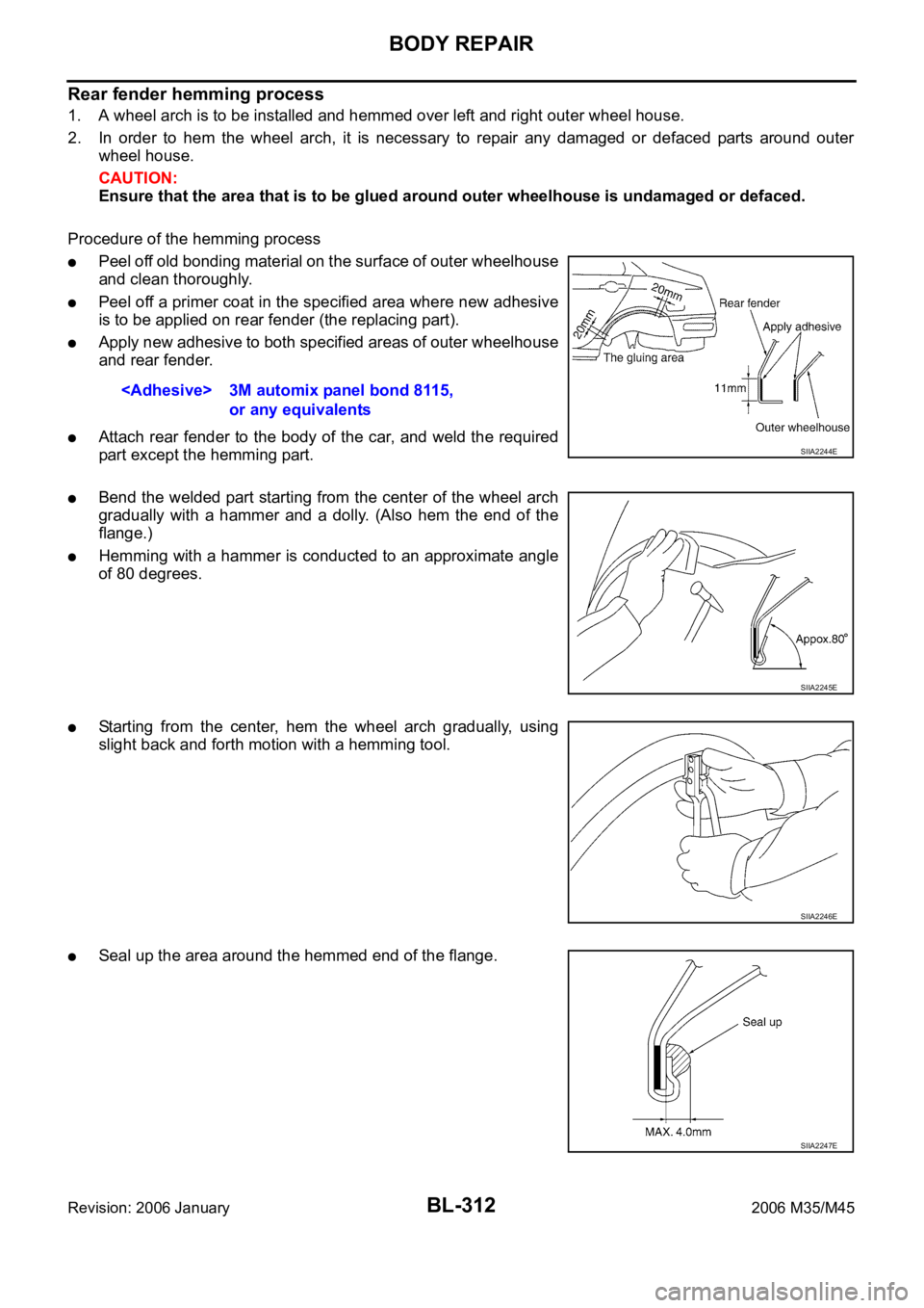
Rear fender hemming process
1. A wheel arch is to be installed and hemmed over left and right outer wheel house.
2. In order to hem the wheel arch, it is necessary to repair any damaged or defaced parts around outer
wheel house.
CAUTION:
Ensure that the area that is to be glued around outer wheelhouse is undamaged or defaced.
Procedure of the hemming process
Peel off old bonding material on the surface of outer wheelhouse
and clean thoroughly.
Peel off a primer coat in the specified area where new adhesive
is to be applied on rear fender (the replacing part).
Apply new adhesive to both specified areas of outer wheelhouse
and rear fender.
Attach rear fender to the body of the car, and weld the required
part except the hemming part.
Bend the welded part starting from the center of the wheel arch
gradually with a hammer and a dolly. (Also hem the end of the
flange.)
Hemming with a hammer is conducted to an approximate angle
of 80 degrees.
Starting from the center, hem the wheel arch gradually, using
slight back and forth motion with a hemming tool.
Seal up the area around the hemmed end of the flange. 3M automix panel bond 8115,
or any equivalents
SIIA2244E
SIIA2245E
SIIA2246E
SIIA2247E
Page 1271 of 5621
BL-332
BODY REPAIR
Revision: 2006 January2006 M35/M45
REAR PANEL
Change parts
Rear panel assembly
SIIA2493E
Page 1272 of 5621
BODY REPAIR
BL-333
C
D
E
F
G
H
J
K
L
MA
B
BL
Revision: 2006 January2006 M35/M45
REAR FLOOR REAR
Work after rear panel has been removed.
SIIA2494E
Page 1274 of 5621
BODY REPAIR
BL-335
C
D
E
F
G
H
J
K
L
MA
B
BL
Revision: 2006 January2006 M35/M45
REAR SIDE MEMBER EXTENSION
Work after rear panel has been removed.
SIIA2495E
Page 1281 of 5621
BR-6
BRAKE PEDAL
Revision: 2006 January2006 M35/M45
BRAKE PEDALPFP:46501
Inspection and AdjustmentNFS000OS
Play and clearance inspection between brake pedal and floor panel with pedal depressed.
Check brake pedal play.
Check brake pedal height from dash lower panel (1).
Adjust height referring to the following specifications.
SFIA2743J
H1Brake pedal height (from dash lower panel top surface) 157 167 mm (6.18 6.57 in)
H
2Depressed brake pedal height
[under a force of 490 N (50 kg, 110 lb) with engine running]90 mm (3.54 in) or more
CClearance between threaded end of the stop lamp switch/brake switch
(2) and bracket (3)0.74
1.96 mm (0.0291 0.0772 in)
A Pedal play 3
11 mm (0.12 0.43 in)
Page 1283 of 5621

BR-8
BRAKE PEDAL
Revision: 2006 January2006 M35/M45
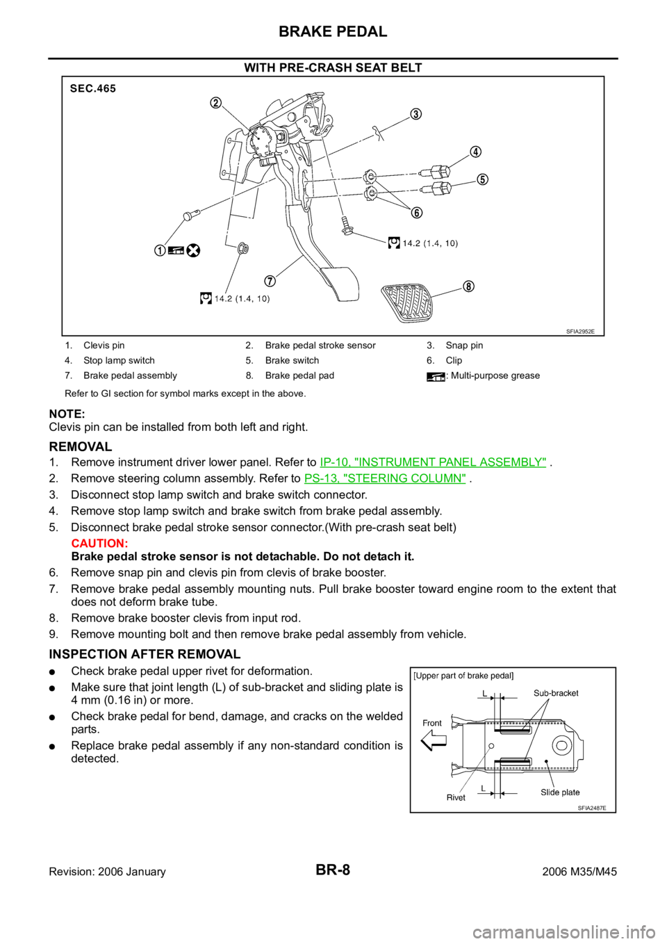
WITH PRE-CRASH SEAT BELT
NOTE:
Clevis pin can be installed from both left and right.
REMOVAL
1. Remove instrument driver lower panel. Refer to IP-10, "INSTRUMENT PANEL ASSEMBLY" .
2. Remove steering column assembly. Refer to PS-13, "
STEERING COLUMN" .
3. Disconnect stop lamp switch and brake switch connector.
4. Remove stop lamp switch and brake switch from brake pedal assembly.
5. Disconnect brake pedal stroke sensor connector.(With pre-crash seat belt)
CAUTION:
Brake pedal stroke sensor is not detachable. Do not detach it.
6. Remove snap pin and clevis pin from clevis of brake booster.
7. Remove brake pedal assembly mounting nuts. Pull brake booster toward engine room to the extent that
does not deform brake tube.
8. Remove brake booster clevis from input rod.
9. Remove mounting bolt and then remove brake pedal assembly from vehicle.
INSPECTION AFTER REMOVAL
Check brake pedal upper rivet for deformation.
Make sure that joint length (L) of sub-bracket and sliding plate is
4 mm (0.16 in) or more.
Check brake pedal for bend, damage, and cracks on the welded
parts.
Replace brake pedal assembly if any non-standard condition is
detected.
SFIA2952E
1. Clevis pin 2. Brake pedal stroke sensor 3. Snap pin
4. Stop lamp switch 5. Brake switch 6. Clip
7. Brake pedal assembly 8. Brake pedal pad : Multi-purpose grease
Refer to GI section for symbol marks except in the above.
SFIA2487E
Page 1293 of 5621
BR-18
BRAKE BOOSTER
Revision: 2006 January2006 M35/M45
BRAKE BOOSTERPFP:47200
On-Board Inspection and ServiceNFS000P6
OPERATION CHECK
With engine stopped, change vacuum to atmospheric pressure by
depressing brake pedal several times. Then with brake pedal fully
depressed, start engine and when vacuum pressure reaches the
standard, make sure that clearance between brake pedal and floor
panel decreases.
AIR TIGHT CHECK
Run engine at idle for approximately 1 minute, and stop it after
applying vacuum to booster. Depress brake pedal normally to
change vacuum to atmospheric pressure. Make sure that dis-
tance at intervals of 5 seconds between brake pedal and floor
panel gradually increases.
Depress brake pedal while engine is running, and stop engine
with pedal depressed. The pedal stroke should not change after
holding pedal down for 30 seconds.
BRA0037D
SBR365AA