2006 INFINITI M35 check engine
[x] Cancel search: check enginePage 4588 of 5621

ACTIVE AFS
LT-161
C
D
E
F
G
H
I
J
L
MA
B
LT
Revision: 2006 January2006 M35/M45
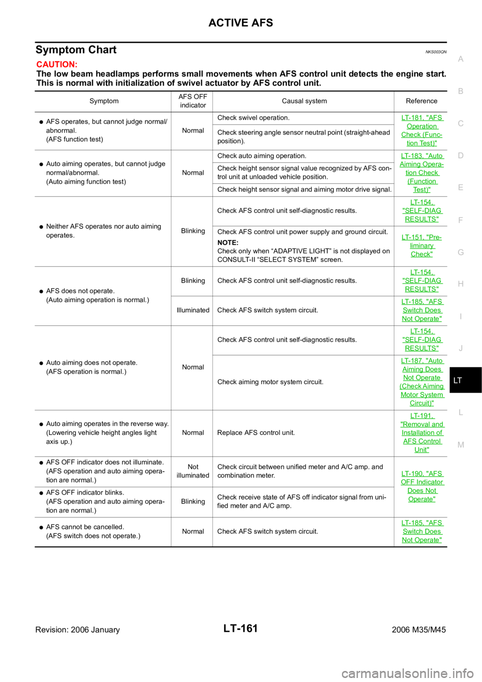
Symptom ChartNKS003QN
CAUTION:
The low beam headlamps performs small movements when AFS control unit detects the engine start.
This is normal with initialization of swivel actuator by AFS control unit.
SymptomAFS OFF
indicatorCausal system Reference
AFS operates, but cannot judge normal/
abnormal.
(AFS function test)NormalCheck swivel operation.LT-181, "AFS
Operation
Check (Func-
tion Test)"
Check steering angle sensor neutral point (straight-ahead
position).
Auto aiming operates, but cannot judge
normal/abnormal.
(Auto aiming function test)NormalCheck auto aiming operation.LT-183, "Auto
Aiming Opera-
tion Check
(Function
Te s t )"
Check height sensor signal value recognized by AFS con-
trol unit at unloaded vehicle position.
Check height sensor signal and aiming motor drive signal.
Neither AFS operates nor auto aiming
operates.BlinkingCheck AFS control unit self-diagnostic results. LT-154,
"SELF-DIAG
RESULTS"
Check AFS control unit power supply and ground circuit.
NOTE:
Check only when “ADAPTIVE LIGHT” is not displayed on
CONSULT-II “SELECT SYSTEM” screen.LT-151, "Pre-
liminary
Check"
AFS does not operate.
(Auto aiming operation is normal.)Blinking Check AFS control unit self-diagnostic results. LT-154,
"SELF-DIAG
RESULTS"
Illuminated Check AFS switch system circuit.LT-185, "
AFS
Switch Does
Not Operate"
Auto aiming does not operate.
(AFS operation is normal.)NormalCheck AFS control unit self-diagnostic results. LT-154,
"SELF-DIAG
RESULTS"
Check aiming motor system circuit.LT-187, "
Auto
Aiming Does
Not Operate
(Check Aiming
Motor System
Circuit)"
Auto aiming operates in the reverse way.
(Lowering vehicle height angles light
axis up.)Normal Replace AFS control unit.LT-191, "Removal and
Installation of
AFS Control
Unit"
AFS OFF indicator does not illuminate.
(AFS operation and auto aiming opera-
tion are normal.)Not
illuminatedCheck circuit between unified meter and A/C amp. and
combination meter.LT-190, "
AFS
OFF Indicator
Does Not
Operate"AFS OFF indicator blinks.
(AFS operation and auto aiming opera-
tion are normal.)BlinkingCheck receive state of AFS off indicator signal from uni-
fied meter and A/C amp.
AFS cannot be cancelled.
(AFS switch does not operate.)Normal Check AFS switch system circuit.LT-185, "AFS
Switch Does
Not Operate"
Page 4608 of 5621

ACTIVE AFS
LT-181
C
D
E
F
G
H
I
J
L
MA
B
LT
Revision: 2006 January2006 M35/M45
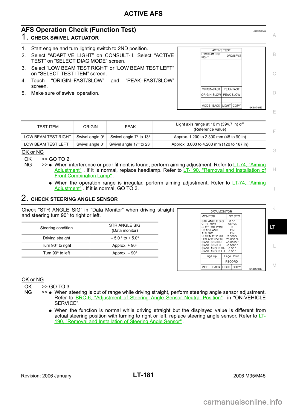
AFS Operation Check (Function Test)NKS003QS
1. CHECK SWIVEL ACTUATOR
1. Start engine and turn lighting switch to 2ND position.
2. Select “ADAPTIVE LIGHT” on CONSULT-II. Select “ACTIVE
TEST” on “SELECT DIAG MODE” screen.
3. Select “LOW BEAM TEST RIGHT” or “LOW BEAM TEST LEFT”
on “SELECT TEST ITEM” screen.
4. Touch “ORIGIN–FAST/SLOW” and “PEAK–FAST/SLOW”
screen.
5. Make sure of swivel operation.
OK or NG
OK >> GO TO 2.
NG >>
When interference or poor fitment is found, perform aiming adjustment. Refer to LT- 7 4 , "Aiming
Adjustment" . If it is normal, replace headlamp. Refer to LT- 1 9 0 , "Removal and Installation of
Front Combination Lamp" .
When the operation range is irregular, perform aiming adjustment. Refer to LT- 7 4 , "Aiming
Adjustment" . If it is normal, GO TO 3.
2. CHECK STEERING ANGLE SENSOR
Check “STR ANGLE SIG” in “Data Monitor” when driving straight
and steering turn 90
to right or left.
OK or NG
OK >> GO TO 3.
NG >>
When steering is out of range while driving straight, perform steering angle sensor adjustment.
Refer to BRC-6, "
Adjustment of Steering Angle Sensor Neutral Position" in “ON-VEHICLE
SERVICE”.
When the function is normal while driving straight but the displayed value is different from
actual steering position with turning to right or left, replace steering angle sensor. Refer to LT-
190, "Removal and Installation of Steering Angle Sensor" .
SKIB4794E
TEST ITEM ORIGIN PEAKLight axis range at 10 m (394.7 in) off
(Reference value)
LOW BEAM TEST RIGHT Swivel angle 0
Swivel angle 7 to 13Approx. 1.200 to 2.300 mm (48 to 90 in)
LOW BEAM TEST LEFT Swivel angle 0
Swivel angle 17 to 23Approx. 3.000 to 4.200 mm (120 to 167 in)
Steering conditionSTR ANGLE SIG
(Data monitor)
Driving straight
5.0 to + 5.0
Turn 90 to right Approx. + 90
Tu rn 90 to left Approx. 90
SKIB4793E
Page 4610 of 5621

ACTIVE AFS
LT-183
C
D
E
F
G
H
I
J
L
MA
B
LT
Revision: 2006 January2006 M35/M45
Auto Aiming Operation Check (Function Test)NKS003QT
1. CHECK AIMING MOTOR
1. Start engine and turn lighting switch to 2ND position.
2. Select “ADAPTIVE LIGHT” on CONSULT-II. Select “ACTIVE
TEST” on “SELECT DIAG MODE” screen.
3. Select “LEVELIZER TEST” on “SELECT TEST ITEM” screen.
4. Touch “ORIGIN” and “PEAK” screen.
5. Make sure of auto aiming operation.
OK or NG
OK >> GO TO 2.
NG >>
When interference or poor fitment is found, perform aiming adjustment. Refer to LT- 7 4 , "Aiming
Adjustment" . If it is normal, replace headlamp. Refer to LT- 1 9 0 , "Removal and Installation of
Front Combination Lamp" .
When the operation range is irregular, perform aiming adjustment. Refer to LT- 7 4 , "Aiming
Adjustment" . If it is normal, GO TO 4.
2. PERFORM STATE LEVELIZER ADJUSTMENT 1
Check “LEV ACTR VLTG” in “Data Monitor” with unloaded vehicle
position. (Remove all loads in driver, passenger and trunk rooms.)
OK or NG
OK >> GO TO 3.
NG >> Perform LEVELIZER ADJUSTMENT. Refer to LT- 1 5 3 ,
"WORK SUPPORT (LEVELIZER ADJUSTMENT)" .
3. PERFORM STATE LEVELIZER ADJUSTMENT 2
Check if “LEV ACTR VLTG” changes approx. 3 seconds after lower-
ing vehicle height as low as approx.
0.5V from the value of “HI SEN
OTP RR” in “Data Monitor” at unloaded vehicle position. (Remove all
loads in driver, passenger and trunk rooms.)
OK or NG
OK >> GO TO 4.
NG >> Perform LEVELIZER ADJUSTMENT. Refer to LT- 1 5 3 ,
"WORK SUPPORT (LEVELIZER ADJUSTMENT)" .
SKIB4796E
TEST ITEM ORIGIN PEAK (Reference value)Light axis range at 10 m (394.7 in) off
(Reference value)
LEVELIZER TEST Light axis angle 0
Light axis angle approx. 2.5Approx. 450 mm (17.7 in)
TEST ITEM Unloaded vehicle position
LEV ACTR VLTG Approx. 70%
SKIB4793E
SKIB4793E
Page 4614 of 5621

ACTIVE AFS
LT-187
C
D
E
F
G
H
I
J
L
MA
B
LT
Revision: 2006 January2006 M35/M45
Auto Aiming Does Not Operate (Check Aiming Motor System Circuit)NKS003QV
1. CHECK AIMING MOTOR
1. Start engine and turn lighting switch to 2ND position.
2. Select “ADAPTIVE LIGHT” on CONSULT-II. Select “ACTIVE
TEST” on “SELECT DIAG MODE” screen.
3. Select “LEVELIZER TEST” on “SELECT TEST ITEM” screen.
4. Touch “ORIGIN” or “PEAK” screen.
5. Make sure of aiming motor operation.
OK or NG
OK >> Replace AFS control unit. Refer to LT- 1 9 1 , "Removal
and Installation of AFS Control Unit" .
NG >> GO TO 2.
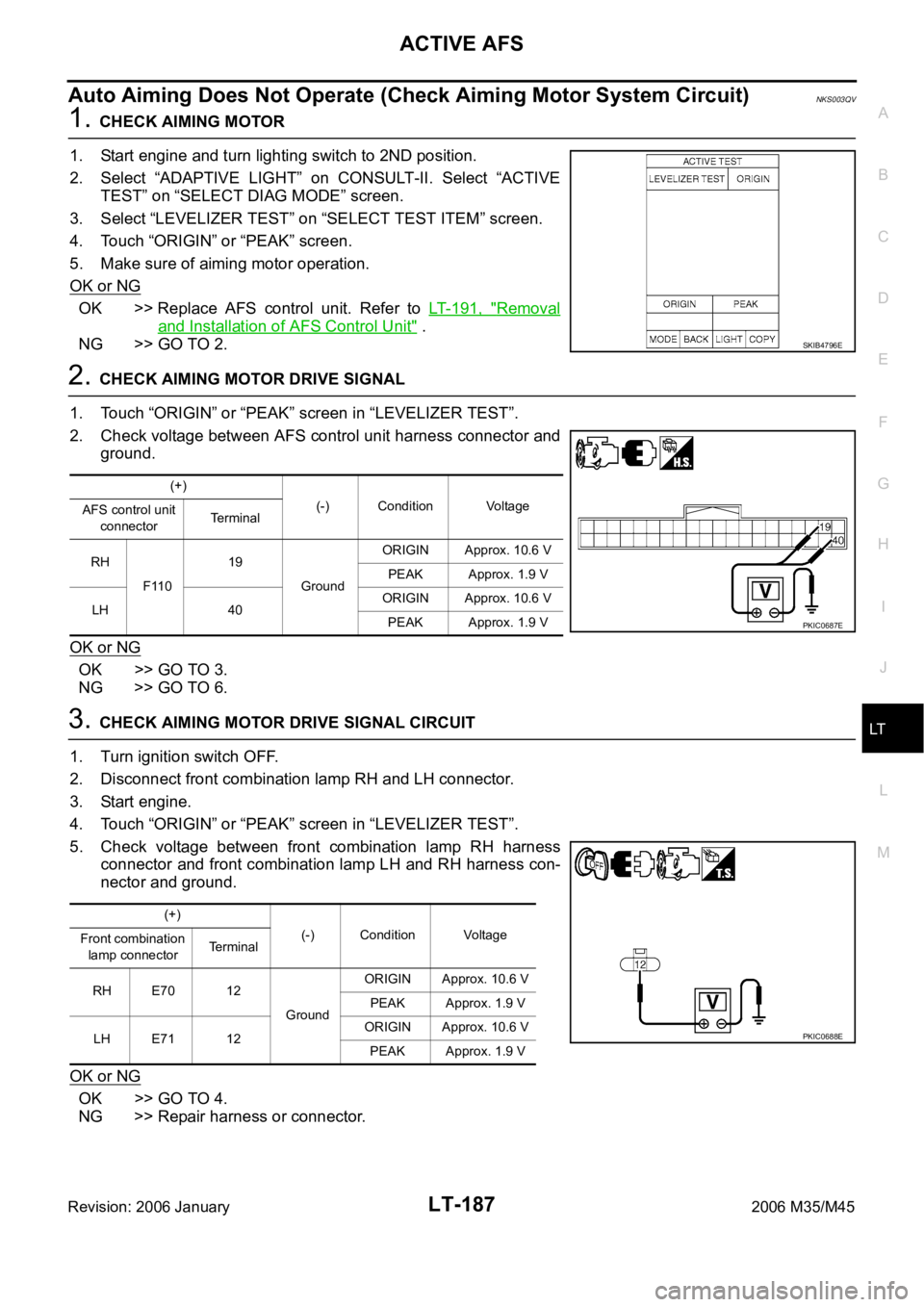
2. CHECK AIMING MOTOR DRIVE SIGNAL
1. Touch “ORIGIN” or “PEAK” screen in “LEVELIZER TEST”.
2. Check voltage between AFS control unit harness connector and
ground.
OK or NG
OK >> GO TO 3.
NG >> GO TO 6.
3. CHECK AIMING MOTOR DRIVE SIGNAL CIRCUIT
1. Turn ignition switch OFF.
2. Disconnect front combination lamp RH and LH connector.
3. Start engine.
4. Touch “ORIGIN” or “PEAK” screen in “LEVELIZER TEST”.
5. Check voltage between front combination lamp RH harness
connector and front combination lamp LH and RH harness con-
nector and ground.
OK or NG
OK >> GO TO 4.
NG >> Repair harness or connector.
SKIB4796E
(+)
(-) Condition Voltage
AFS control unit
connectorTerminal
RH
F11019
GroundORIGIN Approx. 10.6 V
PEAK Approx. 1.9 V
LH 40ORIGIN Approx. 10.6 V
PEAK Approx. 1.9 V
PKIC0687E
(+)
(-) Condition Voltage
Front combination
lamp connectorTerminal
RH E70 12
GroundORIGIN Approx. 10.6 V
PEAK Approx. 1.9 V
LH E71 12ORIGIN Approx. 10.6 V
PEAK Approx. 1.9 V
PKIC0688E
Page 4615 of 5621

LT-188
ACTIVE AFS
Revision: 2006 January2006 M35/M45
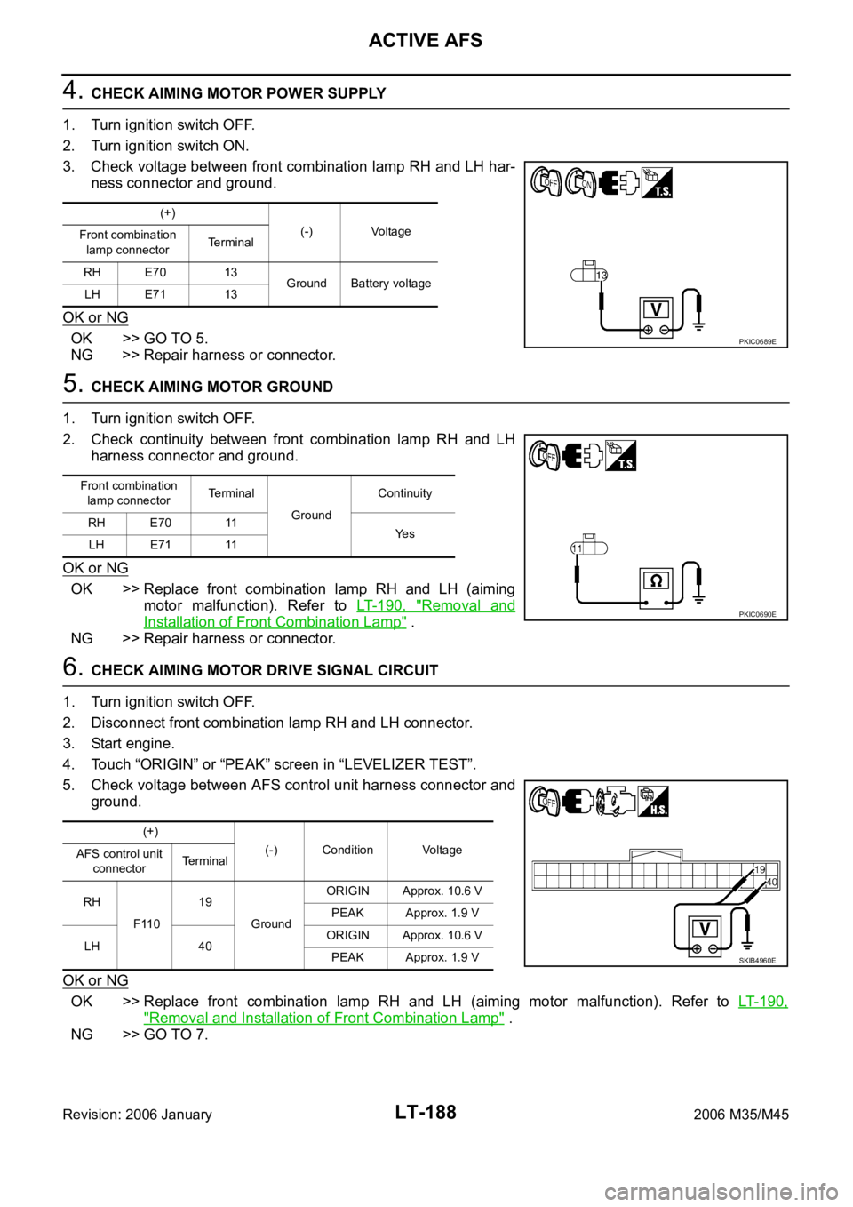
4. CHECK AIMING MOTOR POWER SUPPLY
1. Turn ignition switch OFF.
2. Turn ignition switch ON.
3. Check voltage between front combination lamp RH and LH har-
ness connector and ground.
OK or NG
OK >> GO TO 5.
NG >> Repair harness or connector.
5. CHECK AIMING MOTOR GROUND
1. Turn ignition switch OFF.
2. Check continuity between front combination lamp RH and LH
harness connector and ground.
OK or NG
OK >> Replace front combination lamp RH and LH (aiming
motor malfunction). Refer to LT- 1 9 0 , "
Removal and
Installation of Front Combination Lamp" .
NG >> Repair harness or connector.
6. CHECK AIMING MOTOR DRIVE SIGNAL CIRCUIT
1. Turn ignition switch OFF.
2. Disconnect front combination lamp RH and LH connector.
3. Start engine.
4. Touch “ORIGIN” or “PEAK” screen in “LEVELIZER TEST”.
5. Check voltage between AFS control unit harness connector and
ground.
OK or NG
OK >> Replace front combination lamp RH and LH (aiming motor malfunction). Refer to LT- 1 9 0 ,
"Removal and Installation of Front Combination Lamp" .
NG >> GO TO 7.
(+)
(-) Voltage
Front combination
lamp connectorTerminal
RH E70 13
Ground Battery voltage
LH E71 13
PKIC0689E
Front combination
lamp connectorTerminal
GroundContinuity
RH E70 11
Ye s
LH E71 11
PKIC0690E
(+)
(-) Condition Voltage
AFS control unit
connectorTerminal
RH
F11019
GroundORIGIN Approx. 10.6 V
PEAK Approx. 1.9 V
LH 40ORIGIN Approx. 10.6 V
PEAK Approx. 1.9 V
SKIB4960E
Page 4744 of 5621

LU-1
ENGINE LUBRICATION SYSTEM
B ENGINE
CONTENTS
C
D
E
F
G
H
I
J
K
L
M
SECTION LU
A
LU
Revision: 2006 January2006 M35/M45
ENGINE LUBRICATION SYSTEM
VQ35DE
PRECAUTIONS .......................................................... 3
Precautions for Liquid Gasket .................................. 3
LIQUID GASKET APPLICATION PROCEDURE ..... 3
PREPARATION ........................................................... 4
Special Service Tools ............................................... 4
Commercial Service Tools ........................................ 4
LUBRICATION SYSTEM ............................................ 5
Lubrication Circuit .................................................... 5
System Chart ........................................................... 6
ENGINE OIL ............................................................... 7
Inspection ................................................................. 7
ENGINE OIL LEVEL ............................................. 7
ENGINE OIL APPEARANCE ................................ 7
ENGINE OIL LEAKAGE ........................................ 7
OIL PRESSURE CHECK ...................................... 8
Changing Engine Oil ................................................ 9
OIL FILTER ............................................................... 10
Removal and Installation ........................................ 10
REMOVAL ........................................................
... 10
INSTALLATION ................................................... 10
INSPECTION AFTER INSTALLATION ............... 10
OIL FILTER BRACKET (AWD) ................................. 12
Components ........................................................... 12
Removal and Installation ........................................ 12
REMOVAL ........................................................
... 12
INSTALLATION ................................................... 12
INSPECTION AFTER INSTALLATION ............... 13
OIL COOLER ............................................................ 14
Components ........................................................... 14
Removal and Installation ........................................ 15
REMOVAL ........................................................
... 15
INSPECTION AFTER REMOVAL ....................... 16
INSTALLATION ................................................... 16
INSPECTION AFTER INSTALLATION ............... 16
OIL PUMP ................................................................. 18
Components ........................................................... 18
Removal and Installation ........................................ 18
REMOVAL ........................................................
... 18
INSTALLATION ................................................... 18INSPECTION AFTER INSTALLATION ................ 18
Disassembly and Assembly .................................... 18
DISASSEMBLY ................................................... 18
INSPECTION AFTER DISASSEMBLY ................ 19
ASSEMBLY ......................................................... 20
SERVICE DATA AND SPECIFICATIONS (SDS) ...... 21
Standard and Limit .................................................. 21
ENGINE OIL PRESSURE ................................... 21
ENGINE OIL CAPACITY (APPROXIMATE) ........ 21
OIL PUMP ........................................................... 21
REGULATOR VALVE .......................................... 21
VK45DE
PRECAUTIONS ........................................................ 22
Precautions for Liquid Gasket ................................ 22
LIQUID GASKET APPLICATION PROCEDURE ... 22
PREPARATION ......................................................... 23
Special Service Tools ............................................. 23
Commercial Service Tools ...................................... 23
LUBRICATION SYSTEM .......................................... 24
Lubrication Circuit ................................................... 24
System Chart .......................................................... 25
ENGINE OIL .............................................................. 26
Inspection ............................................................... 26
ENGINE OIL LEVEL ............................................ 26
ENGINE OIL APPEARANCE .............................. 26
ENGINE OIL LEAKAGE ...................................... 26
OIL PRESSURE CHECK .................................... 26
Changing Engine Oil ............................................
... 28
OIL FILTER ............................................................... 29
Removal and Installation ........................................ 29
REMOVAL ........................................................
... 29
INSTALLATION ................................................... 29
INSPECTION AFTER INSTALLATION ................ 29
OIL PUMP ................................................................. 30
Components ........................................................... 30
Removal and Installation ........................................ 30
REMOVAL ........................................................
... 30
INSTALLATION ................................................... 30
Page 4750 of 5621
![INFINITI M35 2006 Factory Service Manual ENGINE OIL
LU-7
[VQ35DE]
C
D
E
F
G
H
I
J
K
L
MA
LU
Revision: 2006 January2006 M35/M45
ENGINE OILPFP:KLA92
InspectionNBS004PW
ENGINE OIL LEVEL
NOTE:
Before starting engine, put vehicle horizontally and INFINITI M35 2006 Factory Service Manual ENGINE OIL
LU-7
[VQ35DE]
C
D
E
F
G
H
I
J
K
L
MA
LU
Revision: 2006 January2006 M35/M45
ENGINE OILPFP:KLA92
InspectionNBS004PW
ENGINE OIL LEVEL
NOTE:
Before starting engine, put vehicle horizontally and](/manual-img/42/57023/w960_57023-4749.png)
ENGINE OIL
LU-7
[VQ35DE]
C
D
E
F
G
H
I
J
K
L
MA
LU
Revision: 2006 January2006 M35/M45
ENGINE OILPFP:KLA92
InspectionNBS004PW
ENGINE OIL LEVEL
NOTE:
Before starting engine, put vehicle horizontally and check the engine oil level. If engine is already started, stop
it and allow 10 minutes before checking.
1. Pull out oil level gauge and wipe it clean.
2. Insert oil level gauge and make sure the engine oil level is within
the range shown in the figure.
3. If it is out of range, adjust it.
NOTE:
When checking the engine oil level, insert oil level gauge with its
tip aligned with oil level gauge guide on cylinder head. (In figure,
air cleaner case and air duct are removed.)
ENGINE OIL APPEARANCE
Check engine oil for white turbidity or heavy contamination.
If engine oil becomes turbid and white, it is highly probable that it is contaminated with engine coolant.
Repair or replace damaged parts.
ENGINE OIL LEAKAGE
Check for engine oil leakage around the following areas:
Oil pans (lower and upper)
Oil pan drain plug
Oil pressure switch
Oil filter
Oil filter bracket (AWD models)
Oil cooler
Water pump cover
Chain tensioner cover
Intake valve timing control cover and intake valve timing control solenoid valve
Mating surface between cylinder head and rocker cover
Mating surface between front timing chain case and rear timing chain case
Mating surface between rear timing chain case and cylinder head
Mating surface between rear timing chain case and cylinder block
Mating surface between rear timing chain case and oil pan (upper)
Mating surface between cylinder block and cylinder head
PBIC0249E
KBIA1343E
Page 4751 of 5621
![INFINITI M35 2006 Factory Service Manual LU-8
[VQ35DE]
ENGINE OIL
Revision: 2006 January2006 M35/M45
Crankshaft oil seals (front and rear)
Camshaft position sensor (PHASE)
OIL PRESSURE CHECK
WAR NING :
Be careful not to get burn yourself, as INFINITI M35 2006 Factory Service Manual LU-8
[VQ35DE]
ENGINE OIL
Revision: 2006 January2006 M35/M45
Crankshaft oil seals (front and rear)
Camshaft position sensor (PHASE)
OIL PRESSURE CHECK
WAR NING :
Be careful not to get burn yourself, as](/manual-img/42/57023/w960_57023-4750.png)
LU-8
[VQ35DE]
ENGINE OIL
Revision: 2006 January2006 M35/M45
Crankshaft oil seals (front and rear)
Camshaft position sensor (PHASE)
OIL PRESSURE CHECK
WAR NING :
Be careful not to get burn yourself, as engine oil may be hot.
Oil pressure check should be done in “Parking position”.
1. Check the engine oil level. Refer to LU-7, "
ENGINE OIL LEVEL" .
2. Remove front engine undercover with power tool.
3. Disconnect harness connector at oil pressure switch, and
remove oil pressure switch using deep socket (commercial ser-
vice tool).
CAUTION:
Do not drop or shock oil pressure switch.
Remove the oil pressure switch using a 26 mm (1.02 in) box
wrench. (AWD models)
4. Install the oil pressure gauge (SST) and hose (SST).
5. Start the engine and warm it up to normal operating temperature.
6. Check the engine oil pressure with engine running under no-load.
NOTE:
When the engine oil temperature is low, the engine oil pressure becomes high.
Engine oil pressure [Engine oil temperature at 80
C (176 F)]
If difference is extreme, check engine oil passage and oil pump for engine oil leaks.
7. After the inspections, install oil pressure switch as follows:
SBIA0452E
SBIA0453E
SLC926
Engine speed (rpm)
Approximate discharge pressure [kPa (kg/cm2 , psi)]
Idle speed More than 98 (1.0, 14)
2,000 More than 294 (3.0, 43)