2006 INFINITI M35 lock
[x] Cancel search: lockPage 4503 of 5621
LT-76
HEADLAMP (FOR USA) - XENON TYPE -
Revision: 2006 January2006 M35/M45
HEADLAMP (OUTER) LOW BEAM
1. Turn lighting switch OFF.
2. Disconnect negative battery cable or remove circuit fuse.
3. Remove fender protector (front). Refer toEI-20, "
Removal and Installation" .
4. Turn plastic cap counterclockwise and unlock it.
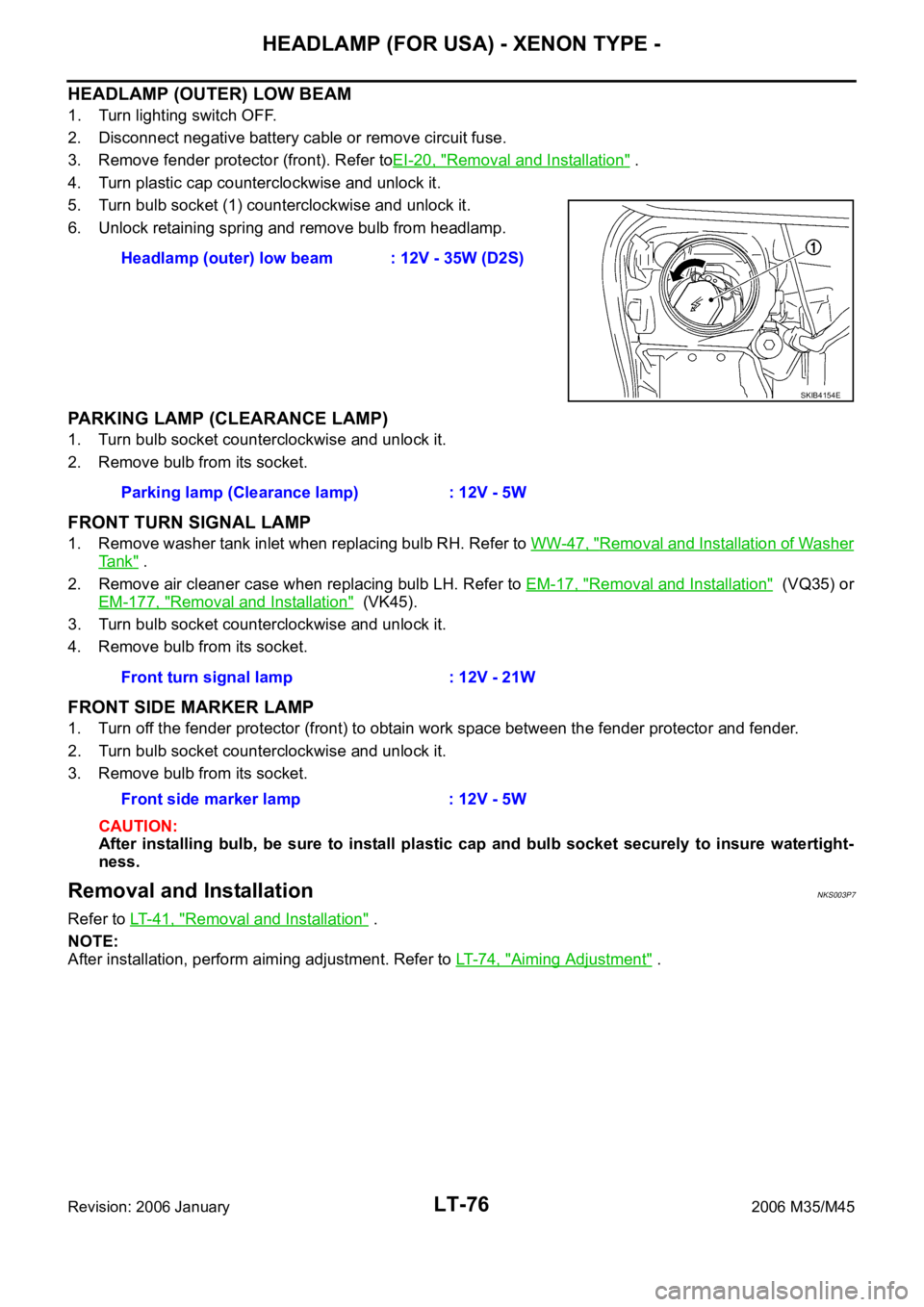
5. Turn bulb socket (1) counterclockwise and unlock it.
6. Unlock retaining spring and remove bulb from headlamp.
PARKING LAMP (CLEARANCE LAMP)
1. Turn bulb socket counterclockwise and unlock it.
2. Remove bulb from its socket.
FRONT TURN SIGNAL LAMP
1. Remove washer tank inlet when replacing bulb RH. Refer to WW-47, "Removal and Installation of Washer
Ta n k" .
2. Remove air cleaner case when replacing bulb LH. Refer to EM-17, "
Removal and Installation" (VQ35) or
EM-177, "
Removal and Installation" (VK45).
3. Turn bulb socket counterclockwise and unlock it.
4. Remove bulb from its socket.
FRONT SIDE MARKER LAMP
1. Turn off the fender protector (front) to obtain work space between the fender protector and fender.
2. Turn bulb socket counterclockwise and unlock it.
3. Remove bulb from its socket.
CAUTION:
After installing bulb, be sure to install plastic cap and bulb socket securely to insure watertight-
ness.
Removal and InstallationNKS003P7
Refer to LT-41, "Removal and Installation" .
NOTE:
After installation, perform aiming adjustment. Refer to LT- 7 4 , "
Aiming Adjustment" . Headlamp (outer) low beam : 12V - 35W (D2S)
SKIB4154E
Parking lamp (Clearance lamp) : 12V - 5W
Front turn signal lamp : 12V - 21W
Front side marker lamp : 12V - 5W
Page 4504 of 5621
HEADLAMP (FOR USA) - XENON TYPE -
LT-77
C
D
E
F
G
H
I
J
L
MA
B
LT
Revision: 2006 January2006 M35/M45
Disassembly and Assembly NKS003P8
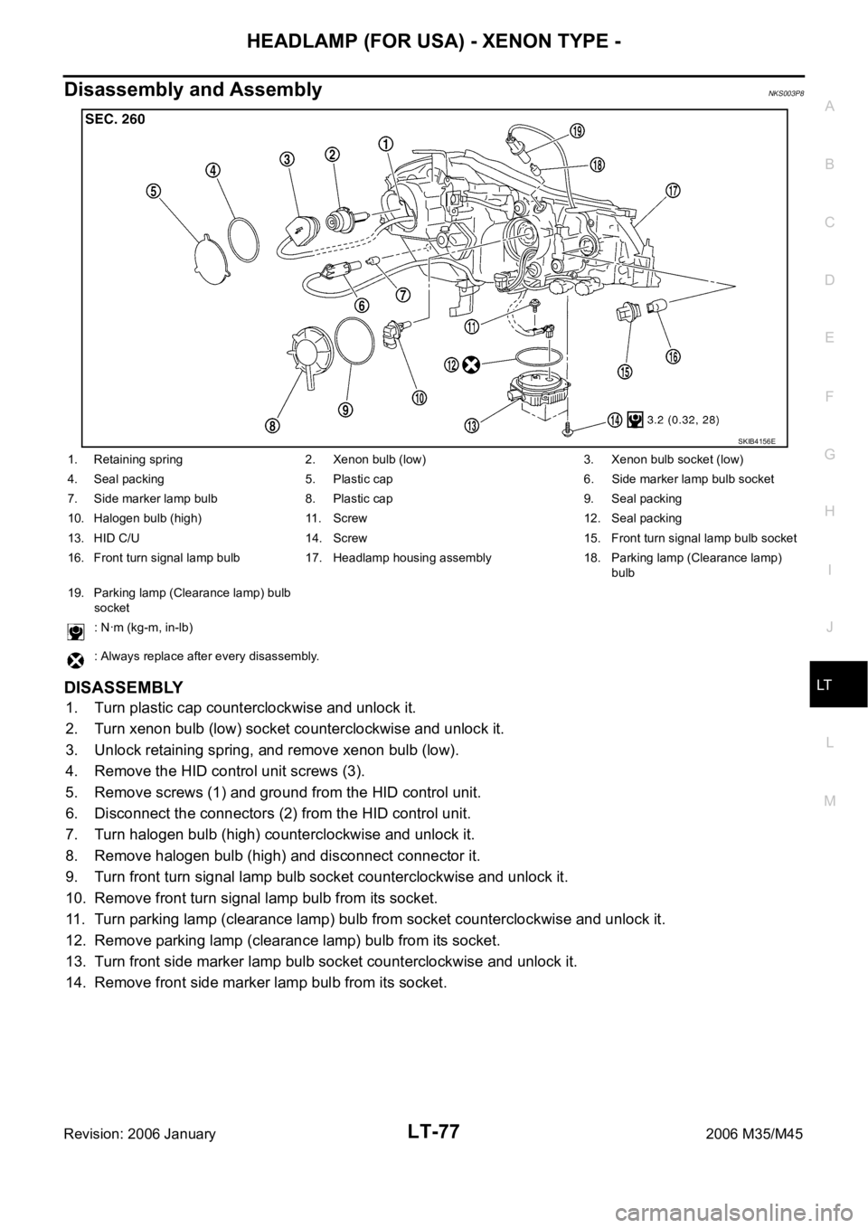
DISASSEMBLY
1. Turn plastic cap counterclockwise and unlock it.
2. Turn xenon bulb (low) socket counterclockwise and unlock it.
3. Unlock retaining spring, and remove xenon bulb (low).
4. Remove the HID control unit screws (3).
5. Remove screws (1) and ground from the HID control unit.
6. Disconnect the connectors (2) from the HID control unit.
7. Turn halogen bulb (high) counterclockwise and unlock it.
8. Remove halogen bulb (high) and disconnect connector it.
9. Turn front turn signal lamp bulb socket counterclockwise and unlock it.
10. Remove front turn signal lamp bulb from its socket.
11. Turn parking lamp (clearance lamp) bulb from socket counterclockwise and unlock it.
12. Remove parking lamp (clearance lamp) bulb from its socket.
13. Turn front side marker lamp bulb socket counterclockwise and unlock it.
14. Remove front side marker lamp bulb from its socket.
SKIB4156E
1. Retaining spring 2. Xenon bulb (low) 3. Xenon bulb socket (low)
4. Seal packing 5. Plastic cap 6. Side marker lamp bulb socket
7. Side marker lamp bulb 8. Plastic cap 9. Seal packing
10. Halogen bulb (high) 11. Screw 12. Seal packing
13. HID C/U 14. Screw 15. Front turn signal lamp bulb socket
16. Front turn signal lamp bulb 17. Headlamp housing assembly 18. Parking lamp (Clearance lamp)
bulb
19. Parking lamp (Clearance lamp) bulb
socket
: Nꞏm (kg-m, in-lb)
: Always replace after every disassembly.
Page 4507 of 5621

LT-80
HEADLAMP (FOR CANADA) - DAYTIME LIGHT SYSTEM -
Revision: 2006 January2006 M35/M45
OUTLINE
Power is supplied at all times
to headlamp high relay, located in IPDM E/R (intelligent power distribution module engine room) and
to headlamp low relay, located in IPDM E/R, from battery direct,
through 15A fuse (No. 71, located in IPDM E/R)
to CPU (central processing unit), located in IPDM E/R,
through 15A fuse (No. 78, located in IPDM E/R)
to CPU, located in IPDM E/R,
through 50A fusible link (letter F, located in fuse and fusible link block)
to BCM terminal 55,
through 10A fuse [No. 21, located in fuse block (J/B)]
to BCM terminal 42 and
to combination meter terminal 23,
through 10A fuse (No. 32, located in IPDM E/R)
to daytime light relay terminals 2 and 5,
through 10A fuse [No. 19, located in fuse block (J/B)]
to unified meter and A/C amp. terminal 54,
through 10A fuse [No. 22, located in fuse block (J/B)]
to key slot terminal 1.
When the ignition switch is in ON or START position, power is supplied
to CPU, located in IPDM E/R,
through 15A fuse [No. 1, located in fuse block (J/B)]
to BCM terminal 38,
through 10A fuse [No. 14, located in fuse block (J/B)]
to combination meter terminal 12,
through 10A fuse [No. 12, located in fuse block (J/B)]
to unified meter and A/C amp. terminal 53.
Ground is supplied
to BCM terminal 52
to combination meter terminals 9, 10, and 11
to unified meter and A/C amp. terminal 55 and 71
to push-button ignition switch (push switch) terminal 1
to key slot terminal 8
through grounds M16 and M70,
to IPDM E/R terminals 38 and 51
through grounds E22 and E43.
Page 4563 of 5621

LT-136
ACTIVE AFS
Revision: 2006 January2006 M35/M45
HEADLAMP AUTO AIMING
Headlamp auto aiming control automatically corrects vertical deviation of light axis that is brought by the
change of vehicle height with changing number of passenger and laden weight, and relieves dazzle to oncom-
ing vehicles.
AFS control unit determines the current vehicle conditions by each received signals, and sends commands to
the low beam headlamps to auto aiming. With the headlamps (HIGH/LOW) illuminated and engine running,
the low beam headlamps are operative by AFS control unit commands.
The height sensor is located on the left side of the rear suspension member and detects rear vehicle height
change by sensing the displacement of the rear suspension arm. And transmits a height sensor signal to the
AFS control unit.
With reference to the rear vehicle height under the empty condition, light axis of low beam with low rear vehi-
cle height is relatively higher than that with the empty condition. AFS control unit switches drive signal corrects
height of low beam axis to maintain height of light axis with empty condition.
Light axis of low beam with high rear vehicle height is relatively lower than that with empty condition. Light axis
of low beam with empty condition is set as upper limit of headlamp auto aiming control operation. Control to
correct deviation is not performed when light axis of low beam gets relatively higher than that with empty con-
dition. Timing of control is switched in accordance with driving conditions.
Headlamp auto aiming operation
*1: Included high beam illuminated
*2: Control timing of drive signal is switched by vehicle speed and accelerating/decelerating vehicle.
*3: Control is performed without regard to the condition of AFS switch. Headlamp auto aiming control function cannot be cancelled.
OUTLINE
Power is supplied
When the ignition switch is ON or START position, power is supplied
through 10A fuse [No.12, located in fuse block (J/B)]
to AFS control unit terminal 1
to front combination lamp LH and RH terminal 13
to AFS switch terminal 1.
Ground is supplied
to AFS control unit terminal 25
through grounds M16 and M70,
to front combination lamp LH and RH terminal 11
through grounds E22 and E43.
SKIB4707E
Operating range With 18-inch wheel (Reference value) With 19-inch wheel (Reference value) Vehicle height
A 0 mm (Standard position) 0 mm (Standard position) Unloaded vehicle position
B Approx. 200 mm (7.9 in) Approx.180 mm (7.1 in) Low
Low beam status Vehicle speed Engine speed AFS switch
Illuminated*
1Control switch by driving conditions*2While engine running
Irrespective*3
Page 4564 of 5621
ACTIVE AFS
LT-137
C
D
E
F
G
H
I
J
L
MA
B
LT
Revision: 2006 January2006 M35/M45
AFS OPERATION
When The Steering Wheel Is Turned To The Left
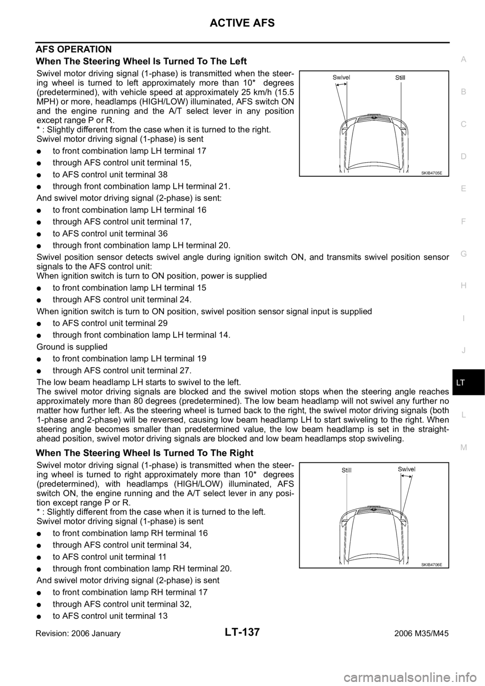
Swivel motor driving signal (1-phase) is transmitted when the steer-
ing wheel is turned to left approximately more than 10* degrees
(predetermined), with vehicle speed at approximately 25 km/h (15.5
MPH) or more, headlamps (HIGH/LOW) illuminated, AFS switch ON
and the engine running and the A/T select lever in any position
except range P or R.
* : Slightly different from the case when it is turned to the right.
Swivel motor driving signal (1-phase) is sent
to front combination lamp LH terminal 17
through AFS control unit terminal 15,
to AFS control unit terminal 38
through front combination lamp LH terminal 21.
And swivel motor driving signal (2-phase) is sent:
to front combination lamp LH terminal 16
through AFS control unit terminal 17,
to AFS control unit terminal 36
through front combination lamp LH terminal 20.
Swivel position sensor detects swivel angle during ignition switch ON, and transmits swivel position sensor
signals to the AFS control unit:
When ignition switch is turn to ON position, power is supplied
to front combination lamp LH terminal 15
through AFS control unit terminal 24.
When ignition switch is turn to ON position, swivel position sensor signal input is supplied
to AFS control unit terminal 29
through front combination lamp LH terminal 14.
Ground is supplied
to front combination lamp LH terminal 19
through AFS control unit terminal 27.
The low beam headlamp LH starts to swivel to the left.
The swivel motor driving signals are blocked and the swivel motion stops when the steering angle reaches
approximately more than 80 degrees (predetermined). The low beam headlamp will not swivel any further no
matter how further left. As the steering wheel is turned back to the right, the swivel motor driving signals (both
1-phase and 2-phase) will be reversed, causing low beam headlamp LH to start swiveling to the right. When
steering angle becomes smaller than predetermined value, the low beam headlamp is set in the straight-
ahead position, swivel motor driving signals are blocked and low beam headlamps stop swiveling.
When The Steering Wheel Is Turned To The Right
Swivel motor driving signal (1-phase) is transmitted when the steer-
ing wheel is turned to right approximately more than 10* degrees
(predetermined), with headlamps (HIGH/LOW) illuminated, AFS
switch ON, the engine running and the A/T select lever in any posi-
tion except range P or R.
* : Slightly different from the case when it is turned to the left.
Swivel motor driving signal (1-phase) is sent
to front combination lamp RH terminal 16
through AFS control unit terminal 34,
to AFS control unit terminal 11
through front combination lamp RH terminal 20.
And swivel motor driving signal (2-phase) is sent
to front combination lamp RH terminal 17
through AFS control unit terminal 32,
to AFS control unit terminal 13
SKIB4705E
SKIB4706E
Page 4565 of 5621
LT-138
ACTIVE AFS
Revision: 2006 January2006 M35/M45
through front combination lamp RH terminal 21.
Swivel position sensor detects swivel angle during ignition switch ON, and transmits swivel position sensor
signals to the AFS control unit:
When ignition switch is turn to ON position, power is supplied
to front combination lamp RH terminal 15
through AFS control unit terminal 4.
When ignition switch is turn to ON position, swivel position sensor input signal is supplied
to AFS control unit terminal 9
through front combination lamp RH terminal 14.
Ground is supplied
to front combination lamp RH terminal 19
through AFS control unit terminal 2.
The low beam headlamp RH starts to swivel to the right.
The swivel motor driving signals are blocked and the swivel motion stops when the steering angle reaches
approximately more than 80 degrees (predetermined). The low beam headlamp will not swivel any further no
matter how further right. As the steering wheel is turned back to the left, the swivel motor driving signals (both
1-phase and 2-phase) will be reversed, causing low beam headlamp RH to start swiveling to the left. When
steering angle becomes smaller than predetermined value, the low beam headlamp is set in the straight-
ahead position, swivel motor driving signals are blocked and low beam headlamps stop swiveling.
AFS OFF INDICATOR OPERATION
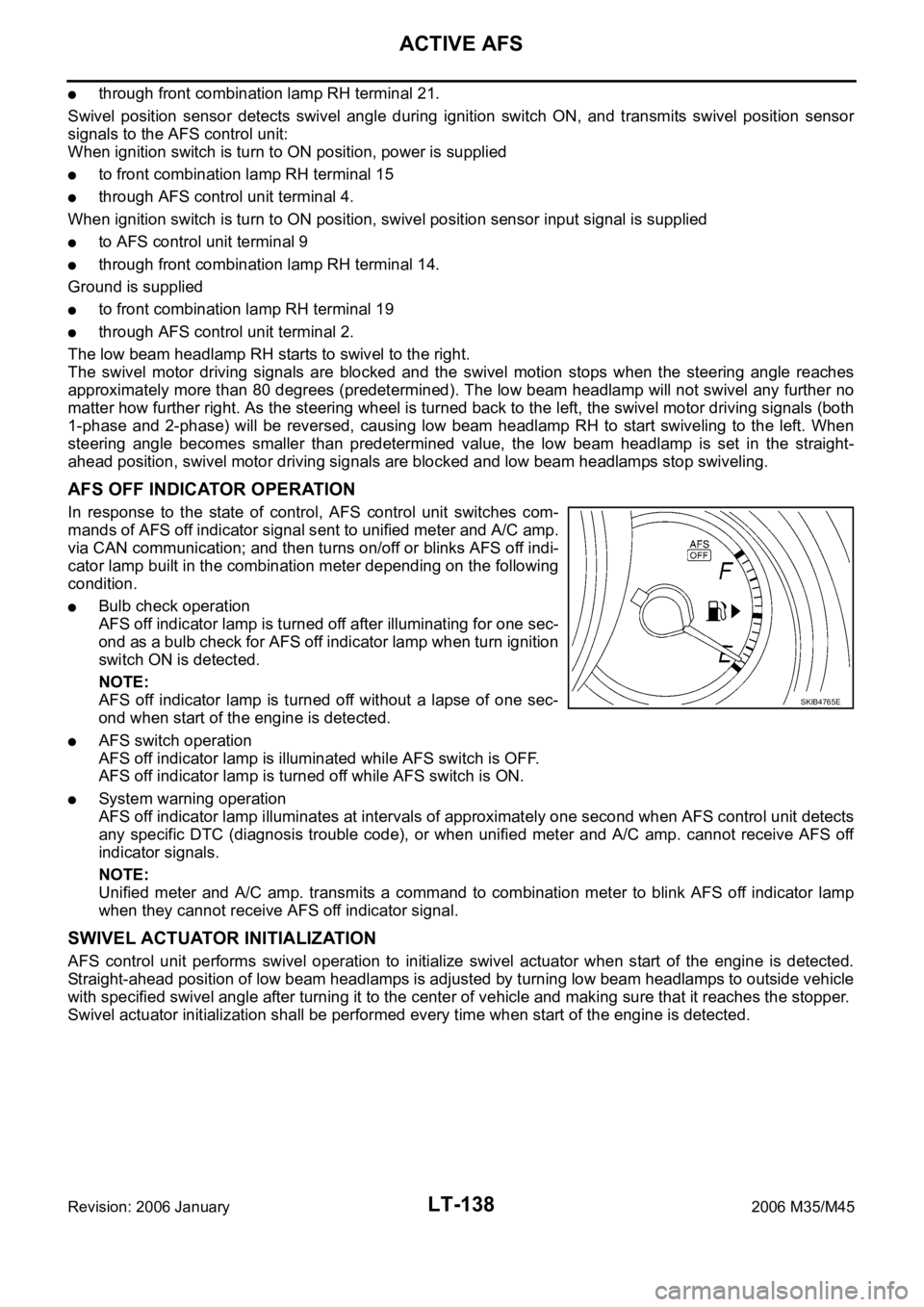
In response to the state of control, AFS control unit switches com-
mands of AFS off indicator signal sent to unified meter and A/C amp.
via CAN communication; and then turns on/off or blinks AFS off indi-
cator lamp built in the combination meter depending on the following
condition.
Bulb check operation
AFS off indicator lamp is turned off after illuminating for one sec-
ond as a bulb check for AFS off indicator lamp when turn ignition
switch ON is detected.
NOTE:
AFS off indicator lamp is turned off without a lapse of one sec-
ond when start of the engine is detected.
AFS switch operation
AFS off indicator lamp is illuminated while AFS switch is OFF.
AFS off indicator lamp is turned off while AFS switch is ON.
System warning operation
AFS off indicator lamp illuminates at intervals of approximately one second when AFS control unit detects
any specific DTC (diagnosis trouble code), or when unified meter and A/C amp. cannot receive AFS off
indicator signals.
NOTE:
Unified meter and A/C amp. transmits a command to combination meter to blink AFS off indicator lamp
when they cannot receive AFS off indicator signal.
SWIVEL ACTUATOR INITIALIZATION
AFS control unit performs swivel operation to initialize swivel actuator when start of the engine is detected.
Straight-ahead position of low beam headlamps is adjusted by turning low beam headlamps to outside vehicle
with specified swivel angle after turning it to the center of vehicle and making sure that it reaches the stopper.
Swivel actuator initialization shall be performed every time when start of the engine is detected.
SKIB4765E
Page 4621 of 5621

LT-194
FRONT FOG LAMP
Revision: 2006 January2006 M35/M45
OUTLINE
Power is supplied at all times
through 15A fuse (No. 88, located in IPDM E/R)
to front fog lamp relay, located in IPDM E/R,
through 15A fuse (No. 78, located in IPDM E/R)
to CPU, located in IPDM E/R,
through 15A fuse (No. 71, located in IPDM E/R)
to CPU, located in IPDM E/R,
through 50A fusible link (letter F, located in fuse fusible link and relay block)
to BCM terminal 55,
through 10A fuse [No. 21, located in fuse block (J/B)]
to BCM terminal 42, and
to combination meter terminal 23,
through 10A fuse [No. 19, located in fuse block (J/B)]
to unified meter and A/C amp. terminal 54,
through 10A fuse [No. 22, located in fuse block (J/B)]
to key slot terminal 1.
With the ignition switch in the ON or START position, power is supplied
to CPU, located in IPDM E/R,
through 15A fuse [No. 1, located in fuse block (J/B)]
to BCM terminal 38,
through 10A fuse [No. 14, located in fuse block (J/B)]
to combination meter terminal 12,
through 10A fuse [No. 12, located in fuse block (J/B)]
to unified meter and A/C amp. terminal 53.
With the ignition switch in the ACC or ON position, power is supplied
through 10A fuse [No. 6, located in fuse block (J/B)]
to BCM terminal 11.
Ground is supplied
to BCM terminal 52
to combination meter terminals 9, 10 and 11
to unified meter and A/C amp. terminals 55 and 71
to engine switch (push switch) terminal 1
to key slot terminal 8
through grounds M16 and M70,
to IPDM E/R terminals 38 and 51
through grounds E22 and E43.
Page 4637 of 5621
LT-210
FRONT FOG LAMP
Revision: 2006 January2006 M35/M45
Bulb ReplacementNKS003RI
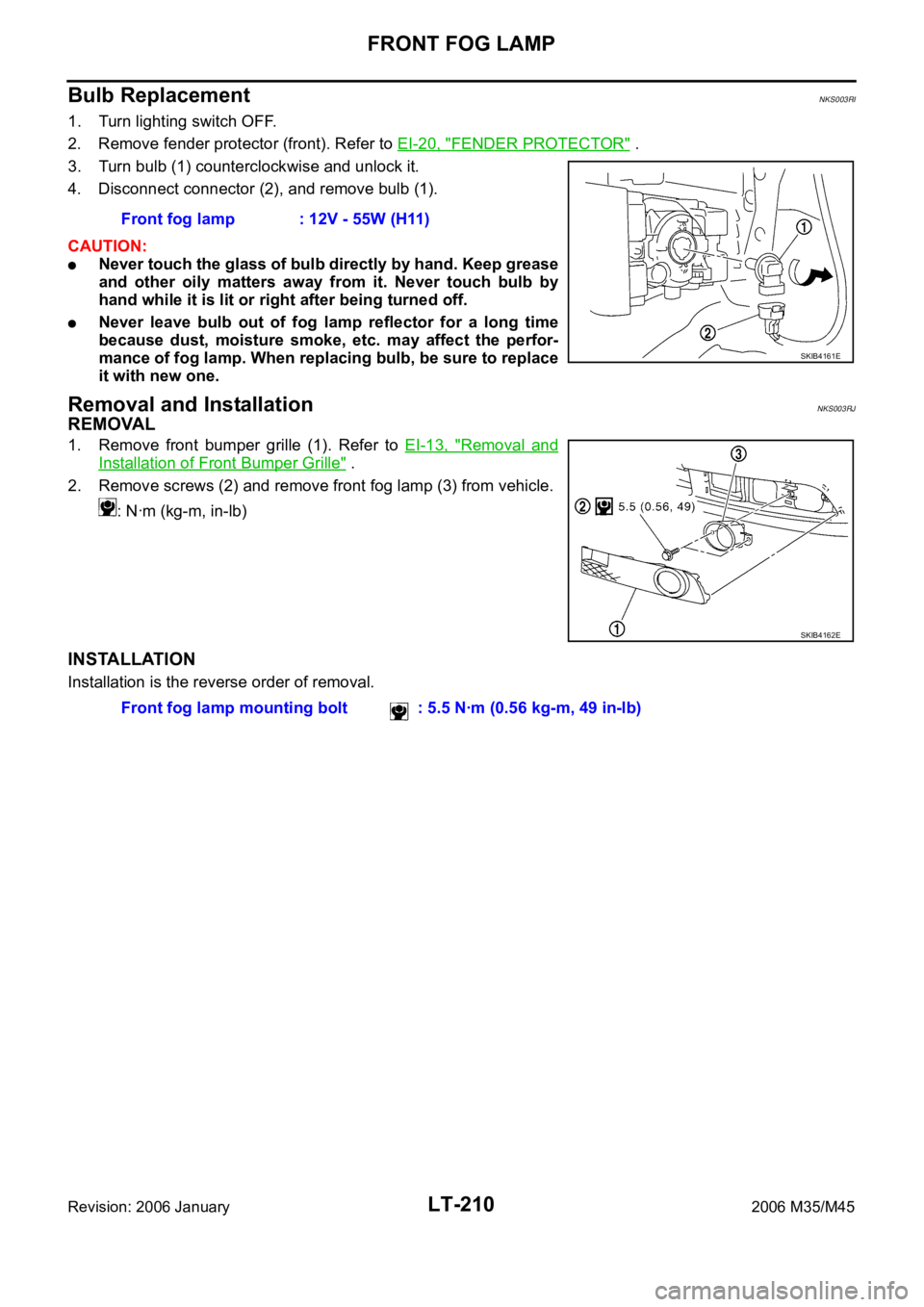
1. Turn lighting switch OFF.
2. Remove fender protector (front). Refer to EI-20, "
FENDER PROTECTOR" .
3. Turn bulb (1) counterclockwise and unlock it.
4. Disconnect connector (2), and remove bulb (1).
CAUTION:
Never touch the glass of bulb directly by hand. Keep grease
and other oily matters away from it. Never touch bulb by
hand while it is lit or right after being turned off.
Never leave bulb out of fog lamp reflector for a long time
because dust, moisture smoke, etc. may affect the perfor-
mance of fog lamp. When replacing bulb, be sure to replace
it with new one.
Removal and InstallationNKS003RJ
REMOVAL
1. Remove front bumper grille (1). Refer to EI-13, "Removal and
Installation of Front Bumper Grille" .
2. Remove screws (2) and remove front fog lamp (3) from vehicle.
: Nꞏm (kg-m, in-lb)
INSTALLATION
Installation is the reverse order of removal.Front fog lamp : 12V - 55W (H11)
SKIB4161E
SKIB4162E
Front fog lamp mounting bolt : 5.5 Nꞏm (0.56 kg-m, 49 in-lb)