2006 INFINITI M35 lock
[x] Cancel search: lockPage 4715 of 5621

LT-288
INTERIOR ROOM LAMP
Revision: 2006 January2006 M35/M45
Display Item List
NOTE:
This item is displayed, but cannot be monitored.
ACTIVE TEST (BATTERY SAVER)
Operation Procedure
1. Touch “BATTERY SAVER” on “SELECT TEST ITEM” screen.
2. Touch “ACTIVE TEST” on “SELECT DIAG MODE” screen.
3. Touch item to be tested and check operation of the selected item.
4. During the operation check, touching “BACK” deactivates the operation.
Display Item List
Monitor item Contents
IGN ON SW “ON/OFF”Displays “IGN ON position (ON)/OFF, ACC position (OFF)” judged from the ignition switch
signal.
ACC ON SW “ON/OFF”Displays “IGN ACC, ON position (ON)/OFF position (OFF)” status judged from the key
switch signal.
KEY ON SW “ON/OFF”Displays “Intelligent Key inserted into key slot (ON)/Intelligent Key removed from key slot
(OFF)” status judged from the key switch signal.
DOOR SW - DR “ON/OFF”Displays status of the driver door as judged from the driver door switch signal. (door is open:
ON/door is closed: OFF)
DOOR SW - AS “ON/OFF”Displays “door open (ON)/door closed (OFF)” status, determined from passenger door
switch signal.
DOOR SW - RR “ON/OFF”Displays “door open (ON)/door closed (OFF)” status, determined from rear door switch RH
signal.
DOOR SW - RL “ON/OFF”Displays “door open (ON)/door closed (OFF) ” status, determined from rear door switch LH
signal.
BACK DOOR SW
NOTE“OFF” —
CDL LOCK SW “ON/OFF”Displays “door locked (ON)/other (OFF) status, determined from central door lock switch
LOCK signal.
CDL UNLOCK SW “ON/OFF”Displays “door unlocked (ON)/other (OFF)” status, determined from central door lock switch
UNLOCK signal.
KEY CYL LK – SW “ON/OFF” Displays “door locked (ON)” status, determined from key cylinder switch in driver door.
KEY CYL UN – SW “ON/OFF” Displays “door unlocked (OFF)” status, determined from key cylinder switch in driver door.
I - KEY LOCK “ON/OFF” Displays “locked (ON)/other (OFF)” status, determined from lock signal.
I - KEY UNLOCK “ON/OFF” Displays “unlocked (ON)/other (OFF)” status, determined from unlock signal.
TRNK/HAT MNTR “ON/OFF”Displays “trunk open (ON)/trunk close (OFF)” status, determined from trunk room lamp
switch.
I - KEY DR UNLK “ON/OFF”Displays “ON” when only driver door is unlocked or “OFF” other cases by Intelligent Key or
any door request switch, determined from unlock signal.
I - KEY AS UNLK “ON/OFF”Displays “unlocked (ON)/locked (OFF)” states of passenger door by passenger side door
request switch, determined from unlock signal.
Test item Description
BATTERY SAVER Personal lamps and map lamps can be operated by any ON-OFF operations.
Page 4722 of 5621

ILLUMINATION
LT-295
C
D
E
F
G
H
I
J
L
MA
B
LT
Revision: 2006 January2006 M35/M45
ILLUMINATIONPFP:27545
System DescriptionNKS003TH
Control of the illumination lamps operation is dependent upon the position of the lighting switch (combination
switch). When the lighting switch is placed in the 1ST or 2ND position (or if the auto light system is activated)
the BCM (body control module) receives input signal requesting the illumination lamps to illuminate. This input
signal is communicated to the IPDM E/R (intelligent power distribution module engine room) across the CAN
communication lines. The CPU (central processing unit) located in the IPDM E/R controls the tail lamp relay
coil. This relay, when energized, directs power to the illumination lamps, which then illuminate.
OUTLINE
Power is supplied at all times
through 15A fuse (No. 71, located in IPDM E/R)
to tail lamp relay, located in IPDM E/R, and
to CPU located in IPDM E/R,
through 15A fuse (No. 78, located in IPDM E/R)
to CPU located in IPDM E/R,
through 50A fusible link (letter F, located in fuse, fusible link and relay block)
to BCM terminal 55,
through 10A fuse [No. 21, located in fuse block (J/B)]
to BCM terminal 42 and
to combination meter terminal 23,
through 10A fuse [No. 19, located in fuse block (J/B)]
to unified meter and A/C amp. terminal 54,
through 10A fuse [No. 22, located in fuse block (J/B)]
to intelligent key unit terminals 1, 41 and 57.
With the ignition switch in the ON or START position, power is supplied
through 15A fuse [No. 1, located in fuse block (J/B)]
to BCM terminal 38,
through 10A fuse [No. 14, located in fuse block (J/B)]
to combination meter terminal 12,
through 10A fuse [No. 12, located in fuse block (J/B)]
to unified meter and A/C amp. terminal 53 and
to rear sunshade cancel relay terminal 1.
With the ignition switch in the ACC or ON position, power is supplied
through 10A fuse [No. 6, located in fuse block (J/B)]
to BCM terminal 11
to unified meter and A/C amp. terminal 41 and
to combination meter terminal 2.
Ground is supplied
to BCM terminal 52
to unified meter and A/C amp. terminals 55 and 71
to combination meter terminals 9, 10, and 11
to Intelligent Key unit terminals 20, 40, 56 and 72, and
to illumination control switch terminal 3
through grounds M16 and M70,
to IPDM E/R terminals 38 and 51
through grounds E22 and E43.
Page 4723 of 5621

LT-296
ILLUMINATION
Revision: 2006 January2006 M35/M45
ILLUMINATION OPERATION BY LIGHTING SWITCH
With the lighting switch in the 1ST or 2ND position (or if the auto light system is activated), the BCM receives
input signal requesting the illumination lamps to illuminate. This input signal is communicated to the IPDM E/R
across the CAN communication lines. The CPU located in the IPDM E/R controls the tail lamp relay coil,
which, when energized, directs power
through IPDM E/R terminal 21
to combination meter terminal 13
to LDW switch (illumination) terminal 5 (with lane departure warning)
to VDC off switch (illumination) terminal 3
to trunk lid opener switch (illumination) terminal 3
to combination switch (spiral cable) terminal 24
to door mirror remote control switch (illumination) terminal 16
to AFS switch (illumination) terminal 5 (with AFS)
to rear sunshade front switch (illumination) terminal 5 (with rear control switch)
to A/T illumination terminal 1
to snow mode switch (illumination) terminal 5 (AWD models)
to rear control cancel switch (illumination) terminal 4 (with rear control switch)
to clock terminal 3
to multifunction switch terminal 3
to audio unit terminal 9
to DVD player terminal 18 (with DVD player)
to NAVI control unit terminal 61 (with navigation system)
to AV control unit terminal 61 (without navigation system)
to climate controlled seat switch driver side (illumination) terminal 7 (with climate controlled seat)
to climate controlled seat switch passenger side (illumination) terminal 7 (with climate controlled seat)
to ashtray illumination (rear LH) terminal 1
to ashtray illumination (rear RH) terminal 1
to illumination control switch terminal 1
to cigarette lighter socket (illumination) terminal 2
to map lamp (illumination) terminal 8
to power window main switch illumination terminal 1
to glove box lamp terminal 1
to rear control switch terminal 2
to rear power seat switch RH (illumination) terminal 4 (with rear control switch)
to rear heated seat switch RH (illumination) terminal 7 (with rear control switch)
to rear sunshade cancel relay terminal 6 (with rear control switch)
to automatic return cancel switch (illumination) terminal 4 (with rear control switch)
to rear power seat switch LH (illumination) terminal 4 (with rear control switch) and
to rear heated seat switch LH (illumination) terminal 7 (with rear control switch),
through Intelligent Key unit terminal 12
to push button ignition switch (illumination) terminal 3.
Ground is supplied
to combination meter terminal 14
to combination meter terminal 9, 10 and 11
to push button ignition switch (illumination) terminal 2
to LDW switch (illumination) terminal 4 (with lane departure warning)
to VDC off switch (illumination) terminal 4
to trunk lid opener switch (illumination) terminal 4
to combination switch (spiral cable) terminal 25
Page 4724 of 5621

ILLUMINATION
LT-297
C
D
E
F
G
H
I
J
L
MA
B
LT
Revision: 2006 January2006 M35/M45
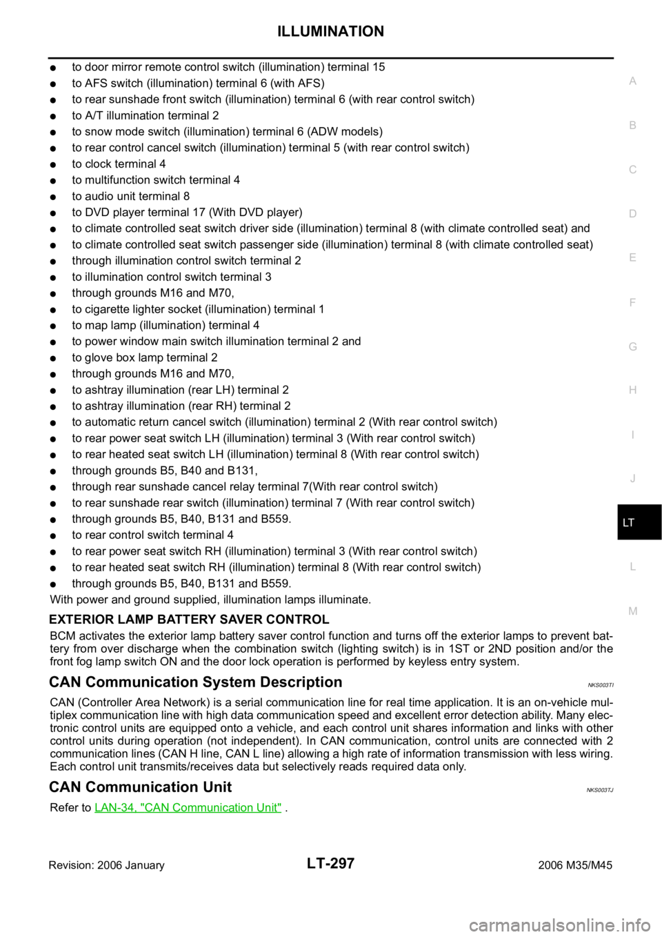
to door mirror remote control switch (illumination) terminal 15
to AFS switch (illumination) terminal 6 (with AFS)
to rear sunshade front switch (illumination) terminal 6 (with rear control switch)
to A/T illumination terminal 2
to snow mode switch (illumination) terminal 6 (ADW models)
to rear control cancel switch (illumination) terminal 5 (with rear control switch)
to clock terminal 4
to multifunction switch terminal 4
to audio unit terminal 8
to DVD player terminal 17 (With DVD player)
to climate controlled seat switch driver side (illumination) terminal 8 (with climate controlled seat) and
to climate controlled seat switch passenger side (illumination) terminal 8 (with climate controlled seat)
through illumination control switch terminal 2
to illumination control switch terminal 3
through grounds M16 and M70,
to cigarette lighter socket (illumination) terminal 1
to map lamp (illumination) terminal 4
to power window main switch illumination terminal 2 and
to glove box lamp terminal 2
through grounds M16 and M70,
to ashtray illumination (rear LH) terminal 2
to ashtray illumination (rear RH) terminal 2
to automatic return cancel switch (illumination) terminal 2 (With rear control switch)
to rear power seat switch LH (illumination) terminal 3 (With rear control switch)
to rear heated seat switch LH (illumination) terminal 8 (With rear control switch)
through grounds B5, B40 and B131,
through rear sunshade cancel relay terminal 7(With rear control switch)
to rear sunshade rear switch (illumination) terminal 7 (With rear control switch)
through grounds B5, B40, B131 and B559.
to rear control switch terminal 4
to rear power seat switch RH (illumination) terminal 3 (With rear control switch)
to rear heated seat switch RH (illumination) terminal 8 (With rear control switch)
through grounds B5, B40, B131 and B559.
With power and ground supplied, illumination lamps illuminate.
EXTERIOR LAMP BATTERY SAVER CONTROL
BCM activates the exterior lamp battery saver control function and turns off the exterior lamps to prevent bat-
tery from over discharge when the combination switch (lighting switch) is in 1ST or 2ND position and/or the
front fog lamp switch ON and the door lock operation is performed by keyless entry system.
CAN Communication System DescriptionNKS003TI
CAN (Controller Area Network) is a serial communication line for real time application. It is an on-vehicle mul-
tiplex communication line with high data communication speed and excellent error detection ability. Many elec-
tronic control units are equipped onto a vehicle, and each control unit shares information and links with other
control units during operation (not independent). In CAN communication, control units are connected with 2
communication lines (CAN H line, CAN L line) allowing a high rate of information transmission with less wiring.
Each control unit transmits/receives data but selectively reads required data only.
CAN Communication UnitNKS003TJ
Refer to LAN-34, "CAN Communication Unit" .
Page 4740 of 5621

ILLUMINATION
LT-313
C
D
E
F
G
H
I
J
L
MA
B
LT
Revision: 2006 January2006 M35/M45
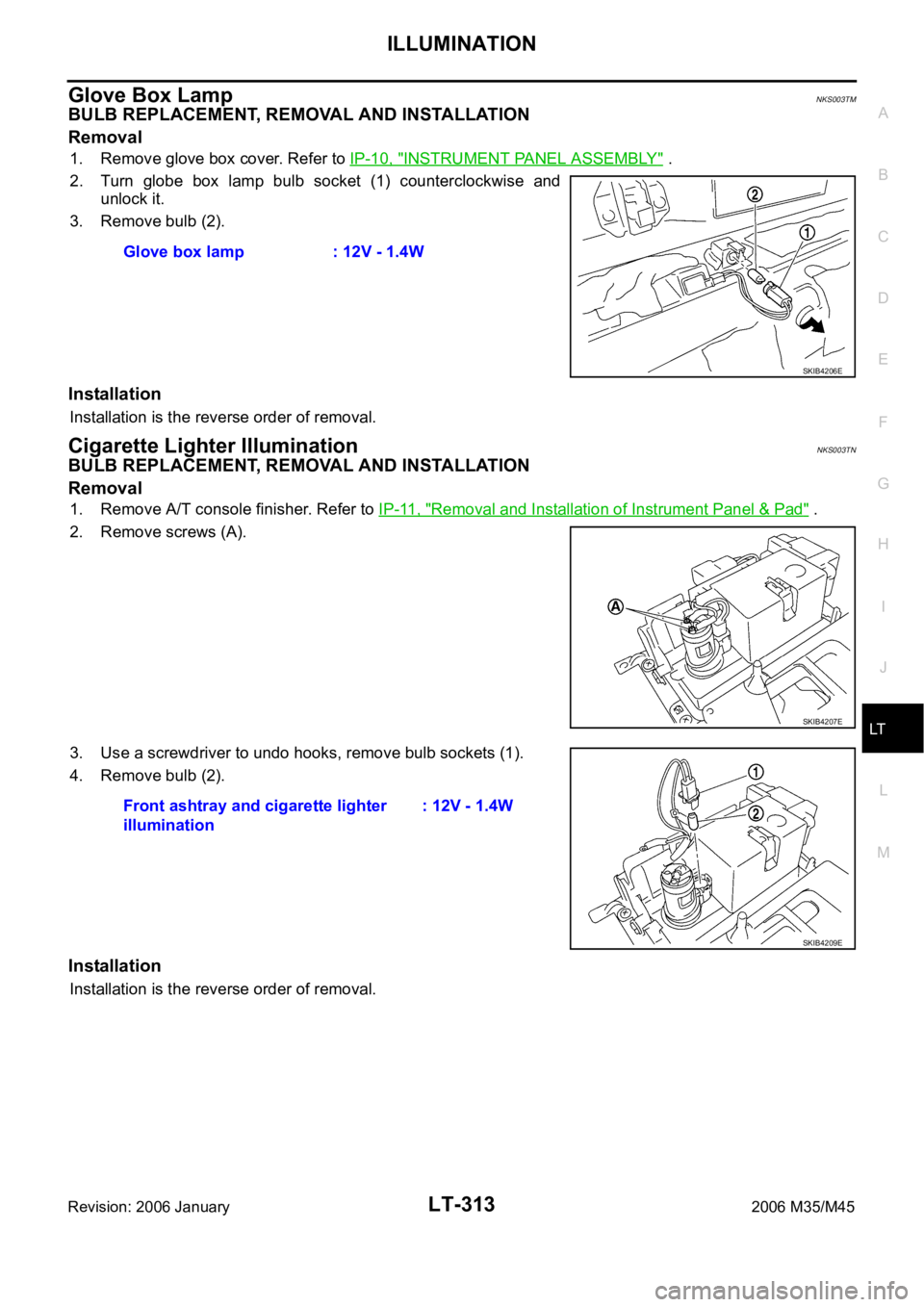
Glove Box LampNKS003TM
BULB REPLACEMENT, REMOVAL AND INSTALLATION
Removal
1. Remove glove box cover. Refer to IP-10, "INSTRUMENT PANEL ASSEMBLY" .
2. Turn globe box lamp bulb socket (1) counterclockwise and
unlock it.
3. Remove bulb (2).
Installation
Installation is the reverse order of removal.
Cigarette Lighter IlluminationNKS003TN
BULB REPLACEMENT, REMOVAL AND INSTALLATION
Removal
1. Remove A/T console finisher. Refer to IP-11, "Removal and Installation of Instrument Panel & Pad" .
2. Remove screws (A).
3. Use a screwdriver to undo hooks, remove bulb sockets (1).
4. Remove bulb (2).
Installation
Installation is the reverse order of removal.Glove box lamp : 12V - 1.4W
SKIB4206E
SKIB4207E
Front ashtray and cigarette lighter
illumination: 12V - 1.4W
SKIB4209E
Page 4741 of 5621

LT-314
ILLUMINATION
Revision: 2006 January2006 M35/M45
Front Ashtray IlluminationNKS003TO
BULB REPLACEMENT, REMOVAL AND INSTALLATION
Refer to LT- 3 1 4 , "Front Ashtray Illumination" .
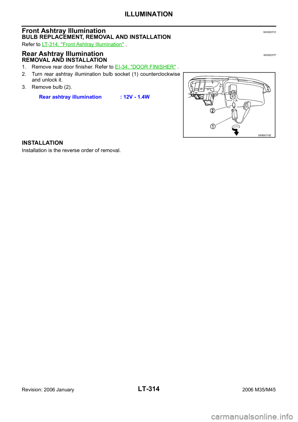
Rear Ashtray IlluminationNKS003TP
REMOVAL AND INSTALLATION
1. Remove rear door finisher. Refer to EI-34, "DOOR FINISHER" .
2. Turn rear ashtray illumination bulb socket (1) counterclockwise
and unlock it.
3. Remove bulb (2).
INSTALLATION
Installation is the reverse order of removal.Rear ashtray illumination : 12V - 1.4W
SKIB4210E
Page 4750 of 5621
![INFINITI M35 2006 Factory Service Manual ENGINE OIL
LU-7
[VQ35DE]
C
D
E
F
G
H
I
J
K
L
MA
LU
Revision: 2006 January2006 M35/M45
ENGINE OILPFP:KLA92
InspectionNBS004PW
ENGINE OIL LEVEL
NOTE:
Before starting engine, put vehicle horizontally and INFINITI M35 2006 Factory Service Manual ENGINE OIL
LU-7
[VQ35DE]
C
D
E
F
G
H
I
J
K
L
MA
LU
Revision: 2006 January2006 M35/M45
ENGINE OILPFP:KLA92
InspectionNBS004PW
ENGINE OIL LEVEL
NOTE:
Before starting engine, put vehicle horizontally and](/manual-img/42/57023/w960_57023-4749.png)
ENGINE OIL
LU-7
[VQ35DE]
C
D
E
F
G
H
I
J
K
L
MA
LU
Revision: 2006 January2006 M35/M45
ENGINE OILPFP:KLA92
InspectionNBS004PW
ENGINE OIL LEVEL
NOTE:
Before starting engine, put vehicle horizontally and check the engine oil level. If engine is already started, stop
it and allow 10 minutes before checking.
1. Pull out oil level gauge and wipe it clean.
2. Insert oil level gauge and make sure the engine oil level is within
the range shown in the figure.
3. If it is out of range, adjust it.
NOTE:
When checking the engine oil level, insert oil level gauge with its
tip aligned with oil level gauge guide on cylinder head. (In figure,
air cleaner case and air duct are removed.)
ENGINE OIL APPEARANCE
Check engine oil for white turbidity or heavy contamination.
If engine oil becomes turbid and white, it is highly probable that it is contaminated with engine coolant.
Repair or replace damaged parts.
ENGINE OIL LEAKAGE
Check for engine oil leakage around the following areas:
Oil pans (lower and upper)
Oil pan drain plug
Oil pressure switch
Oil filter
Oil filter bracket (AWD models)
Oil cooler
Water pump cover
Chain tensioner cover
Intake valve timing control cover and intake valve timing control solenoid valve
Mating surface between cylinder head and rocker cover
Mating surface between front timing chain case and rear timing chain case
Mating surface between rear timing chain case and cylinder head
Mating surface between rear timing chain case and cylinder block
Mating surface between rear timing chain case and oil pan (upper)
Mating surface between cylinder block and cylinder head
PBIC0249E
KBIA1343E
Page 4758 of 5621
![INFINITI M35 2006 Factory Service Manual OIL COOLER
LU-15
[VQ35DE]
C
D
E
F
G
H
I
J
K
L
MA
LU
Revision: 2006 January2006 M35/M45
AWD models
Removal and InstallationNBS004Q2
REMOVAL
WAR NING :
Be careful not to get burn yourself, as engine oil INFINITI M35 2006 Factory Service Manual OIL COOLER
LU-15
[VQ35DE]
C
D
E
F
G
H
I
J
K
L
MA
LU
Revision: 2006 January2006 M35/M45
AWD models
Removal and InstallationNBS004Q2
REMOVAL
WAR NING :
Be careful not to get burn yourself, as engine oil](/manual-img/42/57023/w960_57023-4757.png)
OIL COOLER
LU-15
[VQ35DE]
C
D
E
F
G
H
I
J
K
L
MA
LU
Revision: 2006 January2006 M35/M45
AWD models
Removal and InstallationNBS004Q2
REMOVAL
WAR NING :
Be careful not to get burn yourself, as engine oil and engine coolant may be hot.
NOTE:
When removing oil cooler only, step 2 is unnecessary.
1. Remove front engine undercover with power tool.
2. Drain engine coolant from radiator and cylinder block. Refer to CO-11, "
Changing Engine Coolant" and
EM-124, "
DISASSEMBLY" .
NOTE:
Perform this step when removing water pipes.
3. Disconnect water hoses from oil cooler.
When removing oil cooler only, pinching water hoses near oil cooler to prevent engine coolant from
spilling out.
Remaining engine coolant in piping will come out. Use a tray to collect it.
CAUTION:
Perform this step when the engine is cold.
Do not spill engine coolant on drive belts.
4. Using oil filter wrench [SST: KV10115801 (J38956)], remove oil filter. Refer to LU-10, "
OIL FILTER" .
CAUTION:
Do not spill engine oil on drive belts.
5. Remove connector bolt, and remove oil cooler.
PBIC3392E
1. Oil filter 2. Connector bolt 3. Oil cooler
4. O-ring 5. Relief valve 6. Oil filter bracket
7. Water hose 8. Water hose 9. Water pipe
10. Water hose