2006 INFINITI M35 wheel alignment
[x] Cancel search: wheel alignmentPage 5096 of 5621

FRONT LOWER LINK
RSU-15
C
D
F
G
H
I
J
K
L
MA
B
RSU
Revision: 2006 January2006 M35/M45
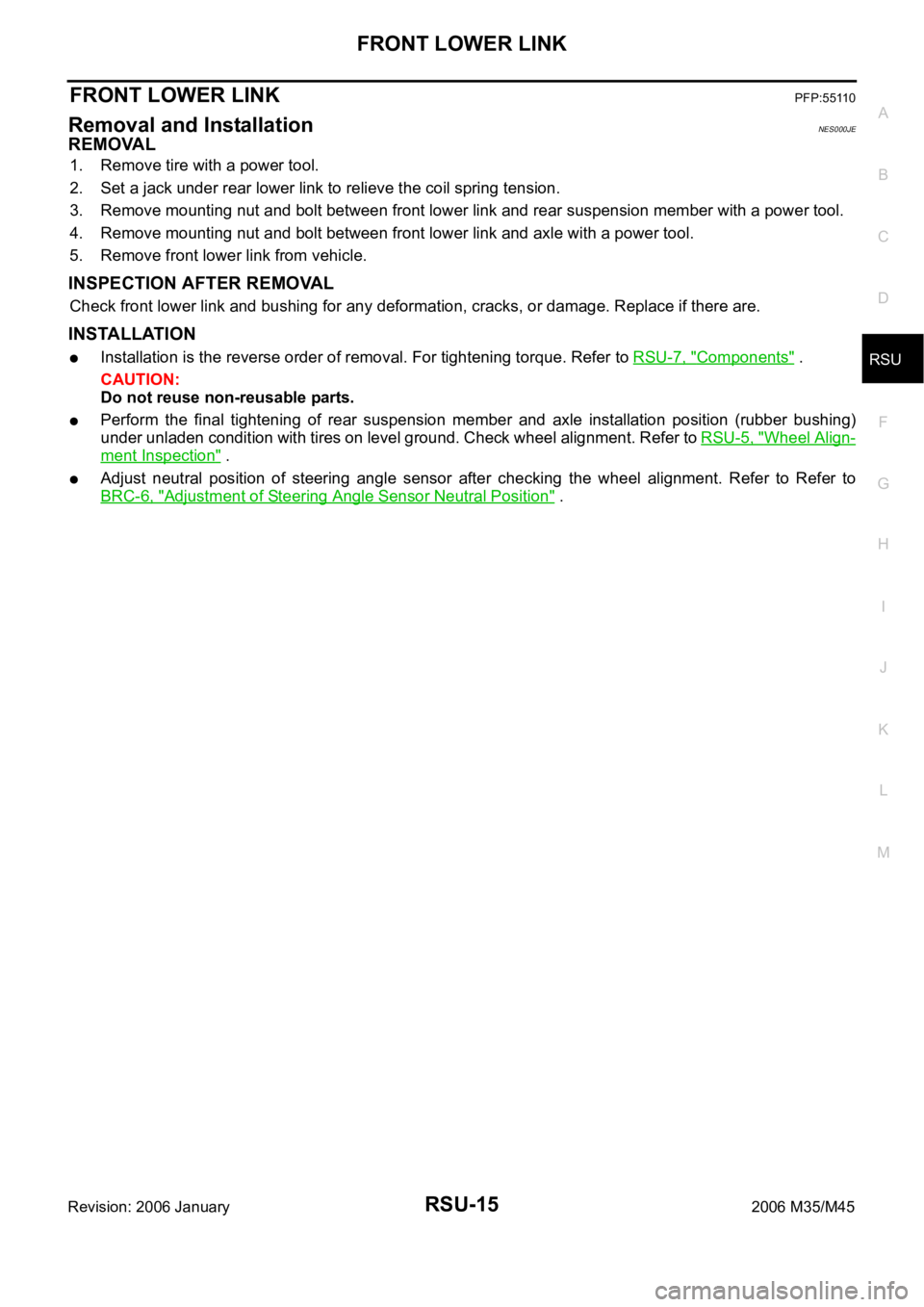
FRONT LOWER LINKPFP:55110
Removal and InstallationNES000JE
REMOVAL
1. Remove tire with a power tool.
2. Set a jack under rear lower link to relieve the coil spring tension.
3. Remove mounting nut and bolt between front lower link and rear suspension member with a power tool.
4. Remove mounting nut and bolt between front lower link and axle with a power tool.
5. Remove front lower link from vehicle.
INSPECTION AFTER REMOVAL
Check front lower link and bushing for any deformation, cracks, or damage. Replace if there are.
INSTALLATION
Installation is the reverse order of removal. For tightening torque. Refer to RSU-7, "Components" .
CAUTION:
Do not reuse non-reusable parts.
Perform the final tightening of rear suspension member and axle installation position (rubber bushing)
under unladen condition with tires on level ground. Check wheel alignment. Refer to RSU-5, "
Wheel Align-
ment Inspection" .
Adjust neutral position of steering angle sensor after checking the wheel alignment. Refer to Refer to
BRC-6, "
Adjustment of Steering Angle Sensor Neutral Position" .
Page 5097 of 5621

RSU-16
REAR LOWER LINK & COIL SPRING
Revision: 2006 January2006 M35/M45
REAR LOWER LINK & COIL SPRINGPFP:551B0
Removal and InstallationNES000JF
REMOVAL
1. Remove tire with a power tool.
2. Set a jack under rear lower link to relieve the coil spring tension.
3. Loosen mounting bolt and nut of rear lower link inside of suspension member, and then remove mounting
bolt and nut inside of axle with a power tool.
4. Slowly lower jack, then remove upper seat, coil spring and rubber sheet from rear lower link.
5. Remove mounting bolt and nut inside of suspension member to remove rear lower link with a power tool.
INSPECTION AFTER REMOVAL
Check rear lower link, bushing and coil spring for deformation, cracks, and damage. Replace rear lower link
and coil spring if there are.
INSTALLATION
Installation is the reverse order of removal. For tightening torque. Refer to RSU-7, "Components" .
CAUTION:
Do not reuse non-reusable parts.
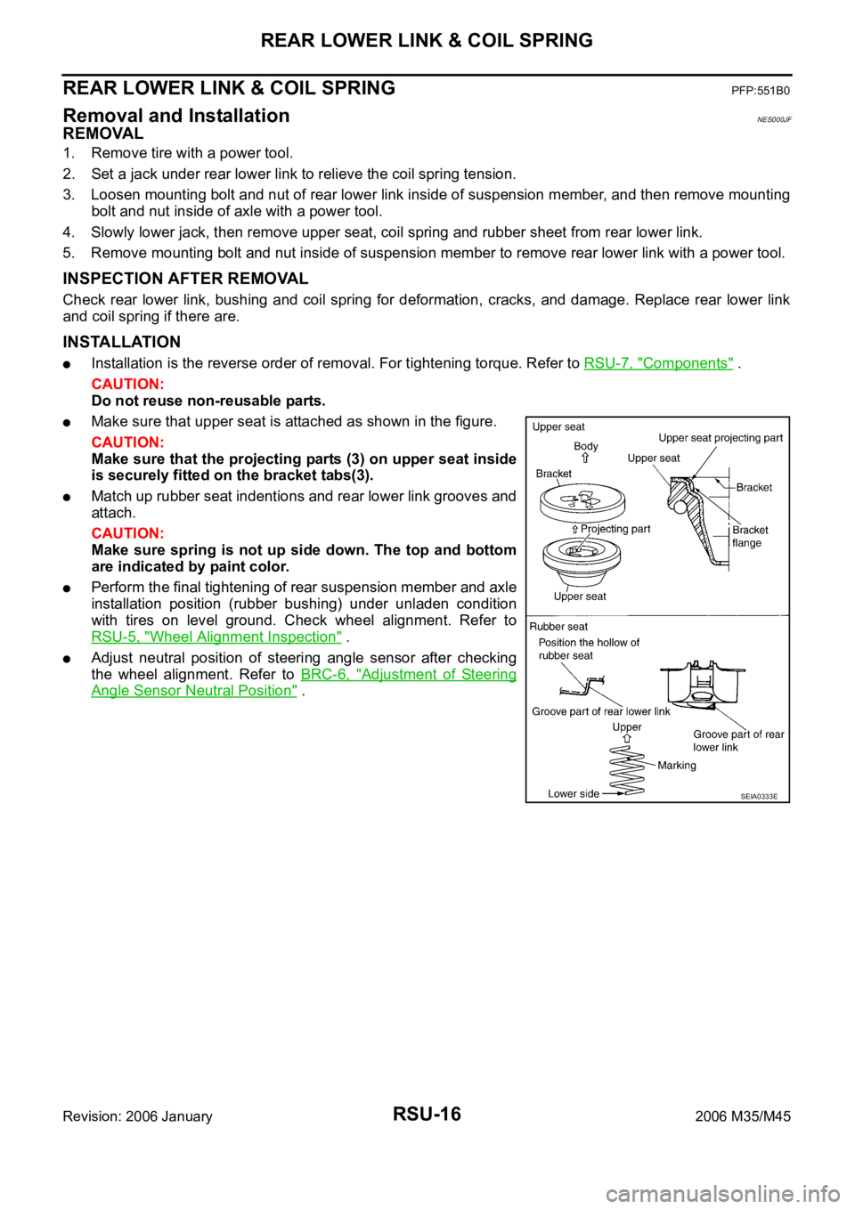
Make sure that upper seat is attached as shown in the figure.
CAUTION:
Make sure that the projecting parts (3) on upper seat inside
is securely fitted on the bracket tabs(3).
Match up rubber seat indentions and rear lower link grooves and
attach.
CAUTION:
Make sure spring is not up side down. The top and bottom
are indicated by paint color.
Perform the final tightening of rear suspension member and axle
installation position (rubber bushing) under unladen condition
with tires on level ground. Check wheel alignment. Refer to
RSU-5, "
Wheel Alignment Inspection" .
Adjust neutral position of steering angle sensor after checking
the wheel alignment. Refer to BRC-6, "
Adjustment of Steering
Angle Sensor Neutral Position" .
SEIA0333E
Page 5099 of 5621

RSU-18
SERVICE DATA
Revision: 2006 January2006 M35/M45
SERVICE DATAPFP:00030
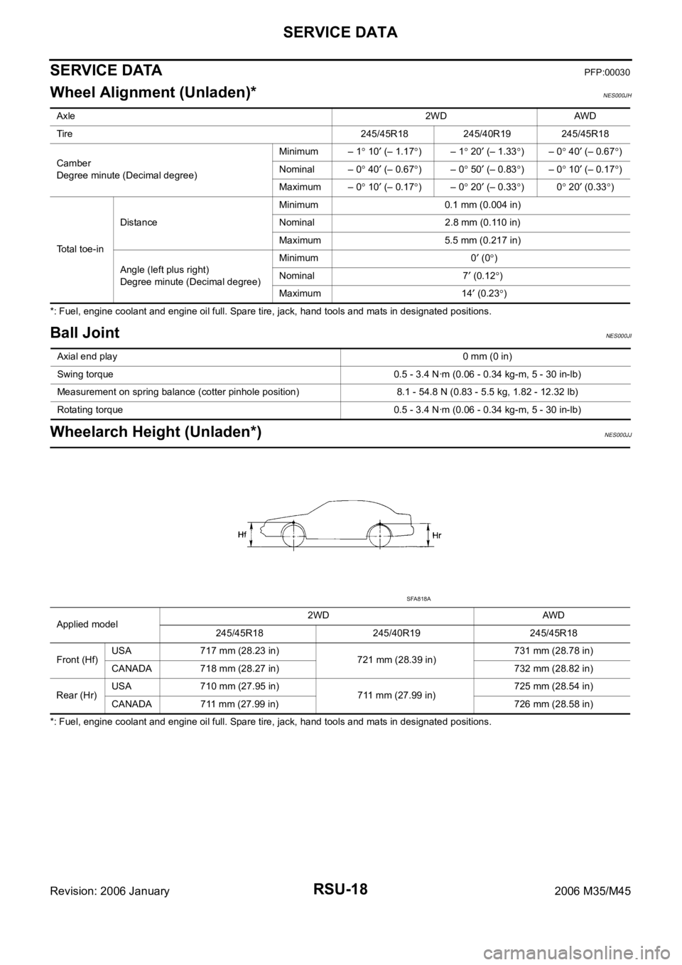
Wheel Alignment (Unladen)*NES000JH
*: Fuel, engine coolant and engine oil full. Spare tire, jack, hand tools and mats in designated positions.
Ball JointNES000JI
Wheelarch Height (Unladen*)NES000JJ
*: Fuel, engine coolant and engine oil full. Spare tire, jack, hand tools and mats in designated positions. Axle2WD AWD
Tire 245/45R18 245/40R19 245/45R18
Camber
Degree minute (Decimal degree)Minimum – 1
10 (– 1.17)– 1 20 (– 1.33)– 0 40 (– 0.67)
Nominal – 0
40 (– 0.67)– 0 50 (– 0.83)– 0 10 (– 0.17)
Maximum – 0
10 (– 0.17)– 0 20 (– 0.33)0 20 (0.33)
Total toe-inDistanceMinimum 0.1 mm (0.004 in)
Nominal 2.8 mm (0.110 in)
Maximum 5.5 mm (0.217 in)
Angle (left plus right)
Degree minute (Decimal degree)Minimum 0
(0)
Nominal 7
(0.12)
Maximum 14
(0.23)
Axial end play0 mm (0 in)
Swing torque 0.5 - 3.4 Nꞏm (0.06 - 0.34 kg-m, 5 - 30 in-lb)
Measurement on spring balance (cotter pinhole position) 8.1 - 54.8 N (0.83 - 5.5 kg, 1.82 - 12.32 lb)
Rotating torque 0.5 - 3.4 Nꞏm (0.06 - 0.34 kg-m, 5 - 30 in-lb)
Applied model2WD AWD
245/45R18 245/40R19 245/45R18
Front (Hf)USA 717 mm (28.23 in)
721 mm (28.39 in)731 mm (28.78 in)
CANADA 718 mm (28.27 in) 732 mm (28.82 in)
Rear (Hr)USA 710 mm (27.95 in)
711 mm (27.99 in)725 mm (28.54 in)
CANADA 711 mm (27.99 in) 726 mm (28.58 in)
SFA818A
Page 5424 of 5621
![INFINITI M35 2006 Factory Service Manual TROUBLE DIAGNOSIS
STC-9
[EPS]
C
D
E
F
H
I
J
K
L
MA
B
STC
Revision: 2006 January2006 M35/M45
For Fast and Accurate Trouble DiagnosisNGS000E1
Check the following items with the vehicle stopped
Is air pr INFINITI M35 2006 Factory Service Manual TROUBLE DIAGNOSIS
STC-9
[EPS]
C
D
E
F
H
I
J
K
L
MA
B
STC
Revision: 2006 January2006 M35/M45
For Fast and Accurate Trouble DiagnosisNGS000E1
Check the following items with the vehicle stopped
Is air pr](/manual-img/42/57023/w960_57023-5423.png)
TROUBLE DIAGNOSIS
STC-9
[EPS]
C
D
E
F
H
I
J
K
L
MA
B
STC
Revision: 2006 January2006 M35/M45
For Fast and Accurate Trouble DiagnosisNGS000E1
Check the following items with the vehicle stopped
Is air pressure and size of tires proper?
Is the specified part used for the steering wheel?
Is control unit a genuine part?
Are there any fluid leakage from steering gear assembly, power steering oil pump, and hydraulic pipes,
etc? Refer to PS-8, "
POWER STEERING FLUID" .
Is the fluid level proper? Refer to PS-8, "POWER STEERING FLUID" .
Is the wheel alignment adjusted properly? Refer to FSU-19, "SERVICE DATA AND SPECIFICATIONS
(SDS)" (2WD), FSU-36, "SERVICE DATA AND SPECIFICATIONS (SDS)" (AWD).
Are there any damage or modification to suspension or body resulting in increased weight or altered
ground clearance?
Check each link installation condition of suspension and axle.
Check each connector connection condition.
Check the following items while driving the vehicle
Check conditions when the malfunction occurred (5W 1H).
Is the engine condition normal?
Basic InspectionNGS000E2
POWER SUPPLY CIRCUIT TERMINAL LOOSENESS AND BATTERY
Check battery terminals for looseness on both positive and negative ones and ground connection. Also make
sure that battery voltage does not drop.
Inspection: Power Steering Control Unit Power Supply Circuit and GroundNGS000E3
1. CHECK POWER STEERING CONTROL UNIT CONNECTOR
Turn ignition switch OFF, disconnect power steering control unit harness connector, and check terminal for
deformation, disconnection, looseness, etc.
OK or NG
OK >> GO TO 2.
NG >> Connector terminal connection is loose, damaged, open, or shorted. Repair or replace the termi-
nal.
2. CHECK POWER STEERING CONTROL UNIT GROUND CIRCUIT
Disconnect power steering control unit harness connector M8, and
then check continuity between power steering control unit harness
connector M8 and ground.
OK or NG
OK >> GO TO 3.
NG >> Ground circuit open or shorted. Repair or replace any
inoperative parts. Terminal 2 – Ground : Continuity exist.
SGIA1231E
Page 5447 of 5621
![INFINITI M35 2006 Factory Service Manual STC-32
[RAS]
TROUBLE DIAGNOSIS
Revision: 2006 January2006 M35/M45
For Fast and Accurate Trouble DiagnosisNGS000EN
Check the following items with the vehicle stopped
Is air pressure and size of tires p INFINITI M35 2006 Factory Service Manual STC-32
[RAS]
TROUBLE DIAGNOSIS
Revision: 2006 January2006 M35/M45
For Fast and Accurate Trouble DiagnosisNGS000EN
Check the following items with the vehicle stopped
Is air pressure and size of tires p](/manual-img/42/57023/w960_57023-5446.png)
STC-32
[RAS]
TROUBLE DIAGNOSIS
Revision: 2006 January2006 M35/M45
For Fast and Accurate Trouble DiagnosisNGS000EN
Check the following items with the vehicle stopped
Is air pressure and size of tires proper?
Is the specified part used for the steering wheel?
Is control unit a genuine part?
Are there any fluid leakage from steering gear assembly, power steering oil pump, and hydraulic pipes,
etc? Refer to PS-8, "
POWER STEERING FLUID" .
Is the fluid level proper? Refer to PS-8, "POWER STEERING FLUID" .
Is the wheel alignment is adjusted properly? Refer to FSU-19, "SERVICE DATA AND SPECIFICATIONS
(SDS)" (2WD), FSU-36, "SERVICE DATA AND SPECIFICATIONS (SDS)" (AWD).
Are there any damage or modification to suspension or body resulting in increased weight or altered
ground clearance?
Check each link installation condition of suspension and axle.
Is the battery voltage proper?
Check each connector connection condition.
Check the following items while driving the vehicle
Conditions when the error occurred (5W 1H).
Is the engine is normal?
Basic InspectionNGS000EO
BASIC INSPECTION 1: POWER SUPPLY CIRCUIT TERMINAL LOOSENESS AND BATTERY
Check battery terminals for looseness on both positive and negative ones and ground connection. Also make
sure that battery voltage does not drop.
BASIC INSPECTION 2: RAS WARNING LAMP INSPECTION
1. Make sure RAS warning lamp turns on when ignition switch is turned ON.
If it does not turn on, refer to STC-33, "Trouble Diagnosis Chart" .
2. Make sure that RAS warning lamp turns off when the engine is started after ignition switch is turned ON. If
it does not turn off, perform self-diagnosis. Refer to STC-28, "
SELF-DIAG RESULT MODE" .
3. Always erase DTC memory after completing self-diagnosis. Refer to STC-29, "
How to Erase Self-Diag-
nostic Results" .
BASIC INSPECTION 3: RAS CONTROL UNIT POWER SUPPLY CIRCUIT AND GROUND CIR-
CUIT INSPECTION
1. CHECK RAS CONTROL UNIT CONNECTOR
Turn ignition switch OFF, disconnect RAS control unit harness connector, and check terminal for deformation,
disconnection, looseness, etc.
OK or NG
OK >> GO TO 2.
NG >> Poor connection of connector terminal. Repair or replace the terminal.
2. CHECK RAS CONTROL UNIT GROUND CIRCUIT
1. Disconnect RAS control unit harness connector B127, and then
check continuity between RAS control unit harness connector
B127 and ground.
OK or NG
OK >> GO TO 3.
NG >> Ground circuit open or shorted. Repair or replace any
inoperative parts. Terminal 34 – Ground : Continuity
SGIA1244E