2006 INFINITI M35 service indicator
[x] Cancel search: service indicatorPage 3646 of 5621
 ....... EC-189,
EC-911
Heated oxygen sensor 2 heater (bank 2) .......")
IDX-5
A
C
D
E
F
G
H
I
J
K
L B
IDX
ALPHABETICAL INDEX
EC-310, EC-1009, EC-1020, EC-1033
Heated oxygen sensor 2 heater (bank 1) ....... EC-189,
EC-911
Heated oxygen sensor 2 heater (bank 2) ....... EC-189,
EC-911
Heated seat ..................................................... SE-143
Heater and cooling unit (Heater core) ........... ATC-135
HFC134a (R134a) system precaution ............... ATC-6
HFC134a (R134a) system service procedure ATC-151
HFC134a (R134a) system service tools .......... ATC-17
HFC134a system service equipment precaution ..........
ATC-13
High and low reverse clutch solenoid valve .... AT-159,
AT-161
Hood ................................................................... BL-15
Horn ................................................................. WW-53
HORN - Wiring diagram ................................... WW-53
How to erase DTC for OBD system ..... EC-67, EC-778
HSEAT - Wiring diagram ................................. SE-146
I
IATS - Wiring diagram ....................... EC-223
, EC-945
ICC - Wiring diagram ....................................... ACS-21
ICC/BS - Wiring diagram ................. EC-578, EC-1304
ICC/SW - Wiring diagram ................ EC-563, EC-1289
ICCBOF - Wiring diagram ................ EC-700, EC-1442
Idle air volume learning ....................... EC-96, EC-807
Idle mixture ratio .................................. EC-84, EC-795
Idle speed .............................. EC-77, EC-788, EC-793
Idle speed control (ISC) .... EC-483, EC-485, EC-1202,
EC-1204
Ignition coil ....................................... EC-666, EC-1407
Ignition coil(VK45DE) ...................................... EM-190
Ignition coil(VQ35DE) ........................................ EM-42
Ignition control system ..................... EC-666, EC-1407
Ignition timing ........................ EC-77, EC-788, EC-793
IGNSYS - Wiring diagram ................ EC-667, EC-1408
Illumination ....................................................... LT-295
Illumination control ................. LT-291, LT-292, LT-293
In vehicle sensor ........................... ATC-116, ATC-127
INJECT - Wiring diagram ................. EC-680, EC-1421
Injector ............................................................. EC-679
Input clutch solenoid valve ................. AT-147, AT-149
Instrument panel .................................................. IP-10
Intake air temperature sensor ........... EC-221, EC-241,
EC-943
, EC-964
Intake door control linkage adjustment ............ ATC-88
Intake door motor ........................... ATC-86, ATC-133
Intake manifold collector(VQ35DE) ................... EM-19
Intake manifold(VK45DE) ................................ EM-179
Intake manifold(VQ35DE) .................................. EM-24
Intake sensor ................................ ATC-122, ATC-129
Intake valve timing control (Bank 1) .. EC-178, EC-891
Intake valve timing control (Bank 2) .. EC-178, EC-891
Intake valve timing control position sensor (Bank 1) ....
EC-1228
Intake valve timing control position sensor (Bank 2) ....
EC-1228
Intake valve timing control solenoid valve (Bank 1) ......
EC-197
, EC-920
Intake valve timing control solenoid valve (Bank 2) ......
EC-197
, EC-920
Integrated homelink transmitter ....................... BL-281
Intelligent cruise control (ICC) system .............. ACS-6
Interior ................................................................. EI-37
Interior lamp ...................................................... LT-267
IPDM (Intelligent power distribution module engine
room) ................................................................. PG-18
IVCB1 - Wiring diagram ..................... EC-198, EC-921
IVCB2 - Wiring diagram ..................... EC-200, EC-923
IVCSB1 - Wiring diagram ............................... EC-1229
IVCSB2 - Wiring diagram ............................... EC-1231
IVIS (Infiniti vehicle immobilizer system) precautions ...
GI-3
IVTB1 - Wiring diagram ................................... EC-894
IVTB2 - Wiring diagram ................................... EC-896
K
Knock sensor (KS) ........................... EC-371
, EC-1094
KS - Wiring diagram ......................... EC-372, EC-1095
L
LAN system circuit ........................................... ATC-70
Lane Departure Warning System ....................... DI-78
Laser beam aiming adjustment ....................... ACS-13
Latch (lower anchors and tether for children) system ...
SB-36
LDW .................................................................... DI-78
LDW - Wiring Diagram ........................................ DI-89
License lamp ..................................................... LT-249
Line pressure solenoid valve ........................... AT-130
Line pressure test (A/T) ..................................... AT-55
Liquid gasket application ......................... EM-7, LU-22
Liquid gasket application(VQ35DE) ........... LU-3, CO-3
Location of electrical units ................................. PG-96
Low coast brake solenoid valve ......... AT-163, AT-165
Low tire pressure warning system ...................... WT-9
Lubricant (R134a) A/C ..................................... ATC-26
Lubrication circuit (engine)(VK45DE) ................ LU-24
Lubrication circuit (engine)(VQ35DE) .................. LU-5
Lubrication oil A/C .......................................... ATC-174
M
MAFS - Wiring diagram ..... EC-208
, EC-216, EC-930,
EC-938
Magnet clutch .................................................. ATC-94
MAIN - Wiring diagram ........ EC-166, EC-879, AT-180
Maintenance (engine)(VQ35DE) ...................... MA-14
Major overhaul (Final drive) .............. FFD-15, RFD-18
Major overhaul (Transfer) .................................. TF-45
Malfunction indicator lamp (MIL) .......... EC-69, EC-780
Manual mode switch ........................................ AT-167
Mass air flow sensor (MAFS) ............ EC-205, EC-214,
EC-927
, EC-936
Page 4428 of 5621

LT-1
LIGHTING SYSTEM
K ELECTRICAL
CONTENTS
C
D
E
F
G
H
I
J
L
M
SECTION LT
A
B
LT
Revision: 2006 January2006 M35/M45
LIGHTING SYSTEM
PRECAUTIONS .......................................................... 6
Precautions for Supplemental Restraint System
(SRS) “AIR BAG” and “SEAT BELT PRE-TEN-
SIONER” .................................................................. 6
General Precautions for Service Operations ............ 7
HEADLAMP (FOR USA) - CONVENTIONAL TYPE - ..... 8
Component Parts and Harness Connector Location ..... 8
System Description .................................................. 8
OUTLINE ............................................................... 9
HEADLAMP OPERATION .................................. 10
COMBINATION SWITCH READING FUNCTION .... 11
EXTERIOR LAMP BATTERY SAVER CONTROL .... 11
AUTO LIGHT OPERATION .................................. 11
CAN Communication System Description ............... 11
CAN Communication Unit ....................................... 11
Schematic .............................................................. 12
Wiring Diagram — H/LAMP — ............................... 13
Terminals and Reference Values for BCM ............. 18
Terminals and Reference Values for IPDM E/R ..... 20
How to Perform Trouble Diagnoses ....................... 20
Preliminary Check .................................................. 20
CHECK POWER SUPPLY AND GROUND CIR-
CUIT .................................................................... 20
CONSULT-II Functions (BCM) ............................... 22
CONSULT-II BASIC OPERATION ....................... 22
DATA MONITOR ................................................. 23
ACTIVE TEST ..................................................... 24
CONSULT-II Functions (IPDM E/R) ....................... 25
CONSULT-II BASIC OPERATION ....................... 25
DATA MONITOR ................................................. 26
ACTIVE TEST ..................................................... 26
Headlamp High Beam Does Not Illuminate (Both
Sides) ..................................................................... 27
Headlamp High Beam Does Not Illuminate (One
Side) ....................................................................... 30
High Beam Indicator Lamp Does Not Illuminate .... 31
Headlamp Low Beam Does Not Illuminate (Both
Sides) ..................................................................... 32
Headlamp Low Beam Does Not Illuminate (One
Side) ....................................................................... 35Headlamps Do Not Turn OFF ................................. 37
Aiming Adjustment .................................................. 38
PREPARATION BEFORE ADJUSTING .............. 38
LOW BEAM AND HIGH BEAM ........................... 38
ADJUSTMENT USING AN ADJUSTMENT
SCREEN (LIGHT/DARK BORDERLINE) ............ 39
Bulb Replacement .................................................. 39
HEADLAMP (INNER) HIGH BEAM ..................... 39
HEADLAMP (OUTER) LOW BEAM .................... 40
PARKING LAMP (CLEARANCE) LAMP .............. 40
FRONT TURN SIGNAL LAMP ............................ 40
FRONT SIDE MARKER LAMP ........................... 40
Removal and Installation ........................................ 41
REMOVAL ........................................................
... 41
INSTALLATION ................................................... 41
Disassembly and Assembly .................................... 42
DISASSEMBLY ................................................... 42
ASSEMBLY ......................................................... 42
HEADLAMP (FOR USA) - XENON TYPE - .............. 43
Component Parts and Harness Connector Location ... 43
System Description ................................................. 43
OUTLINE ............................................................. 44
HEADLAMP OPERATION ................................... 45
COMBINATION SWITCH READING FUNCTION ... 46
EXTERIOR LAMP BATTERY SAVER CONTROL ... 46
AUTO LIGHT OPERATION ................................. 46
XENON HEADLAMP ........................................... 46
CAN Communication System Description .............. 46
CAN Communication Unit ....................................... 46
Schematic ............................................................... 47
Wiring Diagram — H/LAMP — ............................... 48
Terminals and Reference Values for BCM .............. 53
Terminals and Reference Values for IPDM E/R ...... 55
How to Perform Trouble Diagnoses ....................... 55
Preliminary Check .................................................. 55
CHECK POWER SUPPLY AND GROUND CIR-
CUIT .................................................................... 55
CONSULT-II Functions (BCM) ................................ 57
CONSULT-II BASIC OPERATION ....................... 57
DATA MONITOR ................................................. 58
Page 5087 of 5621

RSU-6
REAR SUSPENSION ASSEMBLY
Revision: 2006 January2006 M35/M45
THE ALIGNMENT PROCESS
IMPORTANT:
Use only the alignment specifications listed in this Service Manual.
When displaying the alignment settings, many alignment machines use “indicators”: (Green/red, plus or
minus, Go/No Go). Do NOT use these indicators.
–The alignment specifications programmed into your machine that operate these indicators may not be cor-
rect.
–This may result in an ERROR.
Some newer alignment machines are equipped with an optional “Rolling Compensation” method to “com-
pensate” the sensors (alignment targets or head units). DO NOT use this “Rolling Compensation”
method.
–Use the “Jacking Compensation Method”. After installing the alignment targets or head units, raise the
vehicle and rotate the wheels 1/2 turn both ways.
–See Instructions in the alignment machine you're using for more information on this.
CAMBER INSPECTION
Measure camber of both right and left wheels with a suitable alignment gauge.
Adjust in accordance with the following procedures.
If outside the standard value, adjust with adjusting bolt in front
lower link.
NOTE:
After adjusting camber, be sure to check toe-in.
TOE-IN
If toe-in is not within the specification, adjust with adjusting bolt in
rear lower link.
CAUTION:
Be sure to adjust equally on RH and LH side with adjusting bolt.
If toe-in is not still within the specification, inspect and replace any
damaged or worn rear suspension parts.Standard value
Camber : Refer to RSU-18, "
SERVICE DATA" .
SRA096A
SEIA0227E
SEIA0228E
Page 5138 of 5621

SC-1
STARTING & CHARGING SYSTEM
K ELECTRICAL
CONTENTS
C
D
E
F
G
H
I
J
L
M
SECTION SC
A
B
SC
Revision: 2006 January2006 M35/M45
STARTING & CHARGING SYSTEM
PRECAUTIONS .......................................................... 2
Precautions for Supplemental Restraint System
(SRS) “AIR BAG” and “SEAT BELT PRE-TEN-
SIONER” .................................................................. 2
Precautions for Power Generation Voltage Variable
Control System ......................................................... 2
PREPARATION ........................................................... 3
Special Service Tools ............................................... 3
Commercial Service Tools ........................................ 3
BATTERY .................................................................... 4
How to Handle Battery ............................................. 4
METHODS OF PREVENTING OVER-DIS-
CHARGE ............................................................... 4
CHECKING ELECTROLYTE LEVEL .................... 5
SPECIFIC GRAVITY CHECK ............................... 5
CHARGING THE BATTERY ................................. 6
Trouble Diagnosis with Battery/Starting/Charging
System Tester (Battery) ............................................ 7
DIAGNOSTIC RESULT ITEM CHART .................. 8
Removal and Installation .......................................... 9
REMOVAL ........................................................
..... 9
INSTALLATION ..................................................... 9
STARTING SYSTEM ................................................ 10
System Description ................................................ 10
Wiring Diagram — START — .................................. 11
VQ35DE ENGINE MODELS ................................ 11
VK45DE ENGINE MODELS ............................... 12
Trouble Diagnosis with Battery/Starting/Charging
System Tester (Starting) ......................................... 13
DIAGNOSTIC RESULT ITEM CHART ................ 13
WORK FLOW ...................................................... 14
DIAGNOSTIC PROCEDURE 1 ........................... 15
DIAGNOSTIC PROCEDURE 2 ........................... 16
MINIMUM SPECIFICATION OF CRANKING
VOLTAGE REFERENCING COOLANT TEM-
PERATURE ......................................................... 16
Removal and Installation ........................................ 17
VQ35DE ENGINE MODELS (2WD) .................... 17VQ35DE ENGINE MODELS (AWD) .................... 18
VK45DE ENGINE MODELS ................................ 19
Disassembly and Assembly .................................... 20
VQ35DE ENGINE MODELS (2WD) .................... 20
VQ35DE ENGINE MODELS (AWD) .................... 21
VK45DE ENGINE MODELS ................................ 22
INSPECTION AFTER DISASSEMBLY ................ 22
CHARGING SYSTEM ............................................... 23
System Description ................................................. 23
DESCRIPTION .................................................... 23
MALFUNCTION INDICATOR .............................. 23
POWER GENERATION VOLTAGE VARIABLE
CONTROL SYSTEM ........................................... 24
Wiring Diagram — CHARGE — ............................. 25
VQ35DE ENGINE MODELS (2WD) .................... 25
VQ35DE ENGINE MODELS (AWD) .................... 26
VK45DE ENGINE MODELS .............................
... 27
Trouble Diagnoses with Battery/Starting/Charging
System Tester (Charging) ....................................... 28
DIAGNOSTIC RESULT ITEM CHART ................ 30
WORK FLOW ...................................................... 31
PRELIMINARY INSPECTION ............................. 32
DIAGNOSTIC PROCEDURE 1 ........................... 32
DIAGNOSTIC PROCEDURE 2 ........................... 33
DIAGNOSTIC PROCEDURE 3 ........................... 33
DIAGNOSTIC PROCEDURE 4 ........................... 34
Power Generation Voltage Variable Control System
Operation Inspection .............................................. 35
Removal and Installation ........................................ 37
VQ35DE ENGINE MODELS ............................... 37
VK45DE ENGINE MODELS ................................ 39
Disassembly and Assembly .................................... 41
VQ35DE ENGINE MODELS ............................... 41
VK45DE ENGINE MODELS ................................ 42
SERVICE DATA AND SPECIFICATIONS (SDS) ...... 43
Battery .................................................................... 43
Starter ..................................................................... 43
Alternator ................................................................ 43
Page 5221 of 5621

SE-40
AUTOMATIC DRIVE POSITIONER
Revision: 2006 January2006 M35/M45
Only seat memory and set switch operation does not
operate.1. Perform storing memorySE-13
2. Seat memory and set switch circuit checkSE-80
Seat memory indicator lamps 1 and 2 do not illuminate. Seat memory indicator lamp circuit checkSE-81
Entry/Exiting operation does not operated.1. Check system setting.SE-162. Perform initialization.SE-16
3. Front door switch (driver side) circuit checkSE-86
LH or RH door mirror face does not produce the stored
angle, during the memory operation.1. Door mirror sensor power supply and ground circuit
checkSE-832. Door mirror sensor LH circuit checkSE-63
3. Door mirror sensor RH circuit checkSE-66
4. Replace automatic drive positioner control unitSE-11
Intelligent key interlock operation does not operate.
(Other automatic operation and Intelligent Key system are
normal)Perform storing memorySE-13
Lumber support does not operate Lumber support circuit checkSE-89
Symptom Diagnoses / service procedureReference
page
Page 5306 of 5621

CLIMATE CONTROLLED SEAT
SE-125
C
D
E
F
G
H
J
K
L
MA
B
SE
Revision: 2006 January2006 M35/M45
Trouble Diagnoses Symptom ChartNIS0027O
NOTE:
Make sure other systems using the signal of the following systems operate normally.
NOTE:
The climate controlled seat blower keep low speed for approximately 60 seconds turning the switch.
The climate controlled seat system is downed when the temperature sensor set as the seat cushion and
the seatback's thermal electric device machine detects 20
C (68F) or more of mutual differences of tem-
perature.
Symptom Diagnoses / service procedureRefer to
page
Climate controlled seat do not operate (Neither the driver's
side nor passenger's side operate).1. Climate controlled seat control unit power supply cir-
cuit check.SE-126
All the driver side or passenger side climate controlled
seat do not operate.1. Climate controlled seat control unit power supply and
ground circuit inspection.SE-1272. Climate controlled seat switch power supply circuit
inspectionSE-130
3. Climate controlled seat blower motor circuit inspection.SE-140
4. Replace climate controlled seat control unit.SE-113
Climate controlled seat blower motor speed cannot adjust.1. Climate controlled seat switch power supply circuit
inspectionSE-1302. Climate controlled seat switch circuit inspectionSE-131
3. Climate controlled seat control unit inspection.SE-142
4. Replace climate controlled seat blower motor.SE-113
The climate controlled seat dose not operates when the
switch is done in HEAT or COOL.Climate controlled seat switch circuit inspection.SE-131
When the climate controlled seat switch is turned on,
operation stops at nose (When the climate controlled seat
switch is in HEAT or COOL mode after ignition switch is
turned ON again, the motor operates).1. Seat cushion thermal electric device sensor circuit
inspection.SE-1372. Seat cushion thermal electric device circuit inspectionSE-135
3. Seatback thermal electric device sensor circuit inspec-
tion.SE-139
4. Seatback thermal electric device circuit inspectionSE-136
5. Climate controlled seat blower motor circuit inspection.SE-140
6. Replace Climate controlled seat control unitSE-113
The climate controlled seat switch indicator do not oper-
ated with HEAT or COOL positionClimate controlled seat switch indicator circuit inspectionSE-133
Page 5332 of 5621
HEATED SEAT
SE-151
C
D
E
F
G
H
J
K
L
MA
B
SE
Revision: 2006 January2006 M35/M45
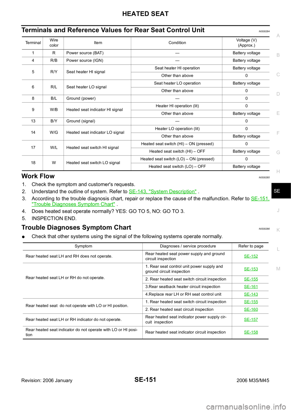
Terminals and Reference Values for Rear Seat Control UnitNIS00284
Work FlowNIS00285
1. Check the symptom and customer's requests.
2. Understand the outline of system. Refer to SE-143, "
System Description" .
3. According to the trouble diagnosis chart, repair or replace the cause of the malfunction. Refer to SE-151,
"Trouble Diagnoses Symptom Chart" .
4. Does heated seat operate normally? YES: GO TO 5, NO: GO TO 3.
5. INSPECTION END.
Trouble Diagnoses Symptom ChartNIS00286
Check that other systems using the signal of the following systems operate normally.
Te r m i n a lWire
colorItem ConditionVoltage (V)
(Approx.)
1 R Power source (BAT) — Battery voltage
4 R/B Power source (IGN) — Battery voltage
5 R/Y Seat heater HI signalSeat heater HI operation Battery voltage
Other than above 0
6 R/L Seat heater LO signalSeat heater LO operation Battery voltage
Other than above 0
8 B/L Ground (power) — 0
9 W/B Heated seat indicator HI signalHeater HI operation (lit) 0
Other than above Battery voltage
13 B/Y Ground (signal) — 0
14 W/G Heated seat indicator LO signalHeater LO operation (lit) 0
Other than above Battery voltage
17 W/L Heated seat switch HI signalHeated seat switch (HI) – ON (pressed) 0
Heated seat switch (HI) – OFF Battery voltage
18 W Heated seat switch LO signalHeated seat switch (LO) – ON (pressed) 0
Heated seat switch (LO) – OFF Battery voltage
Symptom Diagnoses / service procedure Refer to page
Rear heated seat LH and RH does not operate.Rear heated seat power supply and ground
circuit inspectionSE-152
Rear heated seat LH or RH do not operate.1. Rear seat control unit power supply and
ground circuit inspectionSE-1532. Rear heated seat switch circuit inspectionSE-155
3.Rear seatback heater circuit inspectionSE-161
4.Replace rear LH or RH seat control unitSE-143
Rear heated seat do not operate with LO or HI position.1. Rear heated seat switch circuit inspectionSE-1552. Rear heated seat circuit inspectionSE-160
Rear heated seat LH or RH indicator do not operate.Rear heated seat indicator power supply cir-
cuit inspectionSE-157
Rear heated seat indicator do not operate with LO or HI posi-
tionRear heated seat indicator circuit inspectionSE-158
Page 5531 of 5621

WT-6
ROAD WHEEL
Revision: 2006 January2006 M35/M45
ROAD WHEELPFP:40300
InspectionNES000JO
ALUMINUM WHEEL
1. Check tires for wear and improper inflation.
2. Check wheels for deformation, cracks and other damage. If deformed, remove wheel and check wheel
runout.
a. Remove tire from aluminum wheel and mount on a tire balance machine.
b. Set dial indicator as shown in the figure.
STEEL WHEEL
1. Check tires for wear and improper inflation.
2. Check wheels for deformation, cracks and other damage. If deformed, remove wheel and check wheel
runout.
a. Remove tire from steel wheel and mount on a tire balance machine.
b. Set two dial indicators as shown in the figure.
c. Set each dial indicator to 0.
d. Rotate wheel and check dial indicators at several points around
the circumference of the wheel.
e. Calculate runout at each point as shown below.
f. Select maximum positive runout value and the maximum nega-
tive value.
Add the two values to determine total runout.
In case a positive or negative value is not available, use the
maximum value (negative or positive) for total runout.
If the total runout value exceeds the limit, replace steel wheel. Wheel runout (Dial indicator value):
Refer to WT-41, "
SERVICE DATA
AND SPECIFICATIONS (SDS)" .
SFA975B
Radial runout = (A+B)/2
Lateral runout = (C+D)/2
Wheel runout : Refer to WT-41, "
SERVICE DATA AND
SPECIFICATIONS (SDS)" .
SEIA0558E