Page 4578 of 5621

ACTIVE AFS
LT-151
C
D
E
F
G
H
I
J
L
MA
B
LT
Revision: 2006 January2006 M35/M45
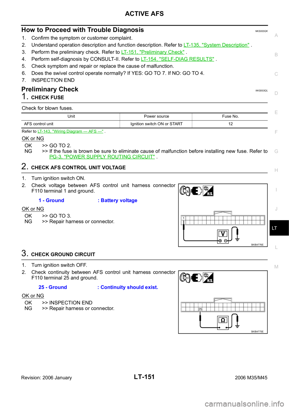
How to Proceed with Trouble DiagnosisNKS003QK
1. Confirm the symptom or customer complaint.
2. Understand operation description and function description. Refer to LT-135, "
System Description" .
3. Perform the preliminary check. Refer to LT- 1 5 1 , "
Preliminary Check" .
4. Perform self-diagnosis by CONSULT-II. Refer to LT-154, "
SELF-DIAG RESULTS" .
5. Check symptom and repair or replace the cause of malfunction.
6. Does the swivel control operate normally? If YES: GO TO 7. If NO: GO TO 4.
7. INSPECTION END
Preliminary CheckNKS003QL
1. CHECK FUSE
Check for blown fuses.
Refer to LT-143, "Wiring Diagram — AFS —" .
OK or NG
OK >> GO TO 2.
NG >> If the fuse is brown be sure to eliminate cause of malfunction before installing new fuse. Refer to
PG-3, "
POWER SUPPLY ROUTING CIRCUIT" .
2. CHECK AFS CONTROL UNIT VOLTAGE
1. Turn ignition switch ON.
2. Check voltage between AFS control unit harness connector
F110 terminal 1 and ground.
OK or NG
OK >> GO TO 3.
NG >> Repair harness or connector.
3. CHECK GROUND CIRCUIT
1. Turn ignition switch OFF.
2. Check continuity between AFS control unit harness connector
F110 terminal 25 and ground.
OK or NG
OK >> INSPECTION END
NG >> Repair harness or connector.
Unit Power source Fuse No.
AFS control unit Ignition switch ON or START 12
1 - Ground : Battery voltage
SKIB4776E
25 - Ground : Continuity should exist.
SKIB4775E
Page 4622 of 5621

FRONT FOG LAMP
LT-195
C
D
E
F
G
H
I
J
L
MA
B
LT
Revision: 2006 January2006 M35/M45
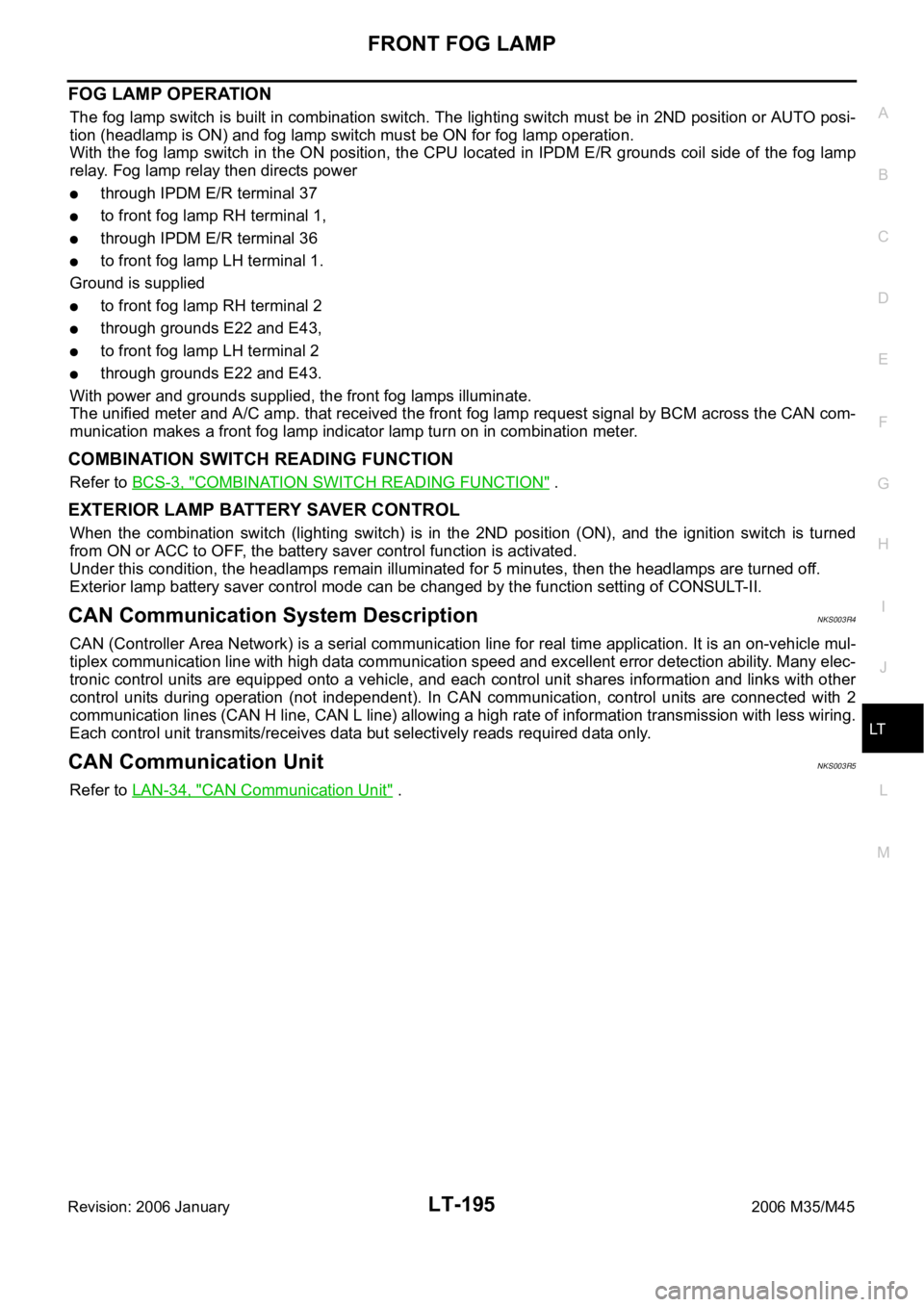
FOG LAMP OPERATION
The fog lamp switch is built in combination switch. The lighting switch must be in 2ND position or AUTO posi-
tion (headlamp is ON) and fog lamp switch must be ON for fog lamp operation.
With the fog lamp switch in the ON position, the CPU located in IPDM E/R grounds coil side of the fog lamp
relay. Fog lamp relay then directs power
through IPDM E/R terminal 37
to front fog lamp RH terminal 1,
through IPDM E/R terminal 36
to front fog lamp LH terminal 1.
Ground is supplied
to front fog lamp RH terminal 2
through grounds E22 and E43,
to front fog lamp LH terminal 2
through grounds E22 and E43.
With power and grounds supplied, the front fog lamps illuminate.
The unified meter and A/C amp. that received the front fog lamp request signal by BCM across the CAN com-
munication makes a front fog lamp indicator lamp turn on in combination meter.
COMBINATION SWITCH READING FUNCTION
Refer to BCS-3, "COMBINATION SWITCH READING FUNCTION" .
EXTERIOR LAMP BATTERY SAVER CONTROL
When the combination switch (lighting switch) is in the 2ND position (ON), and the ignition switch is turned
from ON or ACC to OFF, the battery saver control function is activated.
Under this condition, the headlamps remain illuminated for 5 minutes, then the headlamps are turned off.
Exterior lamp battery saver control mode can be changed by the function setting of CONSULT-II.
CAN Communication System DescriptionNKS003R4
CAN (Controller Area Network) is a serial communication line for real time application. It is an on-vehicle mul-
tiplex communication line with high data communication speed and excellent error detection ability. Many elec-
tronic control units are equipped onto a vehicle, and each control unit shares information and links with other
control units during operation (not independent). In CAN communication, control units are connected with 2
communication lines (CAN H line, CAN L line) allowing a high rate of information transmission with less wiring.
Each control unit transmits/receives data but selectively reads required data only.
CAN Communication UnitNKS003R5
Refer to LAN-34, "CAN Communication Unit" .
Page 4624 of 5621
FRONT FOG LAMP
LT-197
C
D
E
F
G
H
I
J
L
MA
B
LT
Revision: 2006 January2006 M35/M45
Wiring Diagram — F/FOG —NKS003R7
TKWT3387E
Page 4629 of 5621

LT-202
FRONT FOG LAMP
Revision: 2006 January2006 M35/M45
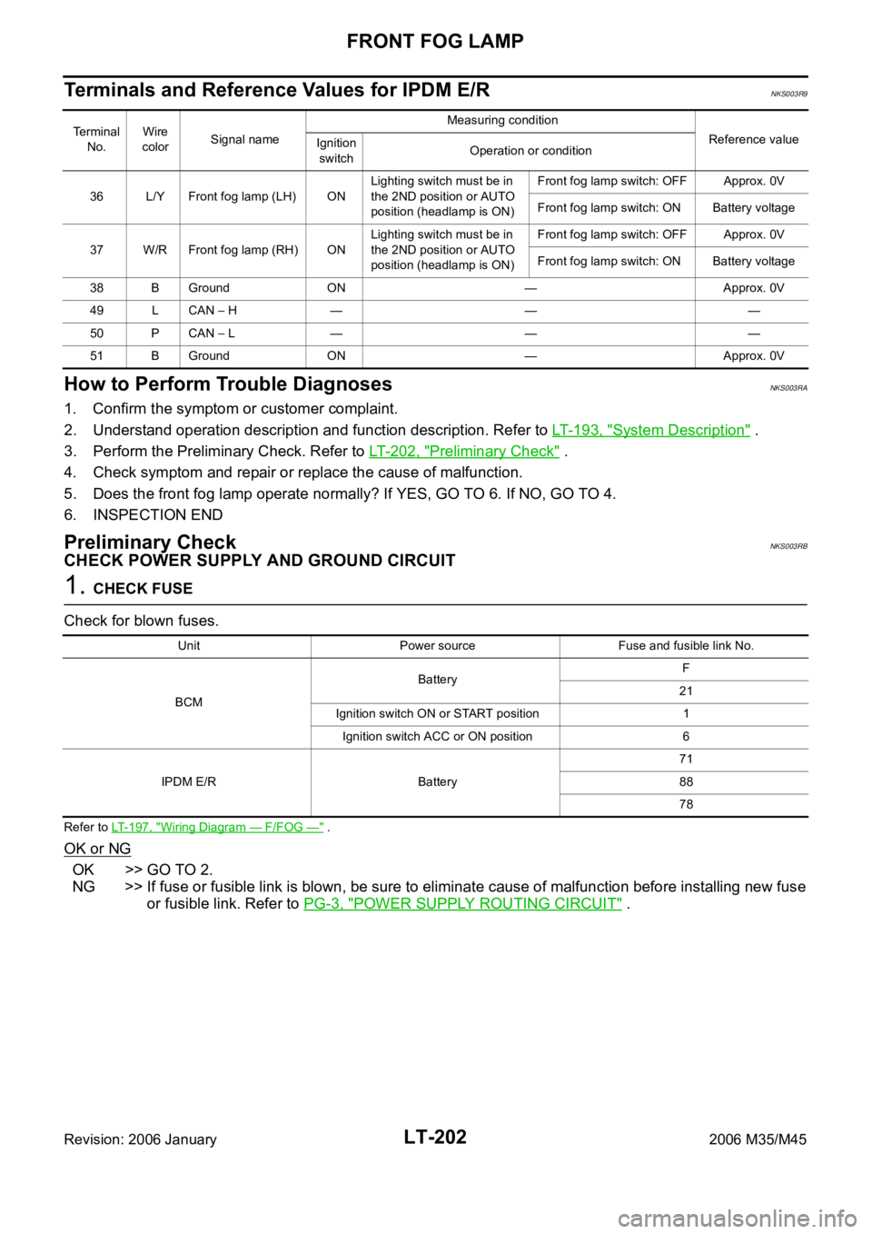
Terminals and Reference Values for IPDM E/RNKS003R9
How to Perform Trouble DiagnosesNKS003RA
1. Confirm the symptom or customer complaint.
2. Understand operation description and function description. Refer to LT- 1 9 3 , "
System Description" .
3. Perform the Preliminary Check. Refer to LT-202, "
Preliminary Check" .
4. Check symptom and repair or replace the cause of malfunction.
5. Does the front fog lamp operate normally? If YES, GO TO 6. If NO, GO TO 4.
6. INSPECTION END
Preliminary CheckNKS003RB
CHECK POWER SUPPLY AND GROUND CIRCUIT
1. CHECK FUSE
Check for blown fuses.
Refer to LT-197, "Wiring Diagram — F/FOG —" .
OK or NG
OK >> GO TO 2.
NG >> If fuse or fusible link is blown, be sure to eliminate cause of malfunction before installing new fuse
or fusible link. Refer to PG-3, "
POWER SUPPLY ROUTING CIRCUIT" .
Terminal
No.Wire
colorSignal nameMeasuring condition
Reference value
Ignition
switchOperation or condition
36 L/Y Front fog lamp (LH) ONLighting switch must be in
the 2ND position or AUTO
position (headlamp is ON)Front fog lamp switch: OFF Approx. 0V
Front fog lamp switch: ON Battery voltage
37 W/R Front fog lamp (RH) ONLighting switch must be in
the 2ND position or AUTO
position (headlamp is ON)Front fog lamp switch: OFF Approx. 0V
Front fog lamp switch: ON Battery voltage
38 B Ground ON — Approx. 0V
49 L CAN
H — — —
50 P CAN
L — — —
51 B Ground ON — Approx. 0V
Unit Power source Fuse and fusible link No.
BCMBatteryF
21
Ignition switch ON or START position 1
Ignition switch ACC or ON position 6
IPDM E/R Battery71
88
78
Page 4640 of 5621

TURN SIGNAL AND HAZARD WARNING LAMPS
LT-213
C
D
E
F
G
H
I
J
L
MA
B
LT
Revision: 2006 January2006 M35/M45
to BCM terminal 52
to combination meter terminals 9, 10 and 11
to unified meter and A/C amp. terminals 55 and 71
through grounds M16 and M70.
BCM then supplies power
through BCM terminal 45
to front combination lamp LH (turn signal) terminal 10
to side turn signal lamp LH terminal 1
to rear combination lamp LH (turn signal) terminal 3,
through BCM terminal 46
to front combination lamp RH (turn signal) terminal 10
to side turn signal lamp RH terminal 1
to rear combination lamp RH (turn signal) terminal 3.
Ground is supplied
to front combination lamp LH (turn signal) terminal 9
to front combination lamp RH (turn signal) terminal 9
to side turn signal lamp LH terminal 2
to side turn signal lamp RH terminal 2
through grounds E22 and E43,
to rear combination lamp LH (turn signal) terminal 4
to rear combination lamp RH (turn signal) terminal 4
through grounds B5, B40 and B131.
The BCM also supplies input to unified meter and A/C amp. terminals 56 and 72 across the CAN communica-
tion lines.
The unified meter and A/C amp. which received the turn indicator signal makes the left and right turn signal
indicator turn on in combination meter.
With power and input supplied, the BCM controls the flashing of the hazard warning lamps.
COMBINATION SWITCH READING FUNCTION
Refer to BCS-3, "COMBINATION SWITCH READING FUNCTION" .
CAN Communication System DescriptionNKS003RM
CAN (Controller Area Network) is a serial communication line for real time application. It is an on-vehicle mul-
tiplex communication line with high data communication speed and excellent error detection ability. Many elec-
tronic control units are equipped onto a vehicle, and each control unit shares information and links with other
control units during operation (not independent). In CAN communication, control units are connected with 2
communication lines (CAN H line, CAN L line) allowing a high rate of information transmission with less wiring.
Each control unit transmits/receives data but selectively reads required data only.
CAN Communication UnitNKS003RN
Refer to LAN-34, "CAN Communication Unit" .
Page 4642 of 5621
TURN SIGNAL AND HAZARD WARNING LAMPS
LT-215
C
D
E
F
G
H
I
J
L
MA
B
LT
Revision: 2006 January2006 M35/M45
Wiring Diagram — TURN —NKS003RP
TKWT3381E
Page 4648 of 5621

TURN SIGNAL AND HAZARD WARNING LAMPS
LT-221
C
D
E
F
G
H
I
J
L
MA
B
LT
Revision: 2006 January2006 M35/M45
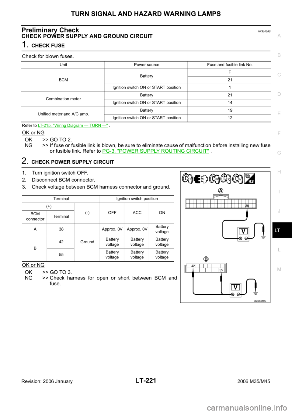
Preliminary CheckNKS003RS
CHECK POWER SUPPLY AND GROUND CIRCUIT
1. CHECK FUSE
Check for blown fuses.
Refer to LT-215, "Wiring Diagram — TURN —" .
OK or NG
OK >> GO TO 2.
NG >> If fuse or fusible link is blown, be sure to eliminate cause of malfunction before installing new fuse
or fusible link. Refer to PG-3, "
POWER SUPPLY ROUTING CIRCUIT" .
2. CHECK POWER SUPPLY CIRCUIT
1. Turn ignition switch OFF.
2. Disconnect BCM connector.
3. Check voltage between BCM harness connector and ground.
OK or NG
OK >> GO TO 3.
NG >> Check harness for open or short between BCM and
fuse.
Unit Power source Fuse and fusible link No.
BCMBatteryF
21
Ignition switch ON or START position 1
Combination meterBattery 21
Ignition switch ON or START position 14
Unified meter and A/C amp.Battery 19
Ignition switch ON or START position 12
Terminal Ignition switch position
(+)
(-) OFF ACC ON
BCM
connectorTerminal
A38
GroundApprox. 0V Approx. 0VBattery
voltage
B42Battery
voltageBattery
voltageBattery
voltage
55Battery
voltageBattery
voltageBattery
voltage
SKIB5059E
Page 4659 of 5621
LT-232
COMBINATION SWITCH
Revision: 2006 January2006 M35/M45
COMBINATION SWITCHPFP:25567
Wiring Diagram — COMBSW —NKS003S5
TKWT3385E