Page 3552 of 5621

POWER WINDOW SYSTEM
GW-33
C
D
E
F
G
H
J
K
L
MA
B
GW
Revision: 2006 January2006 M35/M45
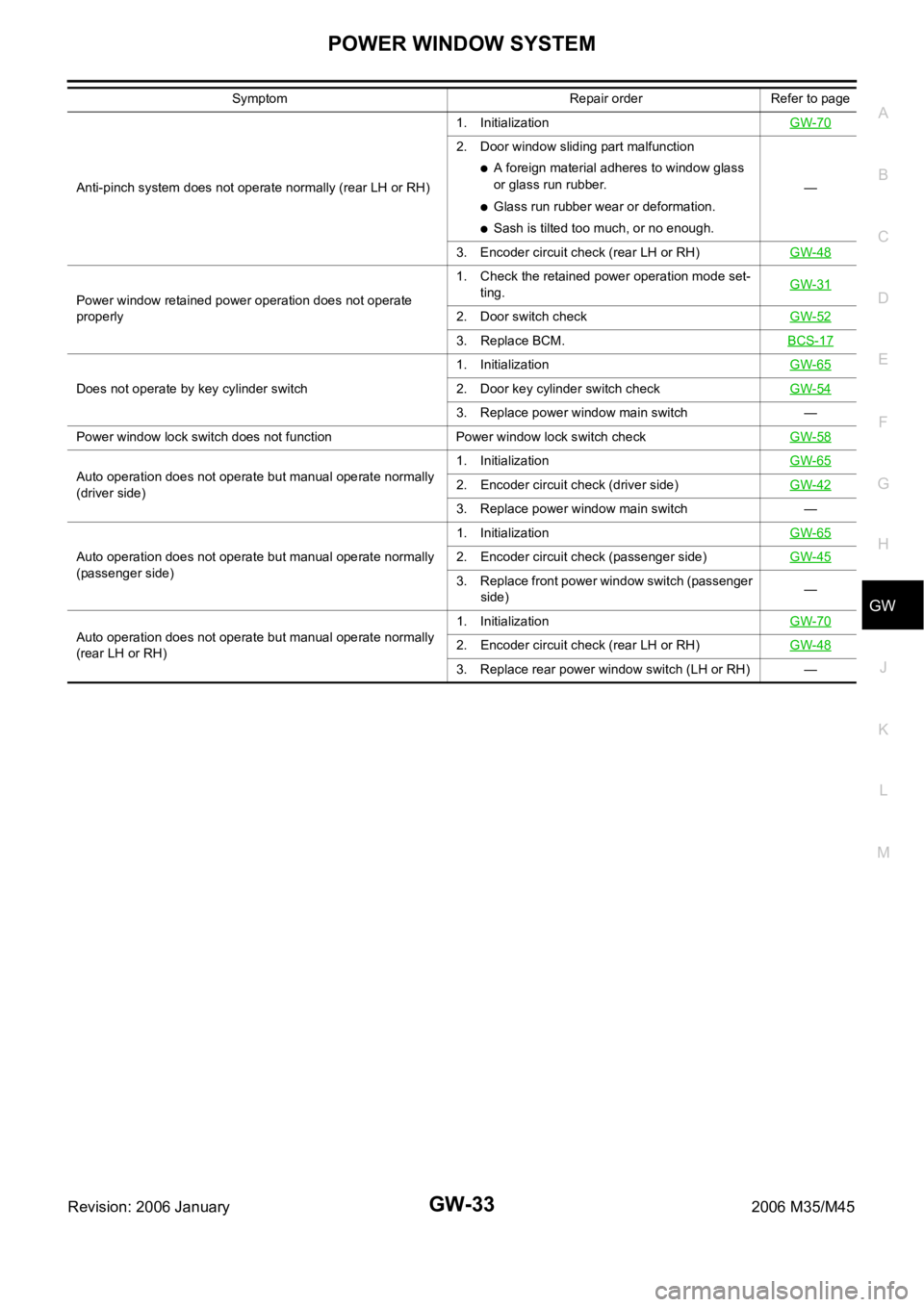
Anti-pinch system does not operate normally (rear LH or RH)1. InitializationGW-70
2. Door window sliding part malfunction
A foreign material adheres to window glass
or glass run rubber.
Glass run rubber wear or deformation.
Sash is tilted too much, or no enough.—
3. Encoder circuit check (rear LH or RH)GW-48
Power window retained power operation does not operate
properly1. Check the retained power operation mode set-
ting.GW-31
2. Door switch checkGW-52
3. Replace BCM.BCS-17
Does not operate by key cylinder switch1. InitializationGW-652. Door key cylinder switch checkGW-54
3. Replace power window main switch —
Power window lock switch does not function Power window lock switch checkGW-58
Auto operation does not operate but manual operate normally
(driver side)1. InitializationGW-652. Encoder circuit check (driver side)GW-42
3. Replace power window main switch —
Auto operation does not operate but manual operate normally
(passenger side)1. InitializationGW-65
2. Encoder circuit check (passenger side)GW-45
3. Replace front power window switch (passenger
side)—
Auto operation does not operate but manual operate normally
(rear LH or RH)1. InitializationGW-70
2. Encoder circuit check (rear LH or RH)GW-48
3. Replace rear power window switch (LH or RH) — Symptom Repair order Refer to page
Page 3553 of 5621
![INFINITI M35 2006 Factory Service Manual GW-34
POWER WINDOW SYSTEM
Revision: 2006 January2006 M35/M45
BCM Power Supply and Ground Circuit CheckNIS0021R
1. CHECK FUSE
Check 15A fuse [No. 1, located in fuse block (J/B)]
Check 10A fuse [No. 21, INFINITI M35 2006 Factory Service Manual GW-34
POWER WINDOW SYSTEM
Revision: 2006 January2006 M35/M45
BCM Power Supply and Ground Circuit CheckNIS0021R
1. CHECK FUSE
Check 15A fuse [No. 1, located in fuse block (J/B)]
Check 10A fuse [No. 21,](/manual-img/42/57023/w960_57023-3552.png)
GW-34
POWER WINDOW SYSTEM
Revision: 2006 January2006 M35/M45
BCM Power Supply and Ground Circuit CheckNIS0021R
1. CHECK FUSE
Check 15A fuse [No. 1, located in fuse block (J/B)]
Check 10A fuse [No. 21, located in fuse block (J/B)]
Check 50A fusible link (letter F , located in the fuse and fusible link box).
NOTE:
Refer to GW-13, "
Component Parts and Harness Connector Location" .
OK or NG
OK >> GO TO 2.
NG >> If fuse is blown out, be sure to eliminate cause of malfunction before installing new fuse. Refer to
PG-3, "
POWER SUPPLY ROUTING CIRCUIT" .
2. CHECK POWER SUPPLY CIRCUIT
Check voltage between BCM connector and ground.
OK or NG
OK >> GO TO 3.
NG >> Check BCM power supply circuit for open or short.
3. CHECK GROUND CIRCUIT
1. Turn ignition switch OFF.
2. Disconnect BCM connector.
3. Check continuity between BCM connector and ground.
OK or NG
OK >> Power supply and ground circuit are OK.
NG >> Check BCM ground circuit for open or short.
Te r m i n a l s
Condition of
ignition switchVoltage (V)
(Approx.) (+)
(–)
BCM connector Terminal
M1 38
GroundON
Battery voltage
M242
OFF
55
PIIB5934E
BCM connector Terminal
GroundContinuity
M2 52 Yes
PIIB5935E
Page 3573 of 5621

GW-54
POWER WINDOW SYSTEM
Revision: 2006 January2006 M35/M45
Front Door Key Cylinder Switch Check NIS00222
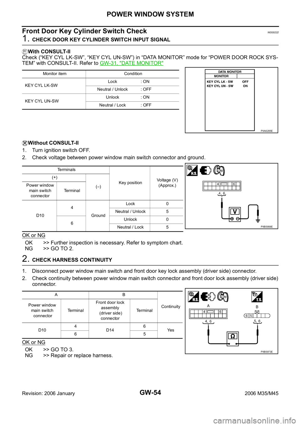
1. CHECK DOOR KEY CYLINDER SWITCH INPUT SIGNAL
With CONSULT-II
Check (“KEY CYL LK-SW”, “KEY CYL UN-SW”) in “DATA MONITOR” mode for “POWER DOOR ROCK SYS-
TEM” with CONSULT-II. Refer to GW-31, "
DATE MONITOR"
Without CONSULT-II
1. Turn ignition switch OFF.
2. Check voltage between power window main switch connector and ground.
OK or NG
OK >> Further inspection is necessary. Refer to symptom chart.
NG >> GO TO 2.
2. CHECK HARNESS CONTINUITY
1. Disconnect power window main switch and front door key lock assembly (driver side) connector.
2. Check continuity between power window main switch connector and front door lock assembly (driver side)
connector.
OK or NG
OK >> GO TO 3.
NG >> Repair or replace harness.
Monitor item Condition
KEY CYL LK-SWLock : ON
Neutral / Unlock : OFF
KEY CYL UN-SWUnlock : ON
Neutral / Lock : OFF
PIIA6285E
Te r m i n a l s
Key positionVoltage (V)
(Approx.) (+)
(–) Power window
main switch
connectorTerminal
D104
GroundLock 0
Neutral / Unlock 5
6Unlock 0
Neutral / Lock 5
PIIB5956E
AB
Continuity Power window
main switch
connectorTe r m i n a lFront door lock
assembly
(driver side)
connectorTerminal
D104
D146
Ye s
65
PIIB5973E
Page 3574 of 5621
POWER WINDOW SYSTEM
GW-55
C
D
E
F
G
H
J
K
L
MA
B
GW
Revision: 2006 January2006 M35/M45
3. CHECK DOOR KEY CYLINDER SWITCH GROUND
Check continuity between front door lock assembly (driver side) connector ground.
OK or NG
OK >> GO TO 4.
NG >> Repair or replace harness.
4. CHECK DOOR KEY CYLINDER SWITCH
Check front door lock assembly (driver side).
OK or NG
OK >> Further inspection is necessary. Refer to symptom
chart.
NG >> Replace front door key cylinder (driver side) switch.
Front door lock
assembly
(driver side)
connectorTerminal
GroundContinuity
D14 4 Yes
PIIB5974E
Te r m i n a l
Key position Continuity
Front door lock assembly
(driver side)
5
4Unlock Yes
Neutral / Lock No
6Lock Yes
Neutral / Unlock No
PIIB5975E
Page 3575 of 5621

GW-56
POWER WINDOW SYSTEM
Revision: 2006 January2006 M35/M45
Power Window Serial Link Check (Passenger Side)NIS00223
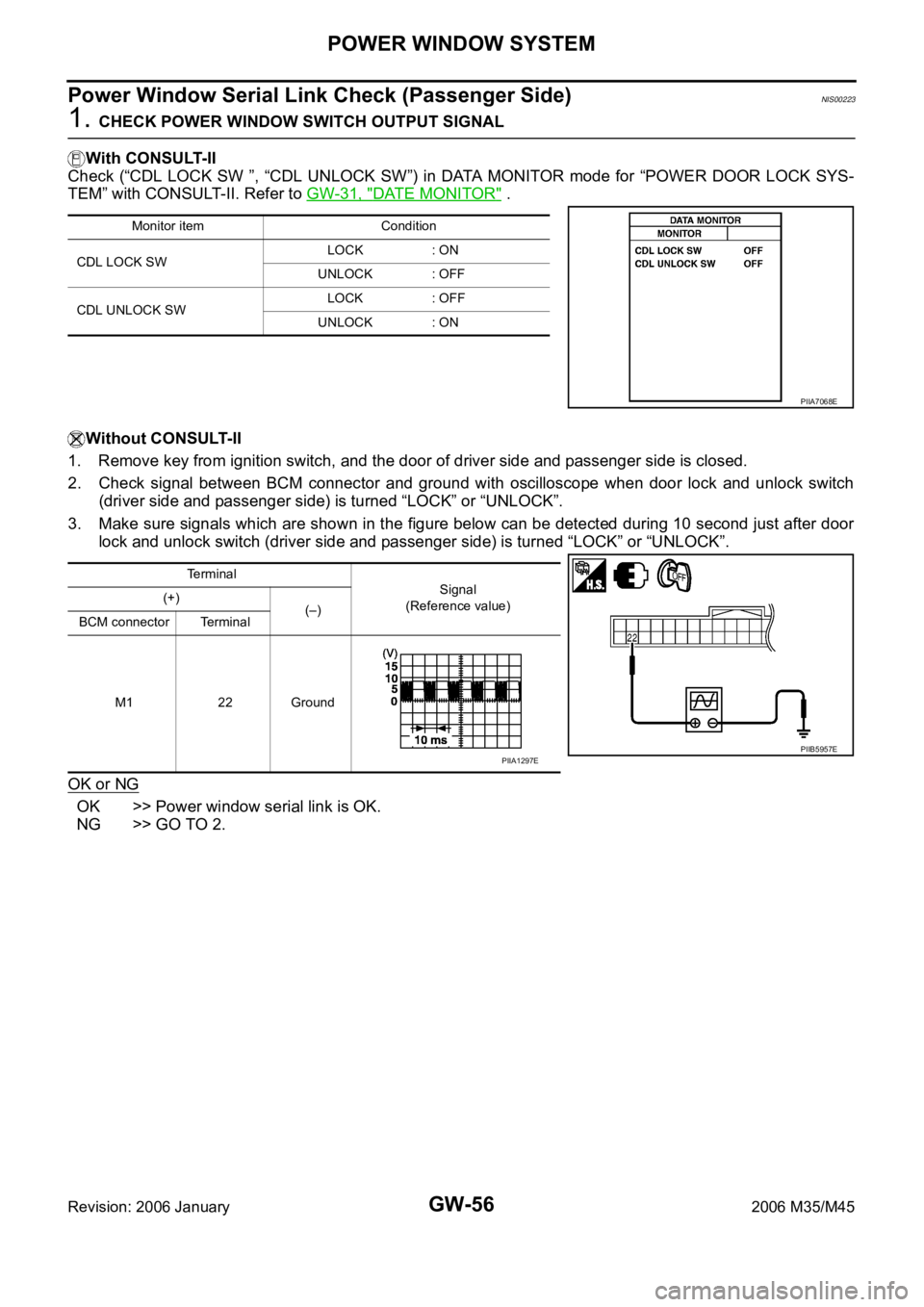
1. CHECK POWER WINDOW SWITCH OUTPUT SIGNAL
With CONSULT-II
Check (“CDL LOCK SW ”, “CDL UNLOCK SW”) in DATA MONITOR mode for “POWER DOOR LOCK SYS-
TEM” with CONSULT-II. Refer to GW-31, "
DATE MONITOR" .
Without CONSULT-II
1. Remove key from ignition switch, and the door of driver side and passenger side is closed.
2. Check signal between BCM connector and ground with oscilloscope when door lock and unlock switch
(driver side and passenger side) is turned “LOCK” or “UNLOCK”.
3. Make sure signals which are shown in the figure below can be detected during 10 second just after door
lock and unlock switch (driver side and passenger side) is turned “LOCK” or “UNLOCK”.
OK or NG
OK >> Power window serial link is OK.
NG >> GO TO 2.
Monitor item Condition
CDL LOCK SW LOCK : ON
UNLOCK : OFF
CDL UNLOCK SW LOCK : OFF
UNLOCK : ON
PIIA7068E
Terminal
Signal
(Reference value) (+)
(–)
BCM connector Terminal
M1 22 Ground
PIIB5957EPIIA1297E
Page 3577 of 5621

GW-58
POWER WINDOW SYSTEM
Revision: 2006 January2006 M35/M45
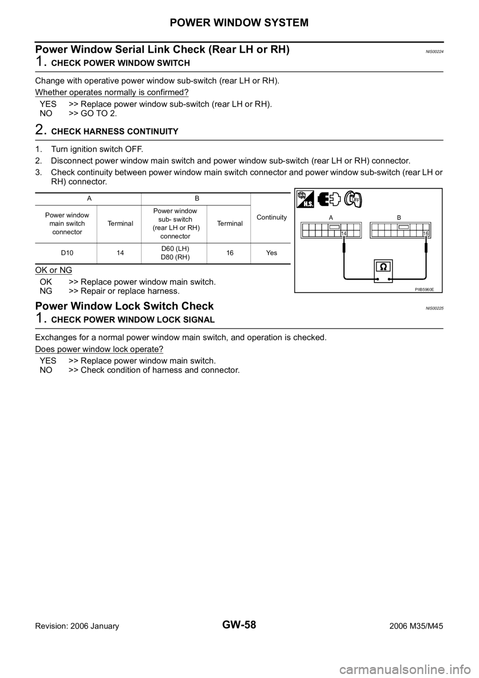
Power Window Serial Link Check (Rear LH or RH)NIS00224
1. CHECK POWER WINDOW SWITCH
Change with operative power window sub-switch (rear LH or RH).
Whether operates normally is confirmed?
YES >> Replace power window sub-switch (rear LH or RH).
NO >> GO TO 2.
2. CHECK HARNESS CONTINUITY
1. Turn ignition switch OFF.
2. Disconnect power window main switch and power window sub-switch (rear LH or RH) connector.
3. Check continuity between power window main switch connector and power window sub-switch (rear LH or
RH) connector.
OK or NG
OK >> Replace power window main switch.
NG >> Repair or replace harness.
Power Window Lock Switch CheckNIS00225
1. CHECK POWER WINDOW LOCK SIGNAL
Exchanges for a normal power window main switch, and operation is checked.
Does power window lock operate?
YES >> Replace power window main switch.
NO >> Check condition of harness and connector.
AB
Continuity Power window
main switch
connectorTe r m i n a lPower window
sub- switch
(rear LH or RH)
connectorTerminal
D10 14D60 (LH)
D80 (RH)16 Yes
PIIB5960E
Page 3592 of 5621
REAR WINDOW DEFOGGER
GW-73
C
D
E
F
G
H
J
K
L
MA
B
GW
Revision: 2006 January2006 M35/M45
REAR WINDOW DEFOGGERPFP:25350
Component Parts and Harness Connector LocationNIS0022G
System DescriptionNIS0022H
The rear window defogger system is controlled by BCM and IPDM E/R.
The rear window defogger operates only for approximately 15 minutes.
Power is at all times supplied
through 20A fuse [No. 75, located in the IPDM E/R]
to rear window defogger relay terminals 6,
through 20A fuse [No. 80, located in the IPDM E/R]
to rear window defogger relay terminals 3,
through 15A fuse [No. 37, located in the fuse and fusible link box
to multi-function switch terminal 1,
PIIB6098E
1. Fuse block (J/B) 2. Fuse and fusible link box 3. Fuse block (in IPDM E/R)
4. IPDM E/R E4, E8, E9 5. BCM M1, M2 6.Rear window defogger switch (in
multi function switch) M69
7. Rear window defogger relay E36 8.a : Rear window defogger B604
b : Condenser B49
Page 3593 of 5621

GW-74
REAR WINDOW DEFOGGER
Revision: 2006 January2006 M35/M45
through 50A fusible link (letter F , located in the fuse and fusible link box)
to BCM terminal 55,
through 10A fuse [No. 21, located in the fuse block (J/B)]
to BCM terminal 42.
With the ignition switch turned to ON or START position,
Power is supplied
through 15A fuse [No. 1, located in the fuse block (J/B)]
to BCM terminal 38.
through 10A fuse [No. 12, located in the fuse block (J/B)]
to rear window defogger relay terminal 1.
With the ignition switch turned to ACC or ON position,
through 10A fuse [No. 6, located in the fuse block (J/B)]
to multi-function switch terminal 2.
Ground is supplied
to BCM terminal 52
through body grounds M16 and M70,
to multi-function switch terminal 14
through body grounds M16 and M70,
to IPDM E/R terminals 38 and 51
through body grounds E22 and E43.
When rear window defogger switch in multi-function switch is turned to ON.
Then multi-function switch recognizes that rear window defogger switch is turned to ON.
Then it sends rear window defogger switch signals to AV control unit (without navigation system) or NAVI con-
trol unit (with navigation system) via AV line.
When AV control unit (without navigation system) or NAVI control unit (with navigation system) receives rear
window defogger switch signals, and display on the screen.
Then AV control unit (without navigation system) or NAVI control unit (with navigation system) recognizes that
rear window defogger switch is turned to ON.
Then it sends rear window defogger switch signal to BCM via DATA LINE (CAN H, CAN L).
Then BCM recognizes that rear window defogger switch signal.
Then it sends rear window defogger request signal to IPDM E/R via DATA LINE (CAN H, CAN L).
When IPDM E/R receives rear window defogger switch signals,
Ground is supplied
to rear window defogger relay terminal 2
through IPDM E/R terminal 57
through IPDM E/R terminal 51
through body grounds E22 and E43.
And then rear window defogger relay is energized.
When rear window defogger relay is turned ON, signals are transmitted.
through rear window defogger relay terminals 5 and 7
through condenser terminal 1
to rear window defogger terminal 1
Rear window defogger terminal 2 is grounded through grounds B702.
With power and ground supplied, rear window defogger filaments heat and defog the rear window.
When rear window defogger relay is turned to ON,
Power is supplied
through rear window defogger relay terminals 5 and 7
through fuse block (J/B) terminal 2C
through 10A fuse [No. 8, located in the fuse block (J/B)] and
through fuse block (J/B) terminal 5B
to door mirror (LH and RH) terminal 4.
Door mirror (LH and RH) terminal 8 is grounded through body grounds M16 and M70.