2006 INFINITI M35 lock
[x] Cancel search: lockPage 3604 of 5621
REAR WINDOW DEFOGGER
GW-85
C
D
E
F
G
H
J
K
L
MA
B
GW
Revision: 2006 January2006 M35/M45
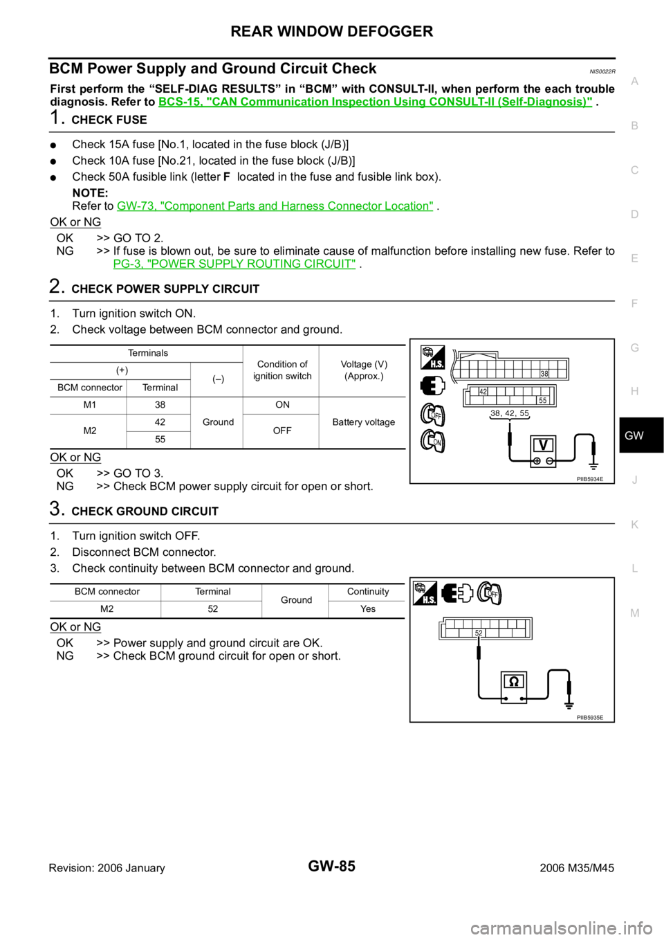
BCM Power Supply and Ground Circuit CheckNIS0022R
First perform the “SELF-DIAG RESULTS” in “BCM” with CONSULT-II, when perform the each trouble
diagnosis. Refer to BCS-15, "
CAN Communication Inspection Using CONSULT-II (Self-Diagnosis)" .
1. CHECK FUSE
Check 15A fuse [No.1, located in the fuse block (J/B)]
Check 10A fuse [No.21, located in the fuse block (J/B)]
Check 50A fusible link (letter F located in the fuse and fusible link box).
NOTE:
Refer to GW-73, "
Component Parts and Harness Connector Location" .
OK or NG
OK >> GO TO 2.
NG >> If fuse is blown out, be sure to eliminate cause of malfunction before installing new fuse. Refer to
PG-3, "
POWER SUPPLY ROUTING CIRCUIT" .
2. CHECK POWER SUPPLY CIRCUIT
1. Turn ignition switch ON.
2. Check voltage between BCM connector and ground.
OK or NG
OK >> GO TO 3.
NG >> Check BCM power supply circuit for open or short.
3. CHECK GROUND CIRCUIT
1. Turn ignition switch OFF.
2. Disconnect BCM connector.
3. Check continuity between BCM connector and ground.
OK or NG
OK >> Power supply and ground circuit are OK.
NG >> Check BCM ground circuit for open or short.
Terminals
Condition of
ignition switchVoltage (V)
(Approx.) (+)
(–)
BCM connector Terminal
M1 38
GroundON
Battery voltage
M242
OFF
55
PIIB5934E
BCM connector Terminal
GroundContinuity
M2 52 Yes
PIIB5935E
Page 3605 of 5621
GW-86
REAR WINDOW DEFOGGER
Revision: 2006 January2006 M35/M45
Rear Window Defogger Switch Circuit CheckNIS0022S
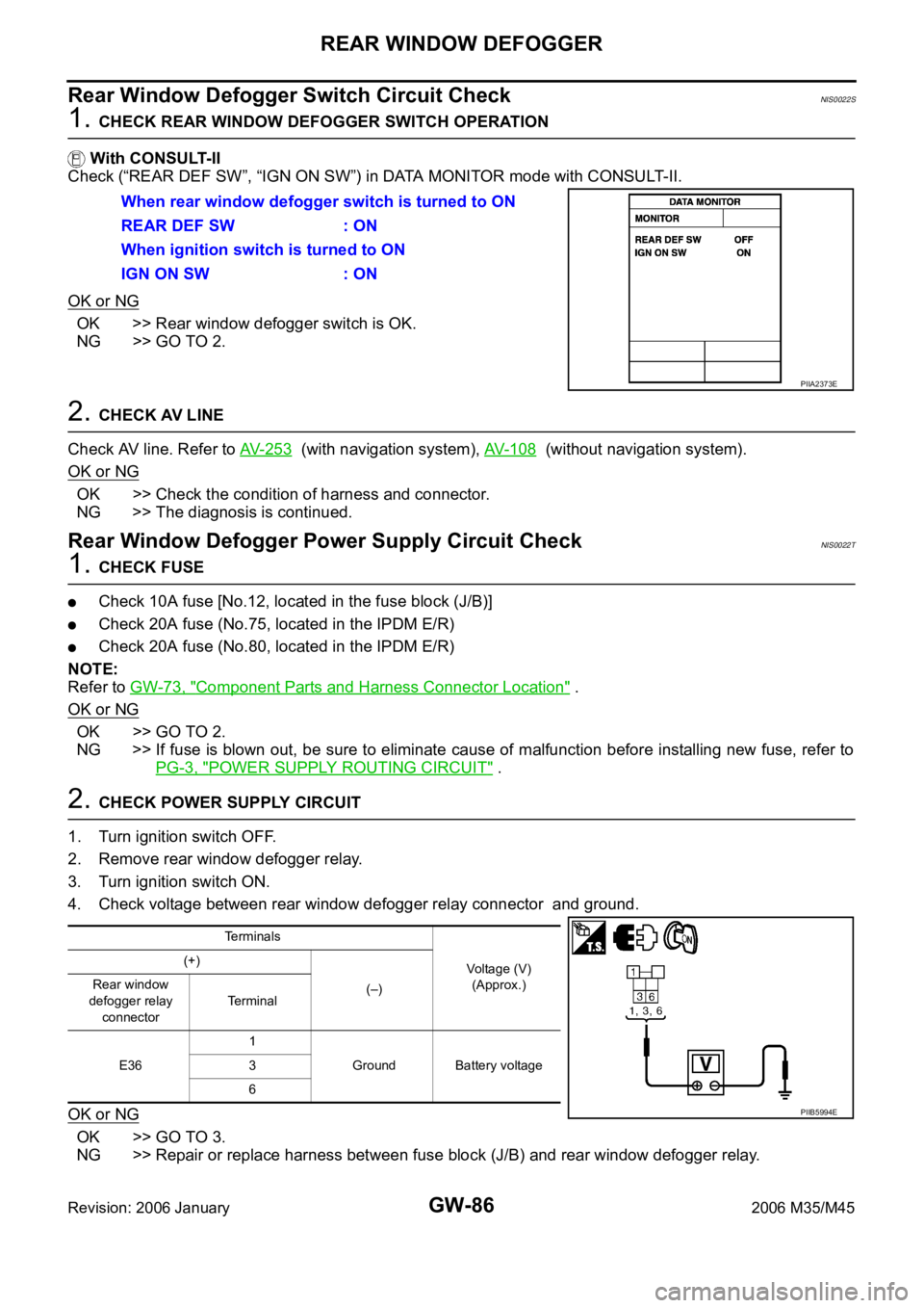
1. CHECK REAR WINDOW DEFOGGER SWITCH OPERATION
With CONSULT-II
Check (“REAR DEF SW”, “IGN ON SW”) in DATA MONITOR mode with CONSULT-II.
OK or NG
OK >> Rear window defogger switch is OK.
NG >> GO TO 2.
2. CHECK AV LINE
Check AV line. Refer to AV- 2 5 3
(with navigation system), AV- 1 0 8 (without navigation system).
OK or NG
OK >> Check the condition of harness and connector.
NG >> The diagnosis is continued.
Rear Window Defogger Power Supply Circuit CheckNIS0022T
1. CHECK FUSE
Check 10A fuse [No.12, located in the fuse block (J/B)]
Check 20A fuse (No.75, located in the IPDM E/R)
Check 20A fuse (No.80, located in the IPDM E/R)
NOTE:
Refer to GW-73, "
Component Parts and Harness Connector Location" .
OK or NG
OK >> GO TO 2.
NG >> If fuse is blown out, be sure to eliminate cause of malfunction before installing new fuse, refer to
PG-3, "
POWER SUPPLY ROUTING CIRCUIT" .
2. CHECK POWER SUPPLY CIRCUIT
1. Turn ignition switch OFF.
2. Remove rear window defogger relay.
3. Turn ignition switch ON.
4. Check voltage between rear window defogger relay connector and ground.
OK or NG
OK >> GO TO 3.
NG >> Repair or replace harness between fuse block (J/B) and rear window defogger relay. When rear window defogger switch is turned to ON
REAR DEF SW : ON
When ignition switch is turned to ON
IGN ON SW : ON
PIIA2373E
Terminals
Voltage (V)
(Approx.) (+)
(–) Rear window
defogger relay
connectorTerminal
E361
Ground Battery voltage 3
6
PIIB5994E
Page 3608 of 5621
REAR WINDOW DEFOGGER
GW-89
C
D
E
F
G
H
J
K
L
MA
B
GW
Revision: 2006 January2006 M35/M45
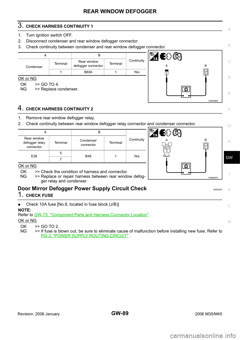
3. CHECK HARNESS CONTINUITY 1
1. Turn ignition switch OFF.
2. Disconnect condenser and rear window defogger connector.
3. Check continuity between condenser and rear window defogger connector.
OK or NG
OK >> GO TO 4.
NG >> Replace condenser.
4. CHECK HARNESS CONTINUITY 2
1. Remove rear window defogger relay.
2. Check continuity between rear window defogger relay connector and condenser connector.
OK or NG
OK >> Check the condition of harness and connector.
NG >> Replace or repair harness between rear window defog-
ger relay and condenser.
Door Mirror Defogger Power Supply Circuit CheckNIS0022V
1. CHECK FUSE
Check 10A fuse [No.8, located in fuse block (J/B)]
NOTE:
Refer to GW-73, "
Component Parts and Harness Connector Location" .
OK or NG
OK >> GO TO 2.
NG >> If fuse is blown out, be sure to eliminate cause of malfunction before installing new fuse. Refer to
PG-3, "
POWER SUPPLY ROUTING CIRCUIT" .
AB
Continuity
CondenserTerminalRear window
defogger connectorTerminal
1B6041Yes
PIIB5986E
AB
Continuity Rear window
defogger relay
connectorTerminalCondenser
connectorTerminal
E365
B49 1 Yes
7
PIIB5987E
Page 3609 of 5621
GW-90
REAR WINDOW DEFOGGER
Revision: 2006 January2006 M35/M45
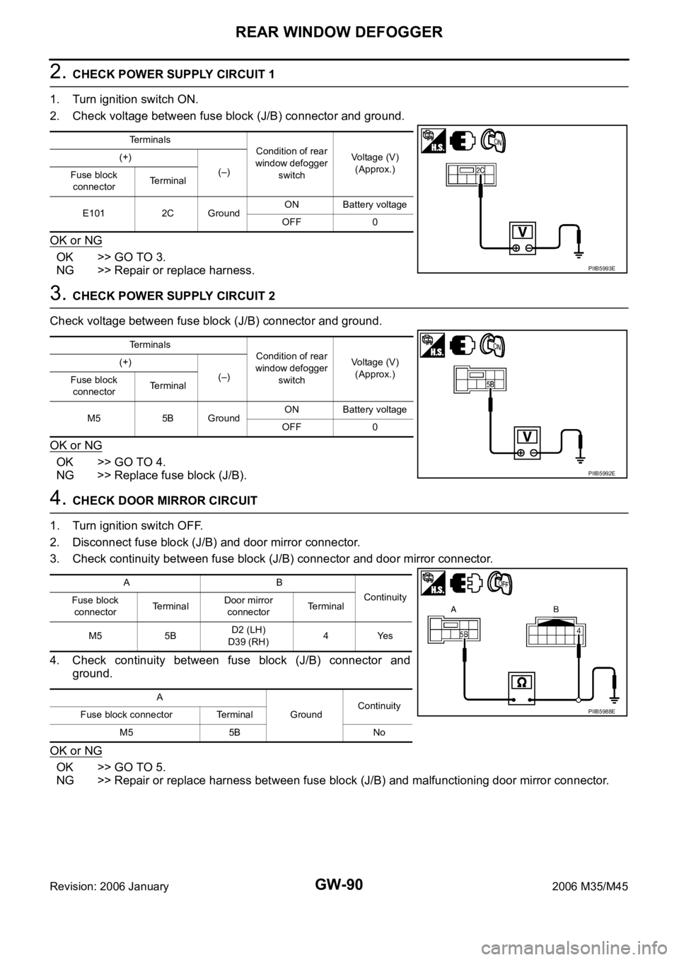
2. CHECK POWER SUPPLY CIRCUIT 1
1. Turn ignition switch ON.
2. Check voltage between fuse block (J/B) connector and ground.
OK or NG
OK >> GO TO 3.
NG >> Repair or replace harness.
3. CHECK POWER SUPPLY CIRCUIT 2
Check voltage between fuse block (J/B) connector and ground.
OK or NG
OK >> GO TO 4.
NG >> Replace fuse block (J/B).
4. CHECK DOOR MIRROR CIRCUIT
1. Turn ignition switch OFF.
2. Disconnect fuse block (J/B) and door mirror connector.
3. Check continuity between fuse block (J/B) connector and door mirror connector.
4. Check continuity between fuse block (J/B) connector and
ground.
OK or NG
OK >> GO TO 5.
NG >> Repair or replace harness between fuse block (J/B) and malfunctioning door mirror connector.
Terminals
Condition of rear
window defogger
switchVoltage (V)
(Approx.) (+)
(–)
Fuse block
connectorTerminal
E101 2C GroundON Battery voltage
OFF 0
PIIB5993E
Terminals
Condition of rear
window defogger
switchVoltage (V)
(Approx.) (+)
(–)
Fuse block
connectorTerminal
M5 5B GroundON Battery voltage
OFF 0
PIIB5992E
AB
Continuity
Fuse block
connectorTe r m i n a lDoor mirror
connectorTerminal
M5 5BD2 (LH)
D39 (RH)4Yes
A
GroundContinuity
Fuse block connector Terminal
M5 5B No
PIIB5988E
Page 3610 of 5621
REAR WINDOW DEFOGGER
GW-91
C
D
E
F
G
H
J
K
L
MA
B
GW
Revision: 2006 January2006 M35/M45
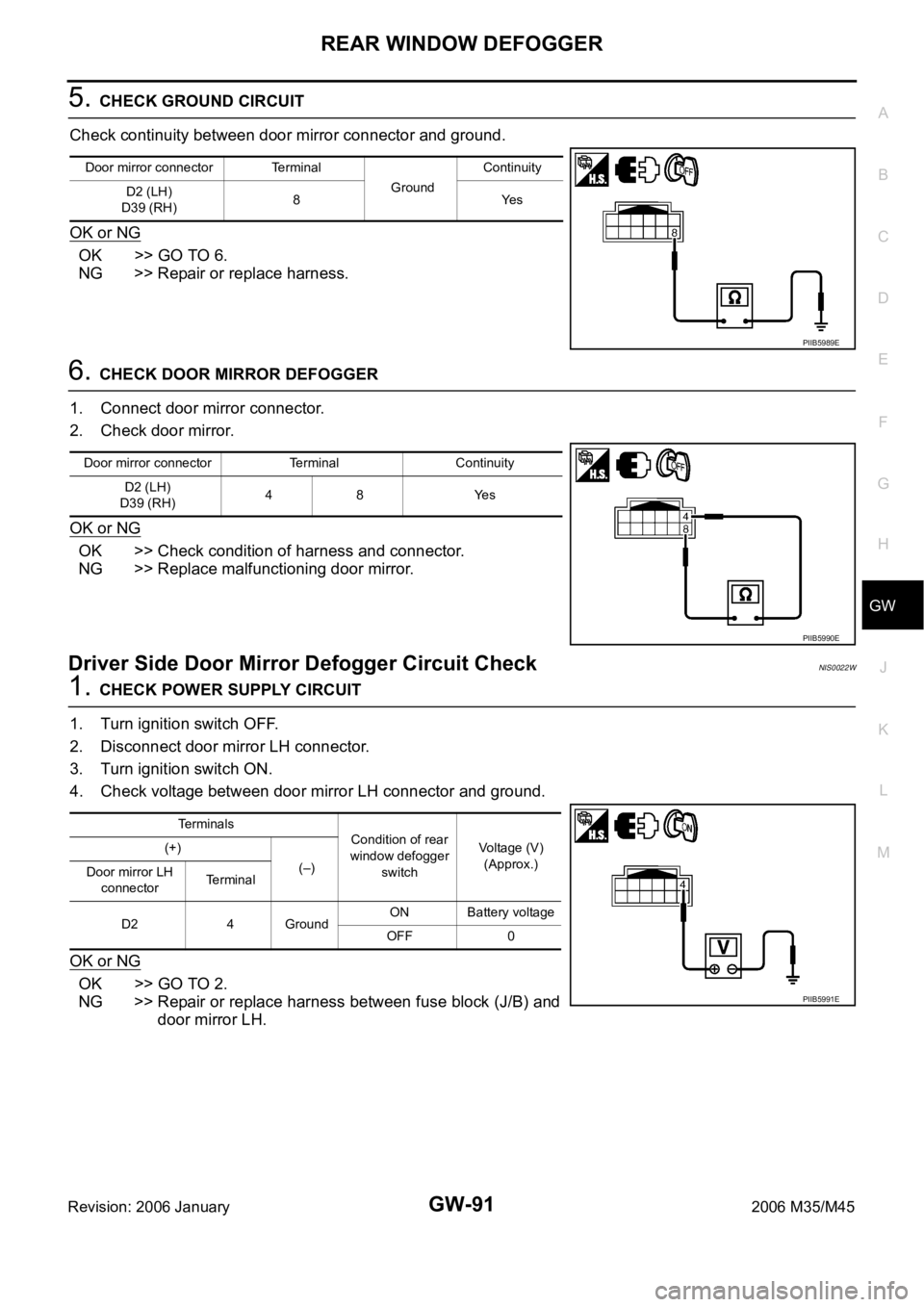
5. CHECK GROUND CIRCUIT
Check continuity between door mirror connector and ground.
OK or NG
OK >> GO TO 6.
NG >> Repair or replace harness.
6. CHECK DOOR MIRROR DEFOGGER
1. Connect door mirror connector.
2. Check door mirror.
OK or NG
OK >> Check condition of harness and connector.
NG >> Replace malfunctioning door mirror.
Driver Side Door Mirror Defogger Circuit CheckNIS0022W
1. CHECK POWER SUPPLY CIRCUIT
1. Turn ignition switch OFF.
2. Disconnect door mirror LH connector.
3. Turn ignition switch ON.
4. Check voltage between door mirror LH connector and ground.
OK or NG
OK >> GO TO 2.
NG >> Repair or replace harness between fuse block (J/B) and
door mirror LH.
Door mirror connector Terminal
GroundContinuity
D2 (LH)
D39 (RH)8Yes
PIIB5989E
Door mirror connector Terminal Continuity
D2 (LH)
D39 (RH)48 Yes
PIIB5990E
Te r m i n a l s
Condition of rear
window defogger
switchVoltage (V)
(Approx.) (+)
(–)
Door mirror LH
connectorTe r m i n a l
D2 4 GroundON Battery voltage
OFF 0
PIIB5991E
Page 3611 of 5621
GW-92
REAR WINDOW DEFOGGER
Revision: 2006 January2006 M35/M45
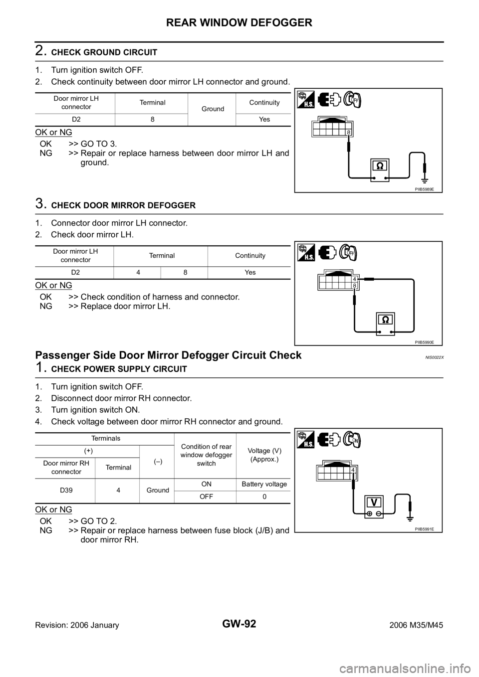
2. CHECK GROUND CIRCUIT
1. Turn ignition switch OFF.
2. Check continuity between door mirror LH connector and ground.
OK or NG
OK >> GO TO 3.
NG >> Repair or replace harness between door mirror LH and
ground.
3. CHECK DOOR MIRROR DEFOGGER
1. Connector door mirror LH connector.
2. Check door mirror LH.
OK or NG
OK >> Check condition of harness and connector.
NG >> Replace door mirror LH.
Passenger Side Door Mirror Defogger Circuit Check NIS0022X
1. CHECK POWER SUPPLY CIRCUIT
1. Turn ignition switch OFF.
2. Disconnect door mirror RH connector.
3. Turn ignition switch ON.
4. Check voltage between door mirror RH connector and ground.
OK or NG
OK >> GO TO 2.
NG >> Repair or replace harness between fuse block (J/B) and
door mirror RH.
Door mirror LH
connectorTerminal
GroundContinuity
D2 8 Yes
PIIB5989E
Door mirror LH
connectorTerminal Continuity
D2 4 8 Yes
PIIB5990E
Terminals
Condition of rear
window defogger
switchVoltage (V)
(Approx.) (+)
(–)
Door mirror RH
connectorTerminal
D39 4 GroundON Battery voltage
OFF 0
PIIB5991E
Page 3615 of 5621
GW-96
REVERSE INTERLOCK DOOR MIRROR SYSTEM
Revision: 2006 January2006 M35/M45
REVERSE INTERLOCK DOOR MIRROR SYSTEMPFP:28548
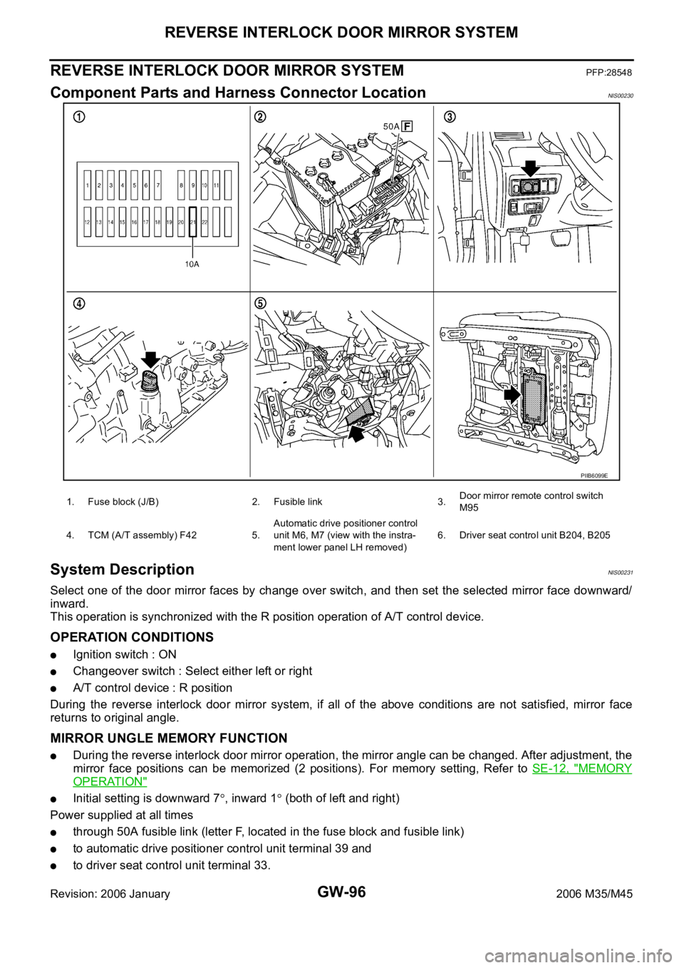
Component Parts and Harness Connector LocationNIS00230
System DescriptionNIS00231
Select one of the door mirror faces by change over switch, and then set the selected mirror face downward/
inward.
This operation is synchronized with the R position operation of A/T control device.
OPERATION CONDITIONS
Ignition switch : ON
Changeover switch : Select either left or right
A/T control device : R position
During the reverse interlock door mirror system, if all of the above conditions are not satisfied, mirror face
returns to original angle.
MIRROR UNGLE MEMORY FUNCTION
During the reverse interlock door mirror operation, the mirror angle can be changed. After adjustment, the
mirror face positions can be memorized (2 positions). For memory setting, Refer to SE-12, "
MEMORY
OPERATION"
Initial setting is downward 7, inward 1 (both of left and right)
Power supplied at all times
through 50A fusible link (letter F, located in the fuse block and fusible link)
to automatic drive positioner control unit terminal 39 and
to driver seat control unit terminal 33.
PIIB6099E
1. Fuse block (J/B) 2. Fusible link 3.Door mirror remote control switch
M95
4. TCM (A/T assembly) F42 5.Automatic drive positioner control
unit M6, M7 (view with the instra-
ment lower panel LH removed)6. Driver seat control unit B204, B205
Page 3616 of 5621
![INFINITI M35 2006 Factory Service Manual REVERSE INTERLOCK DOOR MIRROR SYSTEM
GW-97
C
D
E
F
G
H
J
K
L
MA
B
GW
Revision: 2006 January2006 M35/M45
through 10A fuse [No.21, located in the fuse block (J/B)]
to automatic drive positioner control INFINITI M35 2006 Factory Service Manual REVERSE INTERLOCK DOOR MIRROR SYSTEM
GW-97
C
D
E
F
G
H
J
K
L
MA
B
GW
Revision: 2006 January2006 M35/M45
through 10A fuse [No.21, located in the fuse block (J/B)]
to automatic drive positioner control](/manual-img/42/57023/w960_57023-3615.png)
REVERSE INTERLOCK DOOR MIRROR SYSTEM
GW-97
C
D
E
F
G
H
J
K
L
MA
B
GW
Revision: 2006 January2006 M35/M45
through 10A fuse [No.21, located in the fuse block (J/B)]
to automatic drive positioner control unit terminal 34 and
to driver seat control unit terminal 40.
Ground is supplied
to automatic drive positioner control unit terminals 40 and 48.
through body grounds M16 and M70.
to driver seat control unit terminals 32 and 48.
through body grounds B5, B40 and B131.
to door mirror remote control switch terminal 13
through body grounds M16 and M70.
REVERSE INTERLOCK DOOR MIRROR SYSTEM OPERATION
When the ignition switch is in ON position, A/T control device into R position. Then TCM (in A/T assembly)
detects it and sends the A/T shift position signal to the driver seat control unit via DATA LINE (CAN H,
CAN L).
When selecting either left and right changeover switch, the automatic drive position control unit judges
which door mirror is selected according to the voltage of terminals 2 and 18. And then, it sends the signal
to driver seat control unit via communication signal.
When the driver seat control unit receives the A/T shift position signal and changeover switch signal, it
sends the operation signal to the automatic drive positioner control unit using the communication signal so
that the each mirror sensor voltage stays in a specified value.
Door mirror (RH) selected
Supply the power from terminals 14, 15 and 30 to door mirror (RH) terminals 5, 6 and 7 so that the voltage
of terminals 5 and 21 stays in a specified value. Then, adjust the mirror angle.
Door mirror (LH) selected
Supply the power from terminals 16, 31 and 32 to door mirror (LH) terminals 5, 6 and 7 do that the voltage
of terminals 6 and 22 is the specified value. Then, adjust the mirror angle.
CAN Communication System DescriptionNIS00232
CAN (Controller Area Network) is a serial communication line for real time application. It is an on-vehicle mul-
tiplex communication line with high data communication speed and excellent error detection ability. Many elec-
tronic control units are equipped onto a vehicle, and each control unit shares information and links with other
control units during operation (not independent). In CAN communication, control units are connected with 2
communication lines (CAN H line, CAN L line) allowing a high rate of information transmission with less wiring.
Each control unit transmits/receives data but selectively reads required data only.
CAN Communication UnitNIS00233
Refer to LAN-34, "CAN Communication Unit" .