2006 INFINITI M35 Oil
[x] Cancel search: OilPage 4773 of 5621
![INFINITI M35 2006 Factory Service Manual LU-30
[VK45DE]
OIL PUMP
Revision: 2006 January2006 M35/M45
OIL PUMPPFP:15010
ComponentsNBS004QF
Removal and InstallationNBS004QG
REMOVAL
1. Remove engine assembly from vehicle. Refer to EM-244, "E INFINITI M35 2006 Factory Service Manual LU-30
[VK45DE]
OIL PUMP
Revision: 2006 January2006 M35/M45
OIL PUMPPFP:15010
ComponentsNBS004QF
Removal and InstallationNBS004QG
REMOVAL
1. Remove engine assembly from vehicle. Refer to EM-244, "E](/manual-img/42/57023/w960_57023-4772.png)
LU-30
[VK45DE]
OIL PUMP
Revision: 2006 January2006 M35/M45
OIL PUMPPFP:15010
ComponentsNBS004QF
Removal and InstallationNBS004QG
REMOVAL
1. Remove engine assembly from vehicle. Refer to EM-244, "ENGINE ASSEMBLY" .
2. Remove front cover. Refer to EM-203, "
TIMING CHAIN" .
3. Remove oil pump drive spacer.
Set bolts in the two bolt holes [M6 pitch 1.0 mm (0.04 in)] on
the front surface. Using suitable puller, pull oil pump drive
spacer off from crankshaft.
NOTE:
The dimension between the centers of the two bolt holes is 33
mm (1.30 in).
In the figure, a commercial steering puller is used.
4. Remove oil pump.
INSTALLATION
1. Install the oil pump.
2. Install oil pump drive spacer as follows:
a. Insert oil pump drive spacer according to the directions of crank-
shaft key and the two flat surfaces of oil pump inner rotor.
If the positional relationship does not allow the insertion,
rotate oil pump inner rotor with a finger to allow spacer.
b. After confirming that the position of each part is in correct condi-
tion to allow for spacer, force fit spacer by lightly tapping with
plastic hammer until it contacts and does not go further.
1. Oil pump body 2. Oil pump outer rotor 3. Oil pump inner rotor
4. Oil pump cover 5. Oil pump drive spacer 6. Regulator valve
7. Regulator valve spring 8. Regulator valve plug
PBIC1592E
PBIC0054E
PBIC0058E
Page 4774 of 5621
![INFINITI M35 2006 Factory Service Manual OIL PUMP
LU-31
[VK45DE]
C
D
E
F
G
H
I
J
K
L
MA
LU
Revision: 2006 January2006 M35/M45
3. Install in the reverse order of removal after this step.
INSPECTION AFTER INSTALLATION
1. Check the engine oil l INFINITI M35 2006 Factory Service Manual OIL PUMP
LU-31
[VK45DE]
C
D
E
F
G
H
I
J
K
L
MA
LU
Revision: 2006 January2006 M35/M45
3. Install in the reverse order of removal after this step.
INSPECTION AFTER INSTALLATION
1. Check the engine oil l](/manual-img/42/57023/w960_57023-4773.png)
OIL PUMP
LU-31
[VK45DE]
C
D
E
F
G
H
I
J
K
L
MA
LU
Revision: 2006 January2006 M35/M45
3. Install in the reverse order of removal after this step.
INSPECTION AFTER INSTALLATION
1. Check the engine oil level. refer to LU-26, "ENGINE OIL" .
2. Start engine, and check there is no leak of engine oil.
3. Stop engine and wait for 15 minutes.
4. Check the engine oil level and adjust engine oil. Refer to LU-26, "
ENGINE OIL" .
Disassembly and AssemblyNBS004QH
DISASSEMBLY
1. Remove oil pump cover.
2. Remove oil pump inner rotor and oil pump outer rotor from oil pump body.
3. After removing regulator valve plug, remove regulator valve spring and regulator valve.
INSPECTION AFTER DISASSEMBLY
Oil Pump Clearance
Measure the clearance with feeler gauge.
–Clearance between oil pump outer rotor and oil pump body
(Position 1)
–Tip clearance between oil pump inner rotor and oil pump outer
rotor (Position 2)
–If out of the standard, replace inner rotor and outor rotor.
Measure the clearance with feeler gauge and straightedge.
–Side clearance between oil pump inner rotor and oil pump body
(Position 3)
–Side clearance between oil pump outer rotor and oil pump body
(Position 4)
Calculate the clearance between oil pump inner rotor and oil pump body as follows:
OIL PUMP INNER ROTOR OUTER DIAMETER
–Measure the outer diameter of protruded portion of oil pump
inner rotor with micrometer. (Position 5)Standard : 0.114 - 0.200 mm (0.0045 - 0.0079 in)
Standard : Below 0.180 mm (0.0071 in)
PBIC0139E
Standard : 0.030 - 0.070 mm (0.0012 - 0.0028 in)
Standard : 0.030 - 0.090 mm (0.0012 - 0.0035 in)
PBIC0140E
PBIC0141E
Page 4775 of 5621
![INFINITI M35 2006 Factory Service Manual LU-32
[VK45DE]
OIL PUMP
Revision: 2006 January2006 M35/M45
OIL PUMP BODY INNER DIAMETER
–Measure the inner diameter of oil pump body with inside
micrometer. (Position 6)
OIL PUMP INNER DIAM INFINITI M35 2006 Factory Service Manual LU-32
[VK45DE]
OIL PUMP
Revision: 2006 January2006 M35/M45
OIL PUMP BODY INNER DIAMETER
–Measure the inner diameter of oil pump body with inside
micrometer. (Position 6)
OIL PUMP INNER DIAM](/manual-img/42/57023/w960_57023-4774.png)
LU-32
[VK45DE]
OIL PUMP
Revision: 2006 January2006 M35/M45
OIL PUMP BODY INNER DIAMETER
–Measure the inner diameter of oil pump body with inside
micrometer. (Position 6)
OIL PUMP INNER DIAMETER TO OIL PUMP BODY CLEARANCE
–(Clearance) = (Oil pump body inner diameter) – (Oil pump inner rotor outer diameter)
If the measured/calculated values are out of the standard, replace oil pump assembly.
Regulator Valve Clearance
(Clearance) = D1 (Valve hole diameter) – D2 (Regulator valve outer
diameter of valve)
If the calculated value is out of the standard, replace oil pump
assembly.
CAUTION:
Coat regulator valve with engine oil.
Make sure that it falls smoothly into regulator valve hole by
its own weight.
ASSEMBLY
Note the following, and assemble in the reverse order of disassembly.
Install oil pump inner rotor and oil pump outer rotor with the
punched marks on the oil pump cover side.
PBIC0142E
Standard : 0.045 - 0.091 mm (0.0018 - 0.0036 in)
Standard : 0.040 - 0.097 mm (0.0016 - 0.0038 in)
PBIC0143E
PBIC0144E
Page 4776 of 5621
![INFINITI M35 2006 Factory Service Manual SERVICE DATA AND SPECIFICATIONS (SDS)
LU-33
[VK45DE]
C
D
E
F
G
H
I
J
K
L
MA
LU
Revision: 2006 January2006 M35/M45
SERVICE DATA AND SPECIFICATIONS (SDS)PFP:00030
Standard and LimitNBS004QI
ENGINE OIL P INFINITI M35 2006 Factory Service Manual SERVICE DATA AND SPECIFICATIONS (SDS)
LU-33
[VK45DE]
C
D
E
F
G
H
I
J
K
L
MA
LU
Revision: 2006 January2006 M35/M45
SERVICE DATA AND SPECIFICATIONS (SDS)PFP:00030
Standard and LimitNBS004QI
ENGINE OIL P](/manual-img/42/57023/w960_57023-4775.png)
SERVICE DATA AND SPECIFICATIONS (SDS)
LU-33
[VK45DE]
C
D
E
F
G
H
I
J
K
L
MA
LU
Revision: 2006 January2006 M35/M45
SERVICE DATA AND SPECIFICATIONS (SDS)PFP:00030
Standard and LimitNBS004QI
ENGINE OIL PRESSURE
*: Engine oil temperature at 80C (176F)
ENGINE OIL CAPACITY (APPROXIMATE)
Unit: (US qt, Imp qt)
OIL PUMP
Unit: mm (in)
REGULATOR VALVE
Unit: mm (in) Engine speed (rpm)
Approximate discharge oil pressure* [kPa (kg/cm
2 , psi)]
Idle speed More than 98 (1.0, 14)
2,000 More than 294 (3.0, 43)
Drain and refillWith oil filter change 5.5 (5-3/4, 4-7/8)
Without oil filter change 4.9 (5-1/8, 4-1/4)
Dry engine (engine overhaul) 6.7 (7-1/8, 5-7/8)
Oil pump body to oil pump outer rotor radial clearance 0.114 - 0.200 (0.0045 - 0.0079)
Oil pump inner rotor to oil pump outer rotor tip clearance Below 0.180 (0.0071)
Oil pump body to oil pump inner rotor axial clearance 0.030 - 0.070 (0.0012 - 0.0028)
Oil pump body to oil pump outer rotor axial clearance 0.030 - 0.090 (0.0012 - 0.0035)
Oil pump inner rotor to oil pump body clearance 0.045 - 0.091 (0.0018 - 0.0036)
Regulator valve to oil pump body clearance 0.040 - 0.097 (0.0016 - 0.0038)
Page 4778 of 5621

MA-1
MAINTENANCE
L MAINTENANCE
CONTENTS
C
D
E
F
G
H
I
J
K
M
SECTION MA
A
B
MA
Revision: 2006 January2006 M35/M45
MAINTENANCE
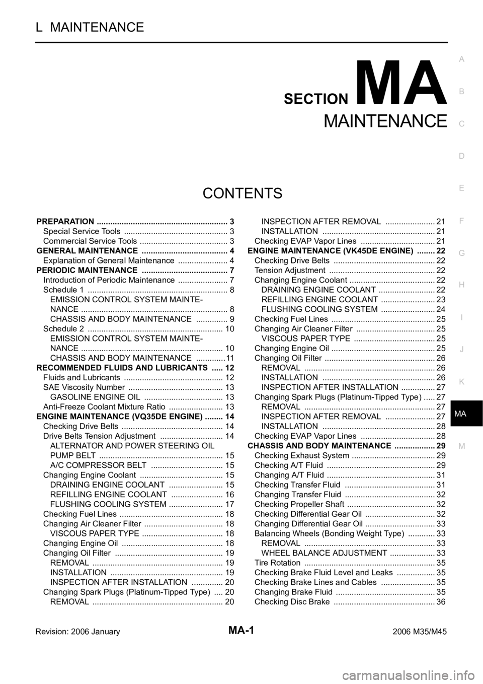
PREPARATION ........................................................... 3
Special Service Tools ............................................... 3
Commercial Service Tools ........................................ 3
GENERAL MAINTENANCE ....................................... 4
Explanation of General Maintenance ....................... 4
PERIODIC MAINTENANCE ....................................... 7
Introduction of Periodic Maintenance ....................... 7
Schedule 1 ............................................................... 8
EMISSION CONTROL SYSTEM MAINTE-
NANCE .................................................................. 8
CHASSIS AND BODY MAINTENANCE ............... 9
Schedule 2 ............................................................. 10
EMISSION CONTROL SYSTEM MAINTE-
NANCE ................................................................ 10
CHASSIS AND BODY MAINTENANCE .............. 11
RECOMMENDED FLUIDS AND LUBRICANTS ...... 12
Fluids and Lubricants ............................................. 12
SAE Viscosity Number ........................................... 13
GASOLINE ENGINE OIL .................................... 13
Anti-Freeze Coolant Mixture Ratio ......................... 13
ENGINE MAINTENANCE (VQ35DE ENGINE) ......... 14
Checking Drive Belts .............................................. 14
Drive Belts Tension Adjustment ............................. 14
ALTERNATOR AND POWER STEERING OIL
PUMP BELT ........................................................ 15
A/C COMPRESSOR BELT ................................. 15
Changing Engine Coolant ...................................... 15
DRAINING ENGINE COOLANT ......................... 15
REFILLING ENGINE COOLANT ........................ 16
FLUSHING COOLING SYSTEM ......................... 17
Checking Fuel Lines ............................................ ... 18
Changing Air Cleaner Filter .................................... 18
VISCOUS PAPER TYPE ..................................... 18
Changing Engine Oil .............................................. 18
Changing Oil Filter ................................................. 19
REMOVAL ........................................................
... 19
INSTALLATION ................................................... 19
INSPECTION AFTER INSTALLATION ............... 20
Changing Spark Plugs (Platinum-Tipped Type) ..... 20
REMOVAL ........................................................
... 20INSPECTION AFTER REMOVAL ....................... 21
INSTALLATION ................................................... 21
Checking EVAP Vapor Lines .................................. 21
ENGINE MAINTENANCE (VK45DE ENGINE) ......... 22
Checking Drive Belts .............................................. 22
Tension Adjustment .............................................
... 22
Changing Engine Coolant ....................................... 22
DRAINING ENGINE COOLANT .......................... 22
REFILLING ENGINE COOLANT ......................... 23
FLUSHING COOLING SYSTEM ......................... 24
Checking Fuel Lines ............................................ ... 25
Changing Air Cleaner Filter .................................... 25
VISCOUS PAPER TYPE ..................................... 25
Changing Engine Oil ............................................
... 25
Changing Oil Filter .................................................. 26
REMOVAL ........................................................
... 26
INSTALLATION ................................................... 26
INSPECTION AFTER INSTALLATION ................ 27
Changing Spark Plugs (Platinum-Tipped Type) ...... 27
REMOVAL ........................................................
... 27
INSPECTION AFTER REMOVAL ....................... 27
INSTALLATION ................................................... 28
Checking EVAP Vapor Lines .................................. 28
CHASSIS AND BODY MAINTENANCE ................... 29
Checking Exhaust System ...................................... 29
Checking A/T Fluid ................................................. 29
Changing A/T Fluid ................................................. 31
Checking Transfer Fluid ......................................... 31
Changing Transfer Fluid ......................................... 32
Checking Propeller Shaft ........................................ 32
Checking Differential Gear Oil ................................ 32
Changing Differential Gear Oil ................................ 33
Balancing Wheels (Bonding Weight Type) ............. 33
REMOVAL ........................................................
... 33
WHEEL BALANCE ADJUSTMENT ..................... 33
Tire Rotation ........................................................... 35
Checking Brake Fluid Level and Leaks .................. 35
Checking Brake Lines and Cables ......................... 35
Changing Brake Fluid ............................................. 35
Checking Disc Brake .............................................. 36
Page 4779 of 5621

MA-2Revision: 2006 January2006 M35/M45 ROTOR ................................................................ 36
CALIPER ............................................................. 36
PAD ..................................................................... 36
Checking Steering Gear and Linkage ..................... 36
STEERING GEAR ............................................... 36
STEERING LINKAGE .......................................... 36
Checking Power Steering Fluid and Lines .............. 37
Axle and Suspension Parts ..................................... 37
Drive Shaft .............................................................. 38
Lubricating Locks, Hinges and Hood Latch ............ 38
Checking Seat Belt, Buckles, Retractors, Anchors
and Adjusters .......................................................... 39
SERVICE DATA AND SPECIFICATIONS (SDS) ...... 40
Standard and Limit .................................................. 40
BELT DEFLECTION AND TENSION (VQ35DE) ... 40
BELT DEFLECTION AND TENSION (VK45DE) ... 40
ENGINE COOLANT CAPACITY (APPROXI-MATE) (VQ35DE) ................................................ 40
ENGINE COOLANT CAPACITY (APPROXI-
MATE) (VK45DE) ................................................. 40
RADIATOR ........................................................... 40
ENGINE OIL CAPACITY (APPROXIMATE)
(VQ35DE) ............................................................ 40
ENGINE OIL CAPACITY (APPROXIMATE)
(VK45DE) ............................................................. 41
SPARK PLUG (PLATINUM-TIPPED TYPE)
(VQ35DE) ............................................................ 41
SPARK PLUG (PLATINUM-TIPPED TYPE)
(VK45DE) ............................................................. 41
WHEEL BALANCE .............................................. 41
Page 4780 of 5621

PREPARATION
MA-3
C
D
E
F
G
H
I
J
K
MA
B
MA
Revision: 2006 January2006 M35/M45
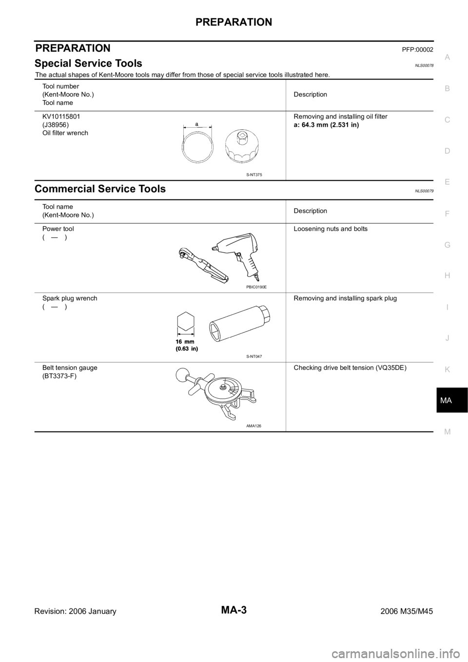
PREPARATIONPFP:00002
Special Service ToolsNLS00078
The actual shapes of Kent-Moore tools may differ from those of special service tools illustrated here.
Commercial Service ToolsNLS00079
Tool number
(Kent-Moore No.)
To o l n a m eDescription
KV10115801
(J38956)
Oil filter wrenchRemoving and installing oil filter
a: 64.3 mm (2.531 in)
S-NT375
To o l n a m e
(Kent-Moore No.)Description
Power tool
(—)Loosening nuts and bolts
Spark plug wrench
(—)Removing and installing spark plug
Belt tension gauge
(BT3373-F)Checking drive belt tension (VQ35DE)
PBIC0190E
S-NT047
AMA126
Page 4783 of 5621

MA-6
GENERAL MAINTENANCE
Revision: 2006 January2006 M35/M45
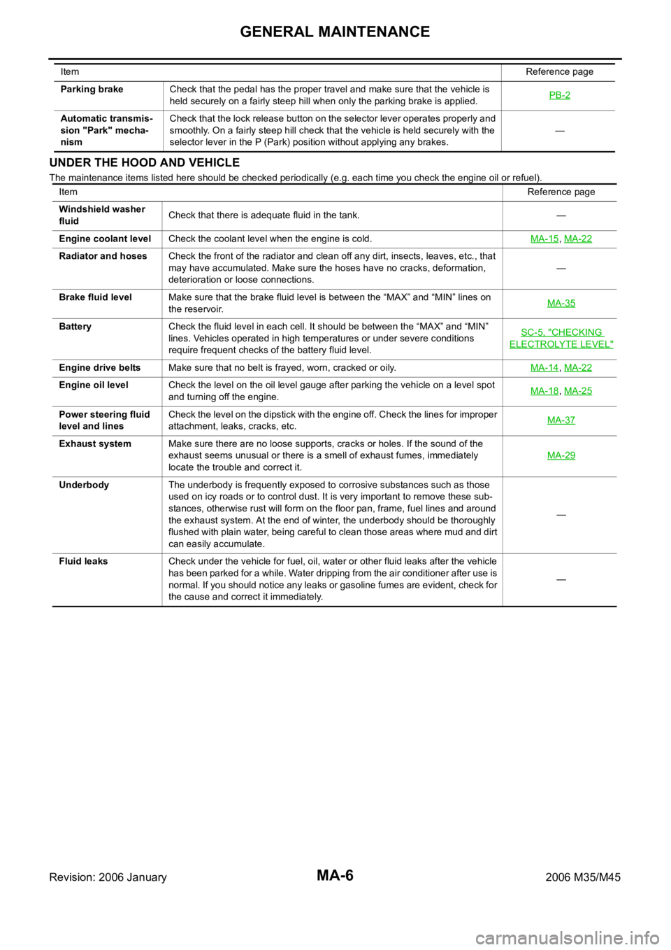
UNDER THE HOOD AND VEHICLE
The maintenance items listed here should be checked periodically (e.g. each time you check the engine oil or refuel). Parking brakeCheck that the pedal has the proper travel and make sure that the vehicle is
held securely on a fairly steep hill when only the parking brake is applied.PB-2
Automatic transmis-
sion "Park" mecha-
nismCheck that the lock release button on the selector lever operates properly and
smoothly. On a fairly steep hill check that the vehicle is held securely with the
selector lever in the P (Park) position without applying any brakes.— ItemReference page
ItemReference page
Windshield washer
fluidCheck that there is adequate fluid in the tank. —
Engine coolant levelCheck the coolant level when the engine is cold.MA-15
, MA-22
Radiator and hosesCheck the front of the radiator and clean off any dirt, insects, leaves, etc., that
may have accumulated. Make sure the hoses have no cracks, deformation,
deterioration or loose connections.—
Brake fluid levelMake sure that the brake fluid level is between the “MAX” and “MIN” lines on
the reservoir.MA-35
BatteryCheck the fluid level in each cell. It should be between the “MAX” and “MIN”
lines. Vehicles operated in high temperatures or under severe conditions
require frequent checks of the battery fluid level.SC-5, "
CHECKING
ELECTROLYTE LEVEL"
Engine drive beltsMake sure that no belt is frayed, worn, cracked or oily.MA-14, MA-22
Engine oil levelCheck the level on the oil level gauge after parking the vehicle on a level spot
and turning off the engine.MA-18, MA-25
Power steering fluid
level and linesCheck the level on the dipstick with the engine off. Check the lines for improper
attachment, leaks, cracks, etc.MA-37
Exhaust systemMake sure there are no loose supports, cracks or holes. If the sound of the
exhaust seems unusual or there is a smell of exhaust fumes, immediately
locate the trouble and correct it.MA-29
UnderbodyThe underbody is frequently exposed to corrosive substances such as those
used on icy roads or to control dust. It is very important to remove these sub-
stances, otherwise rust will form on the floor pan, frame, fuel lines and around
the exhaust system. At the end of winter, the underbody should be thoroughly
flushed with plain water, being careful to clean those areas where mud and dirt
can easily accumulate.—
Fluid leaksCheck under the vehicle for fuel, oil, water or other fluid leaks after the vehicle
has been parked for a while. Water dripping from the air conditioner after use is
normal. If you should notice any leaks or gasoline fumes are evident, check for
the cause and correct it immediately.—