2006 INFINITI M35 Oil
[x] Cancel search: OilPage 4852 of 5621

IPDM E/R (INTELLIGENT POWER DISTRIBUTION MODULE ENGINE ROOM)
PG-25
C
D
E
F
G
H
I
J
L
MA
B
PG
Revision: 2006 January2006 M35/M45
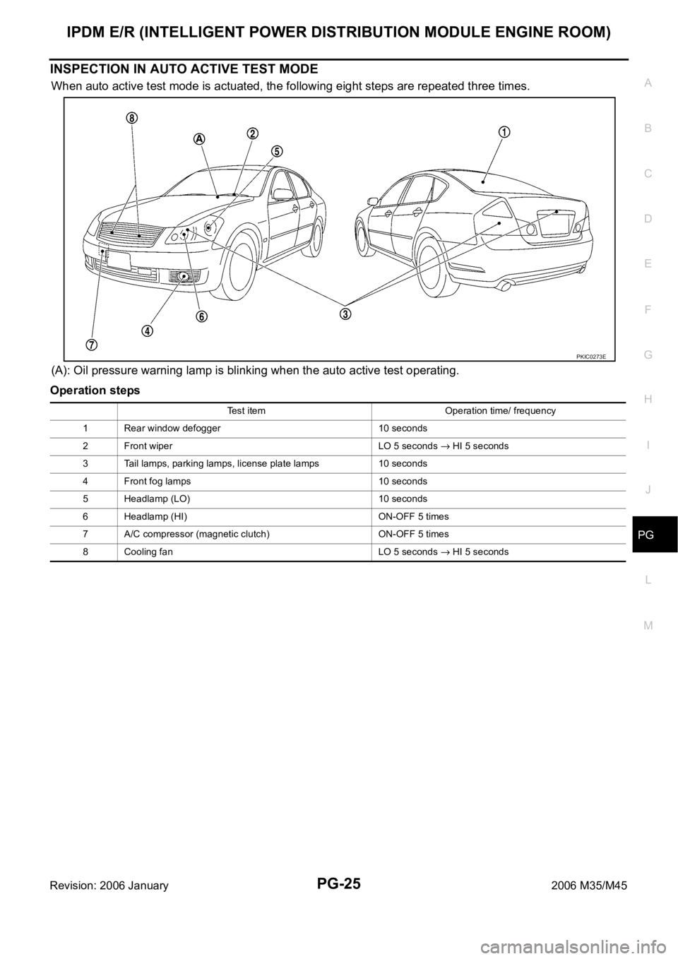
INSPECTION IN AUTO ACTIVE TEST MODE
When auto active test mode is actuated, the following eight steps are repeated three times.
(A): Oil pressure warning lamp is blinking when the auto active test operating.
Operation steps
PKIC0273E
Test item Operation time/ frequency
1 Rear window defogger 10 seconds
2 Front wiper LO 5 seconds
HI 5 seconds
3 Tail lamps, parking lamps, license plate lamps 10 seconds
4 Front fog lamps 10 seconds
5 Headlamp (LO) 10 seconds
6 Headlamp (HI) ON-OFF 5 times
7 A/C compressor (magnetic clutch) ON-OFF 5 times
8 Cooling fan LO 5 seconds
HI 5 seconds
Page 4854 of 5621

IPDM E/R (INTELLIGENT POWER DISTRIBUTION MODULE ENGINE ROOM)
PG-27
C
D
E
F
G
H
I
J
L
MA
B
PG
Revision: 2006 January2006 M35/M45
Cooling fan does not
operate.Perform auto active
test. Does cooling
fan operate?YES
ECM signal input circuit malfunction
CAN communication signal malfunction between ECM and IPDM E/R
NO
Cooling fan motor malfunction
Harness/connector malfunction between cooling fan motor and cooling fan
control module
Cooling fan control module malfunction
Harness/connector malfunction between IPDM E/R and cooling fan control
module
Cooling fan relay malfunction
Harness/connector malfunction between IPDM E/R and cooling fan relay
IPDM E/R malfunction
Oil pressure warning
lamp does not oper-
ate.Perform auto active
test. Does oil pres-
sure warning lamp
blink?YES
Harness/connector malfunction between IPDM E/R and oil pressure switch
Oil pressure switch malfunction
IPDM E/R malfunction
NO
CAN communication signal malfunction between IPDM E/R and unified meter
and A/C amp.
Combination meter malfunction Symptom Inspection contents Possible cause
Page 4921 of 5621

PG-94
HARNESS
Revision: 2006 January2006 M35/M45
ETC3 EC Electric Throttle Control Motor
F/FOG LT Front Fog Lamp
F/PUMP EC Fuel Pump
FPCM EC Fuel Pump Control Module
FTS AT A/T Fluid Temperature Sensor Circuit
FTTS EC Fuel Tank Temperature Sensor
FUELB1 EC Fuel Injection System Function (Bank 1)
FUELB2 EC Fuel Injection System Function (Bank 2)
H/LAMP LT Headlamp
HORN WW Horn
HSEAT SE Heated Seat
I/KEY BL Intelligent Key System
I/MIRR GW Inside Mirror (Auto Anti-Dazzling Mirror)
IATS EC Intake Air Temperature Sensor
ICC ACS Intelligent Cruise Control System
ICC/BS EC ICC Brake Switch
ICC/SW EC ICC Steering Switch
ICCBOF EC ICC Brake Switch
IGNSYS EC Ignition System
ILL LT Illumination
INJECT EC Injector
IVCB1 EC Intake Valve Timing Control Solenoid Valve Bank 1
IVCB2 EC Intake Valve Timing Control Solenoid Valve Bank 2
IVCSB1 EC Intake Valve Timing Control Position Sensor Bank 1
IVCSB2 EC Intake Valve Timing Control Position Sensor Bank 2
IVTB1 EC Intake Valve Timing Control System (Bank 1)
IVTB2 EC Intake Valve Timing Control System (Bank 2)
KS EC Knock Sensor
LDW DI Lane Departure Warning System
MAFS EC Mass Air Flow Sensor
MAIN AT Main Power Supply and Ground Circuit
MAIN EC Main Power Supply and Ground Circuit
METER DI Speedometer, Tachometer, Temp., Oil and Fuel Gauges
MIL/DL EC MIL & Data Link Connector
MIRROR GW Door Mirror
MMSW AT Manual Mode Switch
NATS BL Nissan Anti-Theft System
NONDTC AT Non-Detective Items
O2H2B1 EC Heated Oxygen Sensor 2 Heater Bank 1
O2H2B2 EC Heated Oxygen Sensor 2 Heater Bank 2
O2S2B1 EC Heated Oxygen Sensor 2 Bank 1
O2S2B2 EC Heated Oxygen Sensor 2 Bank 2
P/SCKT WW Power Socket
PDU PG Power Distribution Unit Code Section Wiring Diagram Name
Page 4954 of 5621

PS-1
POWER STEERING SYSTEM
G STEERING
CONTENTS
C
D
E
F
H
I
J
K
L
M
SECTION PS
A
B
PS
Revision: 2006 January2006 M35/M45
POWER STEERING SYSTEM
PRECAUTIONS .......................................................... 3
Precautions for Supplemental Restraint System
(SRS) “AIR BAG” and “SEAT BELT PRE-TEN-
SIONER” .................................................................. 3
Precautions Necessary for Steering Wheel Rotation
after Battery Disconnect ........................................... 3
OPERATION PROCEDURE ................................. 3
Precautions for Steering System .............................. 4
PREPARATION ........................................................... 5
Special Service Tools [SST] ..................................... 5
Commercial Service Tools ........................................ 6
NOISE, VIBRATION AND HARSHNESS (NVH)
TROUBLESHOOTING ................................................ 7
NVH Trouble Shooting Chart .................................... 7
POWER STEERING FLUID ........................................ 8
Checking Fluid Level ...........................................
..... 8
Checking Fluid Leakage ........................................... 8
Air Bleeding Hydraulic System ................................. 8
STEERING WHEEL .................................................. 10
On-Vehicle Inspection and Service ........................ 10
CHECKING CONDITION OF INSTALLATION .... 10
CHECKING STEERING WHEEL PLAY .............. 10
CHECKING NEUTRAL POSITION STEERING
WHEEL ............................................................... 10
CHECKING STEERING WHEEL TURNING
FORCE ................................................................ 10
CHECKING FRONT WHEEL TURNING ANGLE .... 11
Removal and Installation ........................................ 12
REMOVAL ........................................................
... 12
INSTALLATION ................................................... 12
STEERING COLUMN ............................................... 13
Removal and Installation ........................................ 13
COMPONENTS .................................................. 13
REMOVAL OF UPPER JOINT, COLLAR, HOLE
COVER SEAL, HOLE COVER, LOWER SHAFT
AND LOWER JOINT ........................................... 14
INSPECTION AFTER REMOVAL ....................... 14INSTALLATION OF UPPER JOINT, COLLAR,
HOLE COVER SEAL, HOLE COVER, LOWER
SHAFT AND LOWER JOINT .............................. 14
REMOVAL OF STEERING COLUMN ASSEM-
BLY ...................................................................... 15
INSPECTION AFTER REMOVAL ....................... 16
INSTALLATION OF STEERING COLUMN
ASSEMBLY ......................................................... 16
INSPECTION AFTER INSTALLATION ................ 16
Disassembly and Assembly .................................... 17
COMPONENTS ................................................... 17
DISASSEMBLY ................................................... 17
INSPECTION AFTER DISASSEMBLY ................ 17
ASSEMBLY ......................................................... 17
INSPECTION AFTER ASSEMBLY ...................... 17
POWER STEERING GEAR ...................................... 18
Removal and Installation ........................................ 18
COMPONENTS ................................................... 18
REMOVAL ........................................................
... 18
INSTALLATION ................................................... 19
INSPECTION AFTER INSTALLATION ................ 19
Disassembly and Assembly .................................
... 20
COMPONENTS ................................................... 20
DISASSEMBLY ................................................... 21
INSPECTION AFTER DISASSEMBLY ................ 22
ASSEMBLY ......................................................... 24
POWER STEERING OIL PUMP ............................... 29
On-Vehicle Inspection and Service ......................... 29
CHECKING RELIEF OIL PRESSURE ................ 29
Removal and Installation ........................................ 29
REMOVAL ........................................................
... 29
INSTALLATION ................................................... 29
Disassembly and Assembly (Models with VK45DE) ... 30
COMPONENTS ................................................... 30
INSPECTION BEFORE DISASSEMBLY ............. 30
DISASSEMBLY ................................................... 31
INSPECTION AFTER DISASSEMBLY ................ 31
Page 4955 of 5621

PS-2Revision: 2006 January2006 M35/M45 ASSEMBLY ......................................................... 32
Disassembly and Assembly (Models with VQ35DE) ... 34
COMPONENTS ................................................... 34
INSPECTION BEFORE DISASSEMBLY ............. 34
DISASSEMBLY ................................................... 35
INSPECTION AFTER DISASSEMBLY ................ 35
ASSEMBLY ......................................................... 36
HYDRAULIC LINE .................................................
... 38
Components ........................................................... 38
VQ35DE 2WD MODELS ..................................... 38
VQ35DE AWD MODELS ..................................... 40VK45DE MODELS ............................................... 42
Removal and Installation ......................................... 43
SERVICE DATA AND SPECIFICATIONS (SDS) ...... 44
Steering Wheel ........................................................ 44
Steering Angle ......................................................... 44
Steering Column ..................................................... 44
Steering Outer Socket and Inner Socket ................. 44
Steering Gear .......................................................... 45
Oil Pump ................................................................. 45
Steering Fluid .......................................................... 45
Page 4958 of 5621
![INFINITI M35 2006 Factory Service Manual PREPARATION
PS-5
C
D
E
F
H
I
J
K
L
MA
B
PS
Revision: 2006 January2006 M35/M45
PREPARATIONPFP:00002
Special Service Tools [SST]NGS000D2
The actual shapes of Kent-Moore tools may differ from those of sp INFINITI M35 2006 Factory Service Manual PREPARATION
PS-5
C
D
E
F
H
I
J
K
L
MA
B
PS
Revision: 2006 January2006 M35/M45
PREPARATIONPFP:00002
Special Service Tools [SST]NGS000D2
The actual shapes of Kent-Moore tools may differ from those of sp](/manual-img/42/57023/w960_57023-4957.png)
PREPARATION
PS-5
C
D
E
F
H
I
J
K
L
MA
B
PS
Revision: 2006 January2006 M35/M45
PREPARATIONPFP:00002
Special Service Tools [SST]NGS000D2
The actual shapes of Kent-Moore tools may differ from those of special service tools illustrated here.
Tool number
(Kent-Moore No.)
Tool nameDescription
ST27180001
(J-25726-A)
Steering wheel pullerRemoving steering wheel
ST3127S000
(See J-25765-A)
Preload gauge
1. GG9103000
(J-25765-A)
To r q u e w r e n c h
2. HT62940000
(–)
Socket adapter
3. HT62900000
(–)
Socket adapterInspecting of rotating torque for ball joint
KV48104400
(–)
Teflon ring correcting tool
a: 50 mm (1.97 in) dia.
b: 36 mm (1.42 in) dia.
c: 100 mm (3.94 in)Installing rack Teflon ring
KV48103400
(–)
Preload adapterInspecting rotating torque
KV48103500
(J-26357)
Pressure gaugeMeasuring oil pump relief pressure
S-NT544
S-NT541
S-NT550
ZZA0824D
S-NT547
Page 4959 of 5621

PS-6
PREPARATION
Revision: 2006 January2006 M35/M45
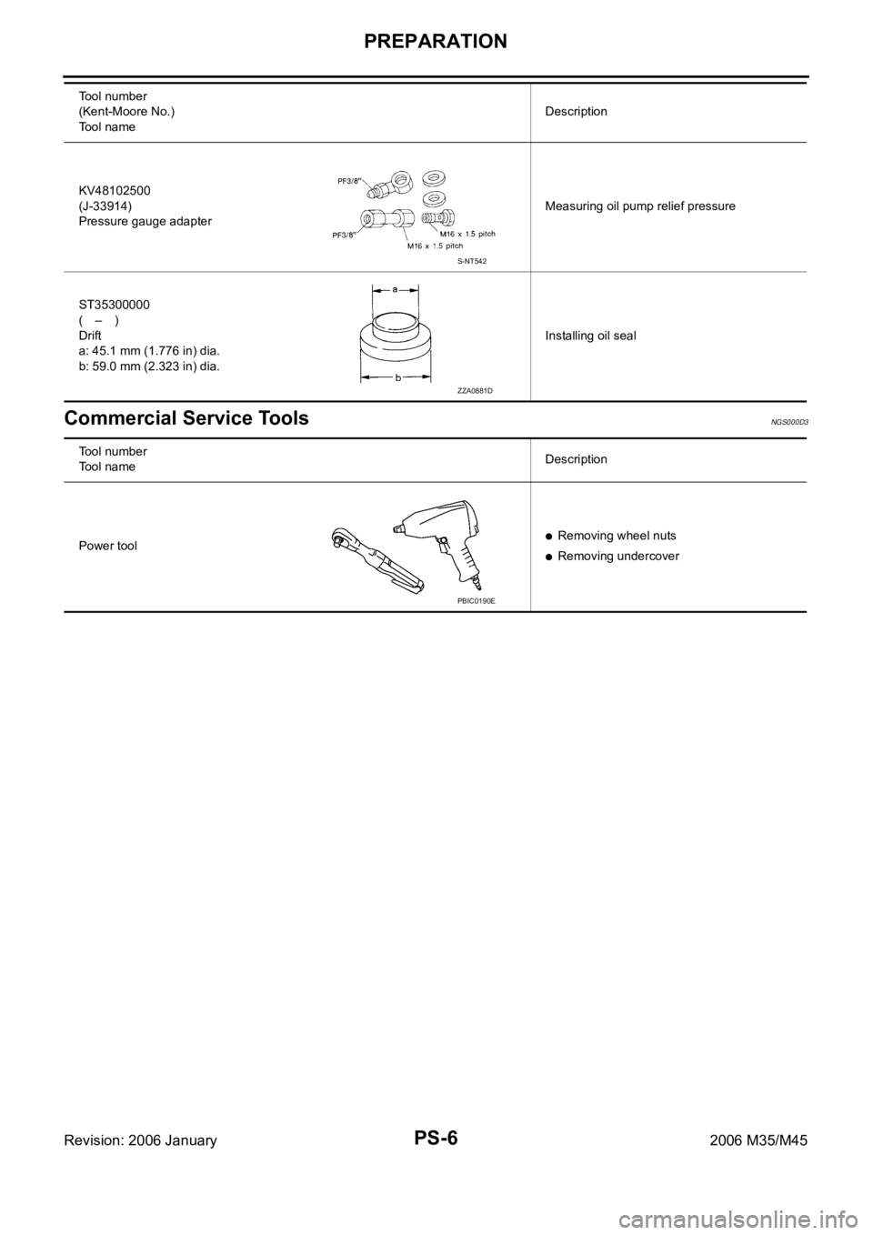
Commercial Service ToolsNGS000D3
KV48102500
(J-33914)
Pressure gauge adapterMeasuring oil pump relief pressure
ST35300000
(–)
Drift
a: 45.1 mm (1.776 in) dia.
b: 59.0 mm (2.323 in) dia.Installing oil seal Tool number
(Kent-Moore No.)
Tool nameDescription
S-NT542
ZZA0881D
Tool number
Tool nameDescription
Power tool
Removing wheel nuts
Removing undercover
PBIC0190E
Page 4961 of 5621

PS-8
POWER STEERING FLUID
Revision: 2006 January2006 M35/M45
POWER STEERING FLUIDPFP:KLF20
Checking Fluid LevelNGS000D5
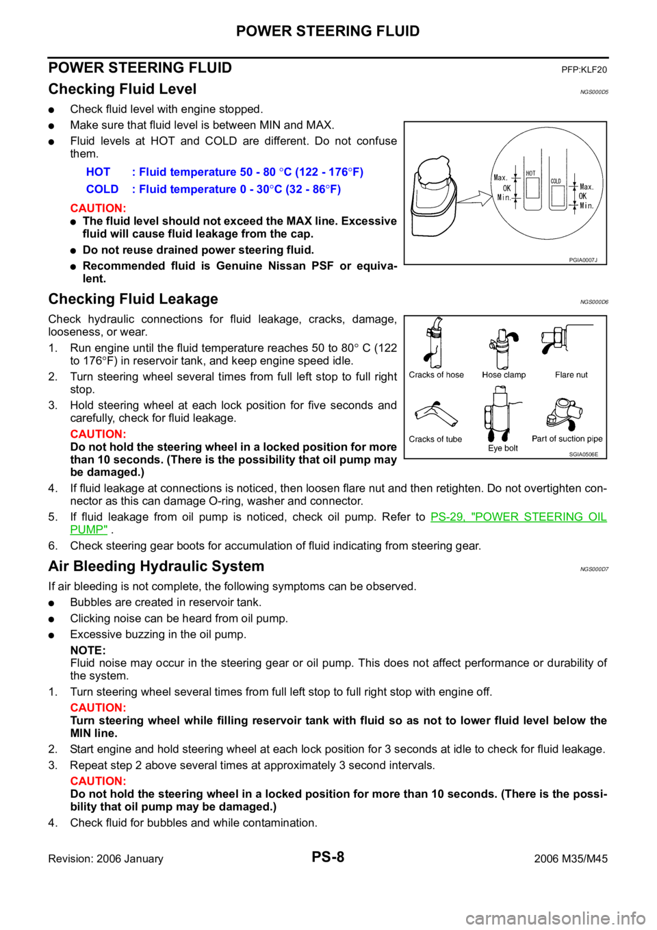
Check fluid level with engine stopped.
Make sure that fluid level is between MIN and MAX.
Fluid levels at HOT and COLD are different. Do not confuse
them.
CAUTION:
The fluid level should not exceed the MAX line. Excessive
fluid will cause fluid leakage from the cap.
Do not reuse drained power steering fluid.
Recommended fluid is Genuine Nissan PSF or equiva-
lent.
Checking Fluid LeakageNGS000D6
Check hydraulic connections for fluid leakage, cracks, damage,
looseness, or wear.
1. Run engine until the fluid temperature reaches 50 to 80
C (122
to 176
F) in reservoir tank, and keep engine speed idle.
2. Turn steering wheel several times from full left stop to full right
stop.
3. Hold steering wheel at each lock position for five seconds and
carefully, check for fluid leakage.
CAUTION:
Do not hold the steering wheel in a locked position for more
than 10 seconds. (There is the possibility that oil pump may
be damaged.)
4. If fluid leakage at connections is noticed, then loosen flare nut and then retighten. Do not overtighten con-
nector as this can damage O-ring, washer and connector.
5. If fluid leakage from oil pump is noticed, check oil pump. Refer to PS-29, "
POWER STEERING OIL
PUMP" .
6. Check steering gear boots for accumulation of fluid indicating from steering gear.
Air Bleeding Hydraulic SystemNGS000D7
If air bleeding is not complete, the following symptoms can be observed.
Bubbles are created in reservoir tank.
Clicking noise can be heard from oil pump.
Excessive buzzing in the oil pump.
NOTE:
Fluid noise may occur in the steering gear or oil pump. This does not affect performance or durability of
the system.
1. Turn steering wheel several times from full left stop to full right stop with engine off.
CAUTION:
Turn steering wheel while filling reservoir tank with fluid so as not to lower fluid level below the
MIN line.
2. Start engine and hold steering wheel at each lock position for 3 seconds at idle to check for fluid leakage.
3. Repeat step 2 above several times at approximately 3 second intervals.
CAUTION:
Do not hold the steering wheel in a locked position for more than 10 seconds. (There is the possi-
bility that oil pump may be damaged.)
4. Check fluid for bubbles and while contamination.HOT : Fluid temperature 50 - 80
C (122 - 176F)
COLD : Fluid temperature 0 - 30
C (32 - 86F)
PGIA0007J
SGIA0506E