2006 INFINITI M35 service
[x] Cancel search: servicePage 3412 of 5621
SERVICE DATA AND SPECIFICATIONS (SDS)
FFD-35
C
E
F
G
H
I
J
K
L
MA
B
FFD
Revision: 2006 January2006 M35/M45
SERVICE DATA AND SPECIFICATIONS (SDS)PFP:00030
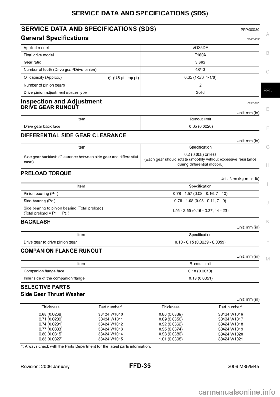
General SpecificationsNDS000EW
Inspection and AdjustmentNDS000EX
DRIVE GEAR RUNOUT
Unit: mm (in)
DIFFERENTIAL SIDE GEAR CLEARANCE
Unit: mm (in)
PRELOAD TORQUE
Unit: Nꞏm (kg-m, in-lb)
BACKLASH
Unit: mm (in)
COMPANION FLANGE RUNOUT
Unit: mm (in)
SELECTIVE PARTS
Side Gear Thrust Washer
Unit: mm (in)
*: Always check with the Parts Department for the latest parts information. Applied modelVQ35DE
Final drive modelF160A
Gear ratio3.692
Number of teeth (Drive gear/Drive pinion) 48/13
Oil capacity (Approx.)
(US pt, lmp pt)0.65 (1-3/8, 1-1/8)
Number of pinion gears2
Drive pinion adjustment spacer type Solid
Item Runout limit
Drive gear back face 0.05 (0.0020)
Item Specification
Side gear backlash (Clearance between side gear and differential
case)0.2 (0.008) or less
(Each gear should rotate smoothly without excessive resistance
during differential motion.)
Item Specification
Pinion bearing (P
1 ) 0.78 - 1.57 (0.08 - 0.16, 7 - 13)
Side bearing (P
2 ) 0.78 - 1.08 (0.08 - 0.11, 7 - 9)
Side bearing to pinion bearing (Total preload)
(Total preload = P
1 + P2 )1.56 - 2.65 (0.16 - 0.27, 14 - 23)
Item Specification
Drive gear to drive pinion gear 0.10 - 0.15 (0.0039 - 0.0059)
Item Runout limit
Companion flange face 0.18 (0.0070)
Inner side of the companion flange 0.13 (0.0051)
Thickness Part number* Thickness Part number*
0.68 (0.0268)
0.71 (0.0280)
0.74 (0.0291)
0.77 (0.0303)
0.80 (0.0315)
0.83 (0.0327)38424 W1010
38424 W1011
38424 W1012
38424 W1013
38424 W1014
38424 W10150.86 (0.0339)
0.89 (0.0350)
0.92 (0.0362)
0.95 (0.0374)
0.98 (0.0386)
1.01 (0.0398)38424 W1016
38424 W1017
38424 W1018
38424 W1019
38424 W1020
38424 W1021
Page 3413 of 5621
FFD-36
SERVICE DATA AND SPECIFICATIONS (SDS)
Revision: 2006 January2006 M35/M45
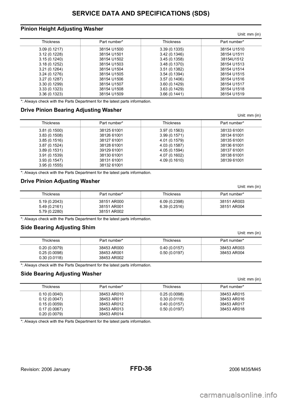
Pinion Height Adjusting Washer
Unit: mm (in)
*: Always check with the Parts Department for the latest parts information.
Drive Pinion Bearing Adjusting Washer
Unit: mm (in)
*: Always check with the Parts Department for the latest parts information.
Drive Pinion Adjusting Washer
Unit: mm (in)
*: Always check with the Parts Department for the latest parts information.
Side Bearing Adjusting Shim
Unit: mm (in)
*: Always check with the Parts Department for the latest parts information.
Side Bearing Adjusting Washer
Unit: mm (in)
*: Always check with the Parts Department for the latest parts information. Thickness Part number* Thickness Part number*
3.09 (0.1217)
3.12 (0.1228)
3.15 (0.1240)
3.18 (0.1252)
3.21 (0.1264)
3.24 (0.1276)
3.27 (0.1287)
3.30 (0.1299)
3.33 (0.1323)
3.36 (0.1323)38154 U1500
38154 U1501
38154 U1502
38154 U1503
38154 U1504
38154 U1505
38154 U1506
38154 U1507
38154 U1508
38154 U15093.39 (0.1335)
3.42 (0.1346)
3.45 (0.1358)
3.48 (0.1370)
3.51 (0.1382)
3.54 (0.1394)
3.57 (0.1406)
3.60 (0.1429)
3.63 (0.1429)
3.66 (0.1441)38154 U1510
38154 U1511
38154U1512
38154 U1513
38154 U1514
38154 U1515
38154 U1516
38154 U1517
38154 U1518
38154 U1519
Thickness Part number* Thickness Part number*
3.81 (0.1500)
3.83 (0.1508)
3.85 (0.1516)
3.87 (0.1524)
3.89 (0.1531)
3.91 (0.1539)
3.93 (0.1547)
3.95 (0.1555)38125 61001
38126 61001
38127 61001
38128 61001
39129 61001
38130 61001
38131 61001
38132 610013.97 (0.1563)
3.99 (0.1571)
4.01 (0.1579)
4.03 (0.1587)
4.05 (0.1594)
4.07 (0.1602)
4.09 (0.1610)38133 61001
38134 61001
38135 61001
38136 61001
38137 61001
38138 61001
38139 61001
Thickness Part number* Thickness Part number*
5.19 (0.2043)
5.49 (0.2161)
5.79 (0.2280)38151 AR000
38151 AR001
38151 AR0026.09 (0.2398)
6.39 (0.2516)38151 AR003
38151 AR004
Thickness Part number* Thickness Part number*
0.20 (0.0079)
0.25 (0.0098)
0.30 (0.0118)38453 AR000
38453 AR001
38453 AR0020.40 (0.0157)
0.50 (0.0197)38453 AR003
38453 AR004
Thickness Part number* Thickness Part number*
0.10 (0.0040)
0.12 (0.0047)
0.15 (0.0059)
0.17 (0.0067)
0.20 (0.0079)38453 AR010
38453 AR011
38453 AR012
38453 AR013
38453 AR0140.25 (0.0098)
0.30 (0.0118)
0.40 (0.0157)
0.50 (0.0197)38453 AR015
38453 AR016
38453 AR017
38453 AR018
Page 3414 of 5621
FL-1
FUEL SYSTEM
B ENGINE
CONTENTS
C
D
E
F
G
H
I
J
K
L
M
SECTION FL
A
FL
Revision: 2006 January2006 M35/M45
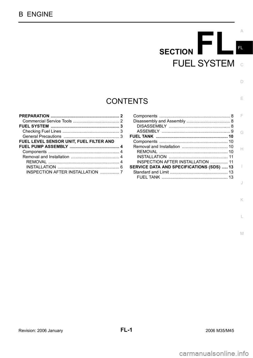
FUEL SYSTEM
PREPARATION ........................................................... 2
Commercial Service Tools ........................................ 2
FUEL SYSTEM ........................................................... 3
Checking Fuel Lines ............................................ ..... 3
General Precautions ................................................ 3
FUEL LEVEL SENSOR UNIT, FUEL FILTER AND
FUEL PUMP ASSEMBLY ........................................... 4
Components ............................................................. 4
Removal and Installation .......................................... 4
REMOVAL ........................................................
..... 4
INSTALLATION ..................................................... 6
INSPECTION AFTER INSTALLATION ................. 7Components ............................................................. 8
Disassembly and Assembly ...................................... 8
DISASSEMBLY ..................................................... 8
ASSEMBLY ........................................................... 9
FUEL TANK .............................................................. 10
Components ........................................................... 10
Removal and Installation ........................................ 10
REMOVAL ........................................................
... 10
INSTALLATION ................................................... 11
INSPECTION AFTER INSTALLATION ................ 11
SERVICE DATA AND SPECIFICATIONS (SDS) ...... 13
Standard and Limit .................................................. 13
FUEL TANK ...................................................... ... 13
Page 3415 of 5621
FL-2
PREPARATION
Revision: 2006 January2006 M35/M45
PREPARATIONPFP:00002
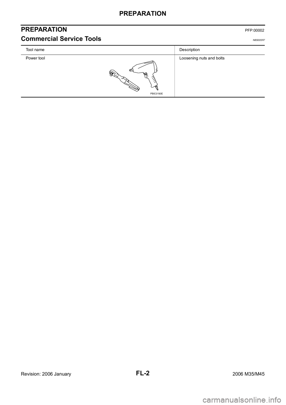
Commercial Service ToolsNBS005R7
Tool nameDescription
Power toolLoosening nuts and bolts
PBIC0190E
Page 3426 of 5621
SERVICE DATA AND SPECIFICATIONS (SDS)
FL-13
C
D
E
F
G
H
I
J
K
L
MA
FL
Revision: 2006 January2006 M35/M45
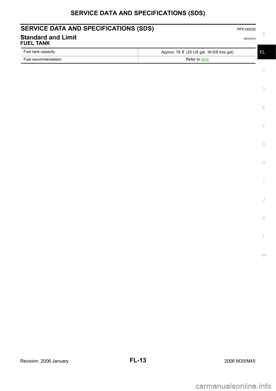
SERVICE DATA AND SPECIFICATIONS (SDS)PFP:00030
Standard and LimitNBS005RG
FUEL TANK
Fuel tank capacity
Approx. 76 (20 US gal, 16-5/8 Imp gal)
Fuel recommendation Refer to GI-6
Page 3427 of 5621

FL-14
SERVICE DATA AND SPECIFICATIONS (SDS)
Revision: 2006 January2006 M35/M45
Page 3428 of 5621
FSU-1
FRONT SUSPENSION
E SUSPENSION
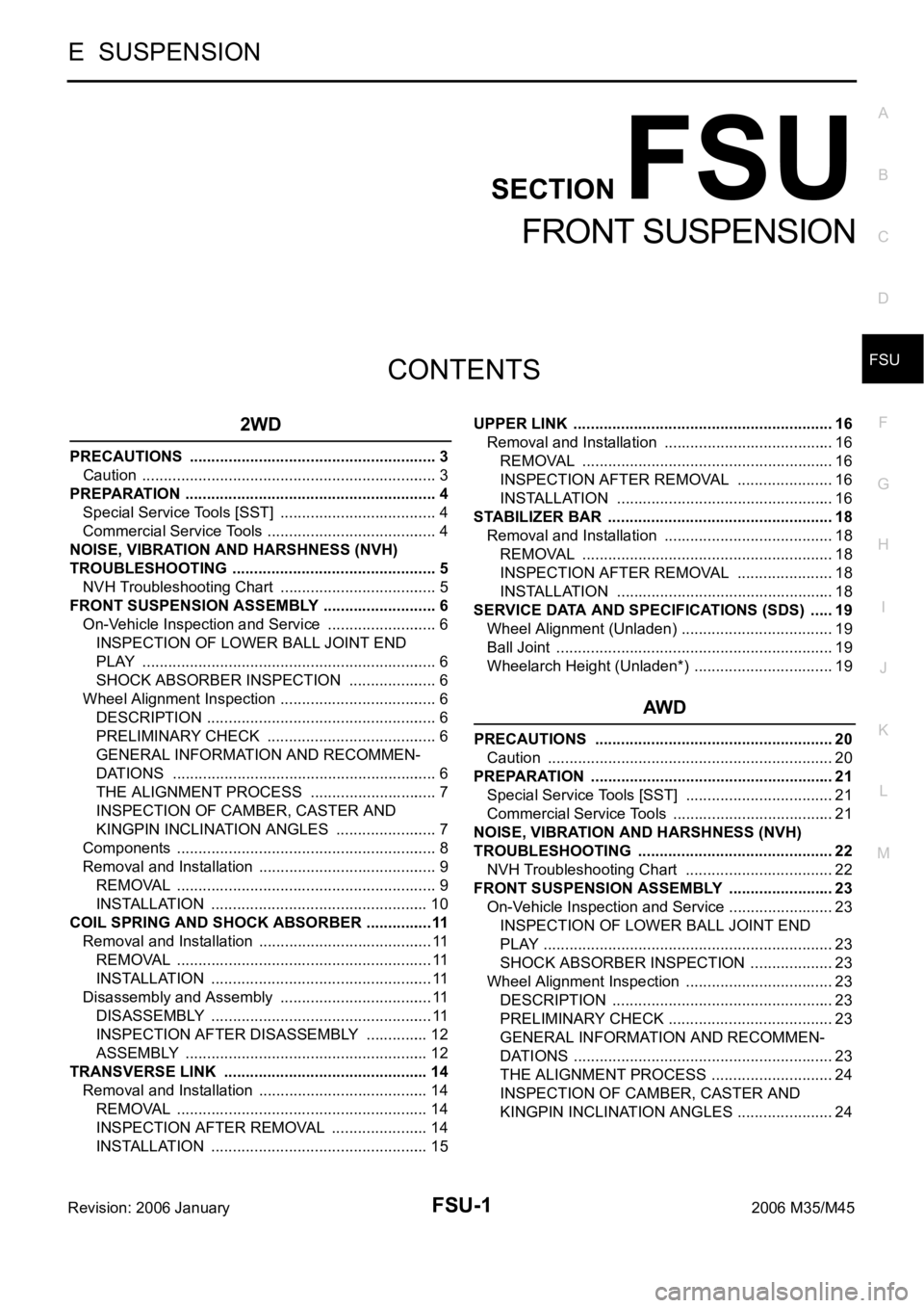
CONTENTS
C
D
F
G
H
I
J
K
L
M
SECTION FSU
A
B
FSU
Revision: 2006 January2006 M35/M45
FRONT SUSPENSION
2WD
PRECAUTIONS .......................................................... 3
Caution ..................................................................... 3
PREPARATION ........................................................... 4
Special Service Tools [SST] ..................................... 4
Commercial Service Tools ........................................ 4
NOISE, VIBRATION AND HARSHNESS (NVH)
TROUBLESHOOTING ................................................ 5
NVH Troubleshooting Chart ..................................... 5
FRONT SUSPENSION ASSEMBLY ........................... 6
On-Vehicle Inspection and Service .......................... 6
INSPECTION OF LOWER BALL JOINT END
PLAY ..................................................................... 6
SHOCK ABSORBER INSPECTION ..................... 6
Wheel Alignment Inspection ..................................... 6
DESCRIPTION ...................................................... 6
PRELIMINARY CHECK ........................................ 6
GENERAL INFORMATION AND RECOMMEN-
DATIONS .............................................................. 6
THE ALIGNMENT PROCESS .............................. 7
INSPECTION OF CAMBER, CASTER AND
KINGPIN INCLINATION ANGLES ........................ 7
Components ............................................................. 8
Removal and Installation .......................................... 9
REMOVAL ........................................................
..... 9
INSTALLATION ................................................... 10
COIL SPRING AND SHOCK ABSORBER ................11
Removal and Installation ......................................... 11
REMOVAL ........................................................
.... 11
INSTALLATION .................................................... 11
Disassembly and Assembly .................................... 11
DISASSEMBLY .................................................... 11
INSPECTION AFTER DISASSEMBLY ............... 12
ASSEMBLY ......................................................... 12
TRANSVERSE LINK ................................................ 14
Removal and Installation ........................................ 14
REMOVAL ........................................................
... 14
INSPECTION AFTER REMOVAL ....................... 14
INSTALLATION ................................................... 15UPPER LINK ............................................................. 16
Removal and Installation ........................................ 16
REMOVAL ........................................................
... 16
INSPECTION AFTER REMOVAL ....................... 16
INSTALLATION ................................................... 16
STABILIZER BAR ..................................................... 18
Removal and Installation ........................................ 18
REMOVAL ........................................................
... 18
INSPECTION AFTER REMOVAL ....................... 18
INSTALLATION ................................................... 18
SERVICE DATA AND SPECIFICATIONS (SDS) ...... 19
Wheel Alignment (Unladen) .................................... 19
Ball Joint ....................................................
............. 19
Wheelarch Height (Unladen*) ................................. 19
AWD
PRECAUTIONS ........................................................ 20
Caution ................................................................... 20
PREPARATION ......................................................... 21
Special Service Tools [SST] ................................... 21
Commercial Service Tools ...................................... 21
NOISE, VIBRATION AND HARSHNESS (NVH)
TROUBLESHOOTING .............................................. 22
NVH Troubleshooting Chart ................................... 22
FRONT SUSPENSION ASSEMBLY ......................... 23
On-Vehicle Inspection and Service ......................... 23
INSPECTION OF LOWER BALL JOINT END
PLAY .................................................................... 23
SHOCK ABSORBER INSPECTION .................... 23
Wheel Alignment Inspection ................................... 23
DESCRIPTION .................................................... 23
PRELIMINARY CHECK ....................................... 23
GENERAL INFORMATION AND RECOMMEN-
DATIONS ............................................................. 23
THE ALIGNMENT PROCESS ............................. 24
INSPECTION OF CAMBER, CASTER AND
KINGPIN INCLINATION ANGLES ....................... 24
Page 3429 of 5621
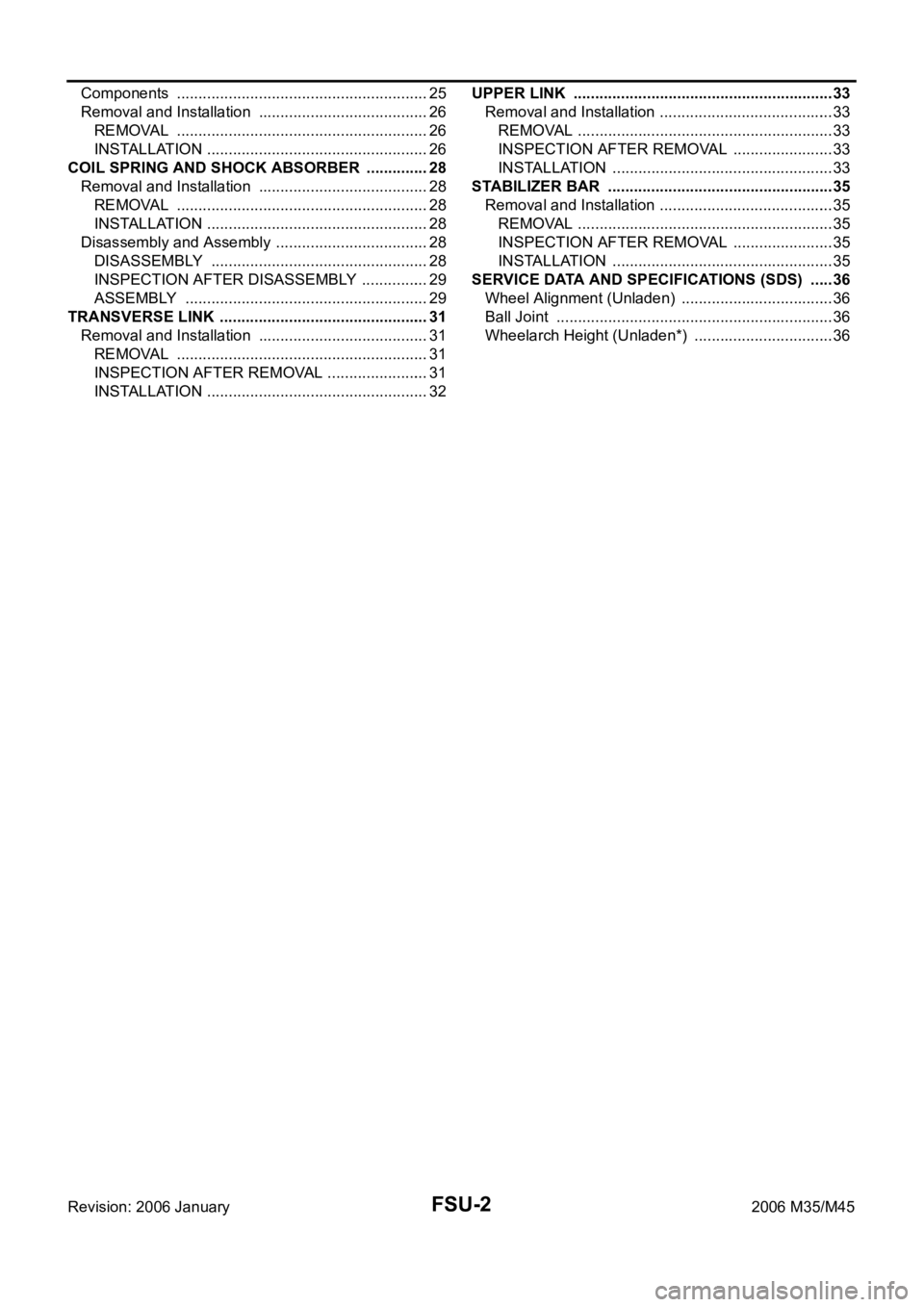
FSU-2Revision: 2006 January2006 M35/M45 Components ........................................................... 25
Removal and Installation ........................................ 26
REMOVAL ........................................................
... 26
INSTALLATION .................................................... 26
COIL SPRING AND SHOCK ABSORBER ............... 28
Removal and Installation ........................................ 28
REMOVAL ........................................................
... 28
INSTALLATION .................................................... 28
Disassembly and Assembly .................................... 28
DISASSEMBLY ................................................... 28
INSPECTION AFTER DISASSEMBLY ................ 29
ASSEMBLY ......................................................... 29
TRANSVERSE LINK ................................................. 31
Removal and Installation ........................................ 31
REMOVAL ........................................................
... 31
INSPECTION AFTER REMOVAL ........................ 31
INSTALLATION .................................................... 32UPPER LINK ............................................................. 33
Removal and Installation ......................................... 33
REMOVAL ............................................................ 33
INSPECTION AFTER REMOVAL ........................ 33
INSTALLATION .................................................... 33
STABILIZER BAR ..................................................... 35
Removal and Installation ......................................... 35
REMOVAL ............................................................ 35
INSPECTION AFTER REMOVAL ........................ 35
INSTALLATION .................................................... 35
SERVICE DATA AND SPECIFICATIONS (SDS) ...... 36
Wheel Alignment (Unladen) .................................... 36
Ball Joint ................................................................. 36
Wheelarch Height (Unladen*) ................................. 36