2006 INFINITI M35 weight
[x] Cancel search: weightPage 3313 of 5621
![INFINITI M35 2006 Factory Service Manual EM-250
[VK45DE]
CYLINDER BLOCK
Revision: 2006 January2006 M35/M45
Disassembly and AssemblyNBS004PN
DISASSEMBLY
NOTE:
Explained here is how to disassemble with engine stand supporting transmission su INFINITI M35 2006 Factory Service Manual EM-250
[VK45DE]
CYLINDER BLOCK
Revision: 2006 January2006 M35/M45
Disassembly and AssemblyNBS004PN
DISASSEMBLY
NOTE:
Explained here is how to disassemble with engine stand supporting transmission su](/manual-img/42/57023/w960_57023-3312.png)
EM-250
[VK45DE]
CYLINDER BLOCK
Revision: 2006 January2006 M35/M45
Disassembly and AssemblyNBS004PN
DISASSEMBLY
NOTE:
Explained here is how to disassemble with engine stand supporting transmission surface. When using differ-
ent type of engine stand, note with difference in steps and etc.
1. Remove engine assembly from vehicle, and separate front suspension member, transmission from
engine. Refer to EM-244, "
ENGINE ASSEMBLY" .
2. Remove the parts that may restrict installation of engine to widely use engine stand.
NOTE:
The procedure is described assuming that you use widely use engine holding the surface, to which trans-
mission is installed.
a. Remove drive plate.
Holding ring gear with ring gear stopper (SST).
Loosen mounting bolts diagonally order.
CAUTION:
Do not disassemble drive plate.
Do not place drive plate with signal plate facing down.
When handling signal plate, take care not to damage or
scratch it.
Handle signal plate in a manner that prevents it from
becoming magnetized.
b. Remove rear plate.
3. Lift engine with hoist to install it onto widely use engine stand.
CAUTION:
Use engine stand that has a load capacity [approximately 240kg (529 lb) or more] large enough for
supporting the engine weight.
If the load capacity of stand is not adequate, remove the following parts beforehand to reduce the
potential risk of overturning stand.
–Intake manifolds (upper and lower); Refer to EM-179, "INTAKE MANIFOLD" .
–Exhaust manifold and three way catalyst; Refer to EM-183, "EXHAUST MANIFOLD AND THREE WAY
CATALYST" .
13. Piston pin 14. Connecting rod bearing 15. Connecting rod bearing cap
16. Block heater protector 17. Connector cap 18. Cylinder block heater
19. Gasket 20. Main bearing cap 21. Thrust bearing
22. Main bearing 23. Rear plate 24. Crankshaft
25. Pilot convertor 26. Drive plate 27. Thrust bearing
28. Side bolt 29. Reinforcement plate 30. Crankshaft position sensor (POS)
31. O-ring 32. Rear oil seal 33. Rear oil seal retainer
PBIC1656E
PBIC2367E
Page 3314 of 5621
![INFINITI M35 2006 Factory Service Manual CYLINDER BLOCK
EM-251
[VK45DE]
C
D
E
F
G
H
I
J
K
L
MA
EM
Revision: 2006 January2006 M35/M45
–Fuel tube and fuel injector assembly; Refer to EM-193, "FUEL INJECTOR AND FUEL TUBE" .
–Ignitio INFINITI M35 2006 Factory Service Manual CYLINDER BLOCK
EM-251
[VK45DE]
C
D
E
F
G
H
I
J
K
L
MA
EM
Revision: 2006 January2006 M35/M45
–Fuel tube and fuel injector assembly; Refer to EM-193, "FUEL INJECTOR AND FUEL TUBE" .
–Ignitio](/manual-img/42/57023/w960_57023-3313.png)
CYLINDER BLOCK
EM-251
[VK45DE]
C
D
E
F
G
H
I
J
K
L
MA
EM
Revision: 2006 January2006 M35/M45
–Fuel tube and fuel injector assembly; Refer to EM-193, "FUEL INJECTOR AND FUEL TUBE" .
–Ignition coil; Refer to EM-190, "IGNITION COIL" .
–Rocker cover; Refer to EM-199, "ROCKER COVER" .
–Other removable brackets
NOTE:
The figure shows an example of widely use engine stand that
can hold mating surface of transmission with drive plate and rear
plate removed.
CAUTION:
Before removing the hanging chains, make sure the engine
stand is stable and there is no risk of overturning.
4. Drain engine oil. Refer to LU-28, "
Changing Engine Oil" .
5. Drain engine coolant from inside engine by removing water
drain plugs “B” as shown in the figure.
6. Remove oil pan and oil strainer; Refer to EM-187, "
OIL PAN AND OIL STRAINER" .
7. Remove crankshaft pulley as follows:
a. Lock crankshaft with a hammer handle or similar tool to loosen
crankshaft bolt.
b. Pull crankshaft pulley with both hands to remove it.
CAUTION:
Do not remove crankshaft pulley bolt. Keep loosened
crankshaft pulley bolt in place to protect removed crank-
shaft pulley from dropping.
Do not remove balance weight (inner hexagon bolt) at the
front of crankshaft pulley.
8. Remove the following parts and related parts (The parts listed in step 3 are not included here.)
Front cover and timing chain; Refer to EM-203, "TIMING CHAIN" .
Camshaft; Refer to EM-215, "CAMSHAFT" .
Cylinder head; Refer to EM-233, "CYLINDER HEAD" .
9. Remove knock sensor.
CAUTION:
Carefully handle sensor, avoiding shocks.
10. Remove piston and connecting rod assembly as follows:
Before removing piston and connecting rod assembly, check the connecting rod side clearance. Refer
to EM-266, "
CONNECTING ROD SIDE CLEARANCE" .
a. Position crankshaft pin corresponding to connecting rod to be removed onto the bottom dead center.
b. Remove connecting rod bearing cap.
PBIC0085E
PBIC1265E
PBIC0053E
Page 3316 of 5621
![INFINITI M35 2006 Factory Service Manual CYLINDER BLOCK
EM-253
[VK45DE]
C
D
E
F
G
H
I
J
K
L
MA
EM
Revision: 2006 January2006 M35/M45
c. Push out piston pin with stick of outer diameter approximately 20
mm (0.8 in).
14. Remove rear oil seal r INFINITI M35 2006 Factory Service Manual CYLINDER BLOCK
EM-253
[VK45DE]
C
D
E
F
G
H
I
J
K
L
MA
EM
Revision: 2006 January2006 M35/M45
c. Push out piston pin with stick of outer diameter approximately 20
mm (0.8 in).
14. Remove rear oil seal r](/manual-img/42/57023/w960_57023-3315.png)
CYLINDER BLOCK
EM-253
[VK45DE]
C
D
E
F
G
H
I
J
K
L
MA
EM
Revision: 2006 January2006 M35/M45
c. Push out piston pin with stick of outer diameter approximately 20
mm (0.8 in).
14. Remove rear oil seal retainer from cylinder block.
Insert screwdriver or similar tool between rear end of crankshaft counter weight and rear oil seal
retainer, and separate liquid gasket to remove.
CAUTION:
Be careful not to damage the mating surfaces.
15. Using screwdriver or similar tool, and lever off rear oil seal from rear oil seal retainer.
16. Remove main bearing cap as follows:
Before loosening main bearing cap bolts, measure the crankshaft end play. Refer to EM-266, "CRANK-
SHAFT END PLAY" .
Loosen main bearing cap bolts in several different steps.
a. Remove cover attached to the rear left side of cylinder block
(next to the starter motor housing).
NOTE:
Bolts (No. 27 shown in the figure) are installed on the inside of
cover.
b. Loosen side bolts (M10) starting from 30 to 21 to remove.
c. Loosen main bearing cap sub bolts (M9) starting from 20 to 11 to
remove.
d. Loosen main bearing cap bolts (M12) starting from 10 to 1 to
remove.
e. Using main bearing cap remover (SST), remove main bearing
cap.
17. Remove crankshaft.
18. Remove main bearings and thrust bearings from cylinder block and main bearing caps.
CAUTION:
Identify installation positions, and store them without mixing them up.
EMM0072D
PBIC0090E
PBIC0091E
Page 3468 of 5621

PRECAUTIONS
GI-5
C
D
E
F
G
H
I
J
K
L
MB
GI
Revision: 2006 January2006 M35/M45
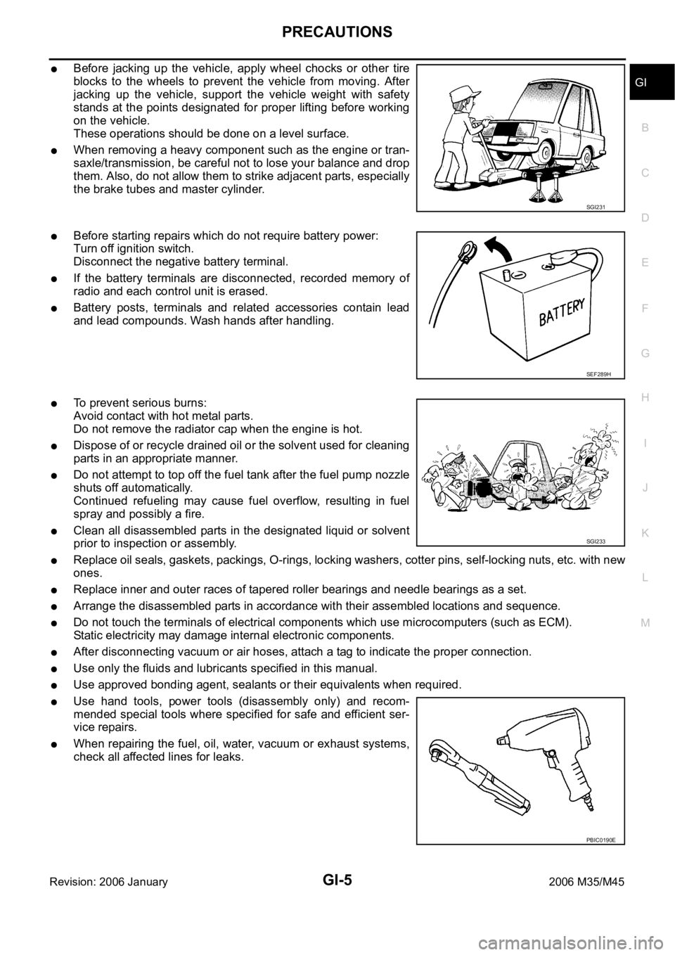
Before jacking up the vehicle, apply wheel chocks or other tire
blocks to the wheels to prevent the vehicle from moving. After
jacking up the vehicle, support the vehicle weight with safety
stands at the points designated for proper lifting before working
on the vehicle.
These operations should be done on a level surface.
When removing a heavy component such as the engine or tran-
saxle/transmission, be careful not to lose your balance and drop
them. Also, do not allow them to strike adjacent parts, especially
the brake tubes and master cylinder.
Before starting repairs which do not require battery power:
Turn off ignition switch.
Disconnect the negative battery terminal.
If the battery terminals are disconnected, recorded memory of
radio and each control unit is erased.
Battery posts, terminals and related accessories contain lead
and lead compounds. Wash hands after handling.
To prevent serious burns:
Avoid contact with hot metal parts.
Do not remove the radiator cap when the engine is hot.
Dispose of or recycle drained oil or the solvent used for cleaning
parts in an appropriate manner.
Do not attempt to top off the fuel tank after the fuel pump nozzle
shuts off automatically.
Continued refueling may cause fuel overflow, resulting in fuel
spray and possibly a fire.
Clean all disassembled parts in the designated liquid or solvent
prior to inspection or assembly.
Replace oil seals, gaskets, packings, O-rings, locking washers, cotter pins, self-locking nuts, etc. with new
ones.
Replace inner and outer races of tapered roller bearings and needle bearings as a set.
Arrange the disassembled parts in accordance with their assembled locations and sequence.
Do not touch the terminals of electrical components which use microcomputers (such as ECM).
Static electricity may damage internal electronic components.
After disconnecting vacuum or air hoses, attach a tag to indicate the proper connection.
Use only the fluids and lubricants specified in this manual.
Use approved bonding agent, sealants or their equivalents when required.
Use hand tools, power tools (disassembly only) and recom-
mended special tools where specified for safe and efficient ser-
vice repairs.
When repairing the fuel, oil, water, vacuum or exhaust systems,
check all affected lines for leaks.
SGI231
SEF289H
SGI233
PBIC0190E
Page 3484 of 5621

HOW TO USE THIS MANUAL
GI-21
C
D
E
F
G
H
I
J
K
L
MB
GI
Revision: 2006 January2006 M35/M45
Detectable Lines and Non-Detectable Lines
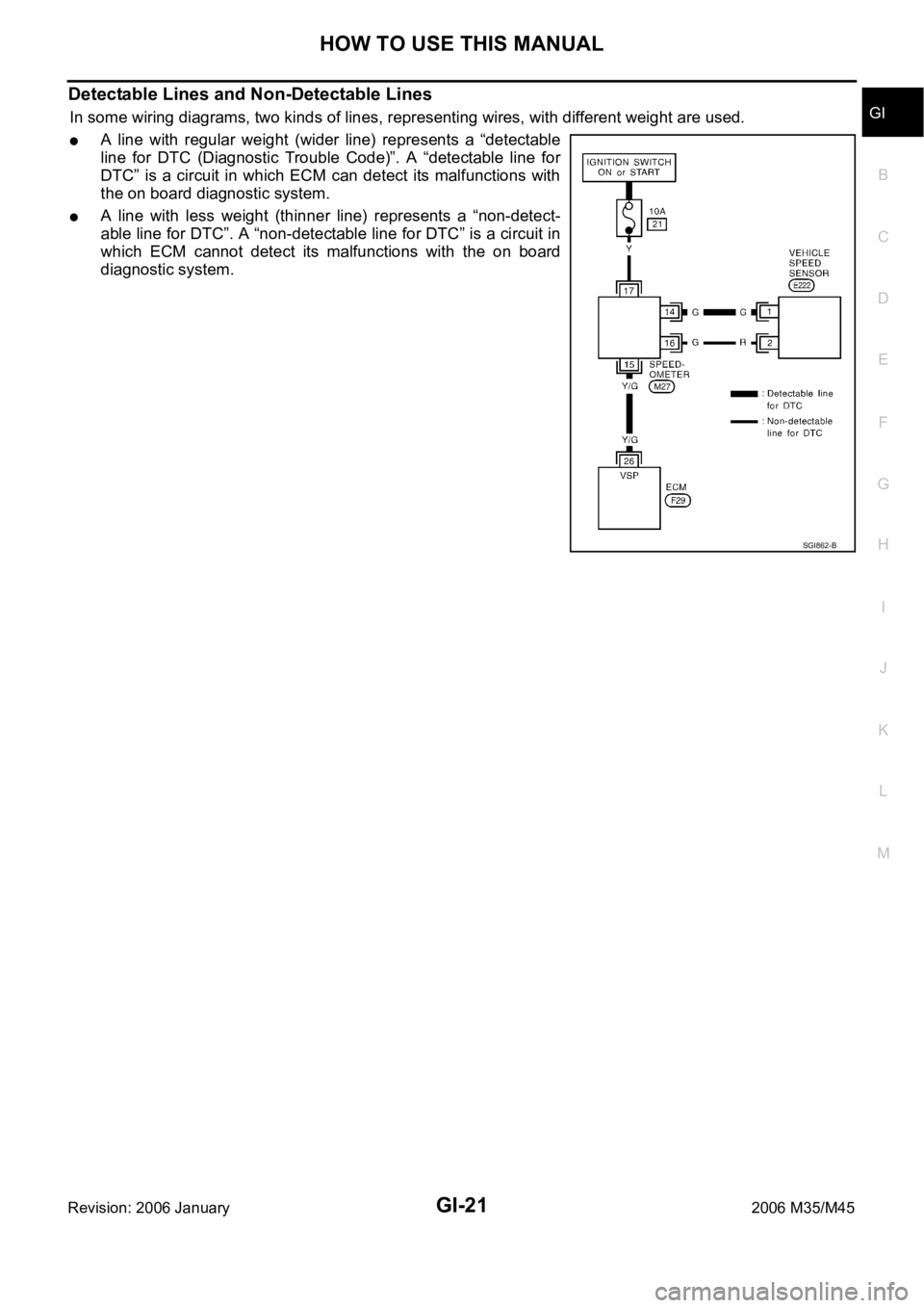
In some wiring diagrams, two kinds of lines, representing wires, with different weight are used.
A line with regular weight (wider line) represents a “detectable
line for DTC (Diagnostic Trouble Code)”. A “detectable line for
DTC” is a circuit in which ECM can detect its malfunctions with
the on board diagnostic system.
A line with less weight (thinner line) represents a “non-detect-
able line for DTC”. A “non-detectable line for DTC” is a circuit in
which ECM cannot detect its malfunctions with the on board
diagnostic system.
SGI862-B
Page 4465 of 5621

LT-38
HEADLAMP (FOR USA) - CONVENTIONAL TYPE -
Revision: 2006 January2006 M35/M45
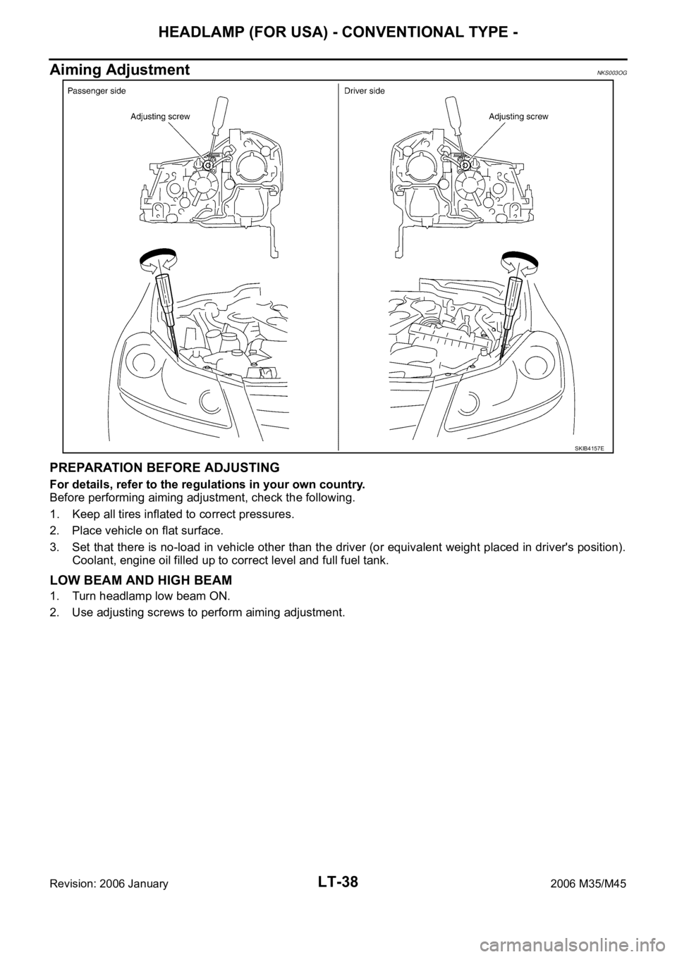
Aiming AdjustmentNKS003OG
PREPARATION BEFORE ADJUSTING
For details, refer to the regulations in your own country.
Before performing aiming adjustment, check the following.
1. Keep all tires inflated to correct pressures.
2. Place vehicle on flat surface.
3. Set that there is no-load in vehicle other than the driver (or equivalent weight placed in driver's position).
Coolant, engine oil filled up to correct level and full fuel tank.
LOW BEAM AND HIGH BEAM
1. Turn headlamp low beam ON.
2. Use adjusting screws to perform aiming adjustment.
SKIB4157E
Page 4501 of 5621

LT-74
HEADLAMP (FOR USA) - XENON TYPE -
Revision: 2006 January2006 M35/M45
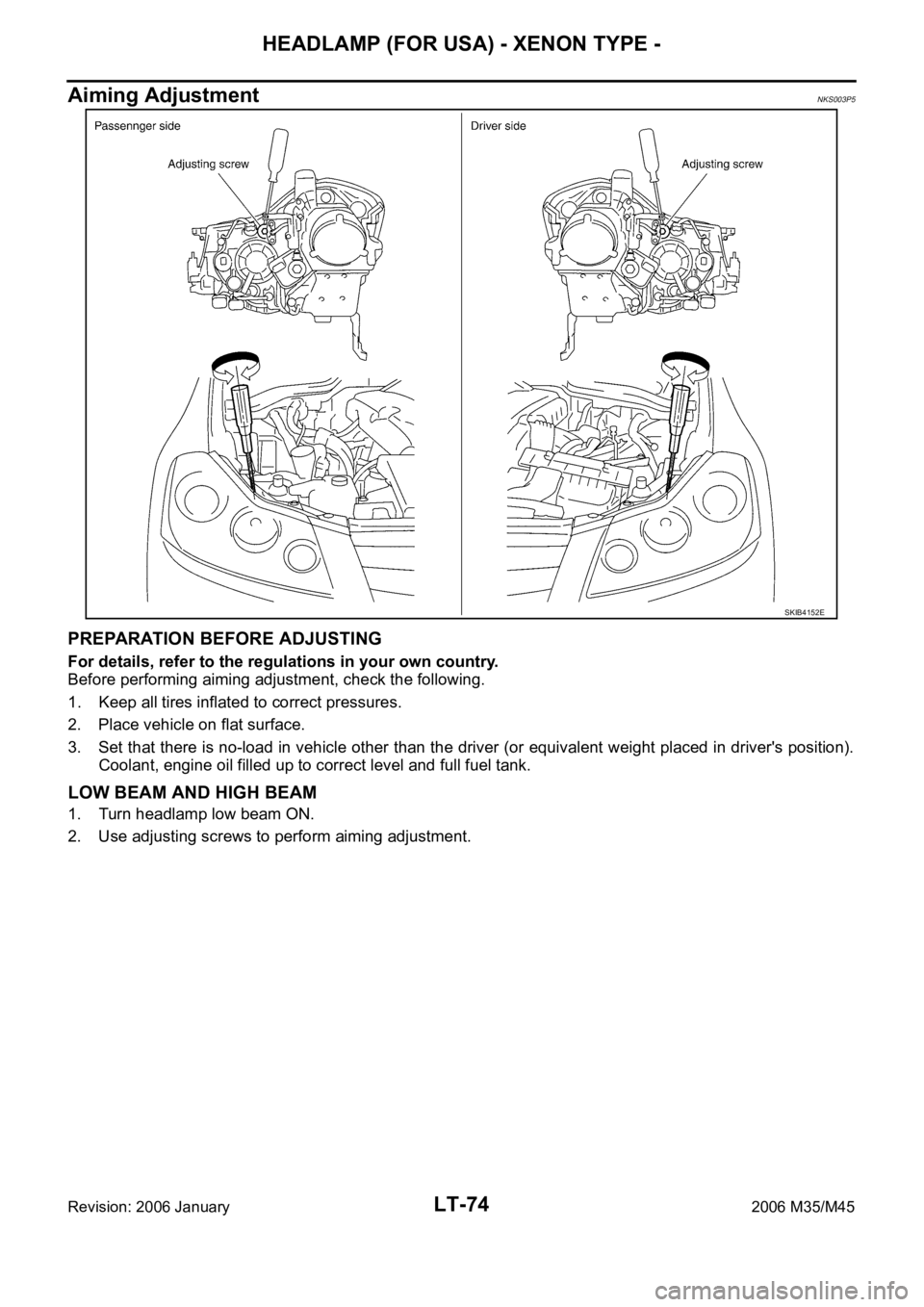
Aiming AdjustmentNKS003P5
PREPARATION BEFORE ADJUSTING
For details, refer to the regulations in your own country.
Before performing aiming adjustment, check the following.
1. Keep all tires inflated to correct pressures.
2. Place vehicle on flat surface.
3. Set that there is no-load in vehicle other than the driver (or equivalent weight placed in driver's position).
Coolant, engine oil filled up to correct level and full fuel tank.
LOW BEAM AND HIGH BEAM
1. Turn headlamp low beam ON.
2. Use adjusting screws to perform aiming adjustment.
SKIB4152E
Page 4563 of 5621

LT-136
ACTIVE AFS
Revision: 2006 January2006 M35/M45
HEADLAMP AUTO AIMING
Headlamp auto aiming control automatically corrects vertical deviation of light axis that is brought by the
change of vehicle height with changing number of passenger and laden weight, and relieves dazzle to oncom-
ing vehicles.
AFS control unit determines the current vehicle conditions by each received signals, and sends commands to
the low beam headlamps to auto aiming. With the headlamps (HIGH/LOW) illuminated and engine running,
the low beam headlamps are operative by AFS control unit commands.
The height sensor is located on the left side of the rear suspension member and detects rear vehicle height
change by sensing the displacement of the rear suspension arm. And transmits a height sensor signal to the
AFS control unit.
With reference to the rear vehicle height under the empty condition, light axis of low beam with low rear vehi-
cle height is relatively higher than that with the empty condition. AFS control unit switches drive signal corrects
height of low beam axis to maintain height of light axis with empty condition.
Light axis of low beam with high rear vehicle height is relatively lower than that with empty condition. Light axis
of low beam with empty condition is set as upper limit of headlamp auto aiming control operation. Control to
correct deviation is not performed when light axis of low beam gets relatively higher than that with empty con-
dition. Timing of control is switched in accordance with driving conditions.
Headlamp auto aiming operation
*1: Included high beam illuminated
*2: Control timing of drive signal is switched by vehicle speed and accelerating/decelerating vehicle.
*3: Control is performed without regard to the condition of AFS switch. Headlamp auto aiming control function cannot be cancelled.
OUTLINE
Power is supplied
When the ignition switch is ON or START position, power is supplied
through 10A fuse [No.12, located in fuse block (J/B)]
to AFS control unit terminal 1
to front combination lamp LH and RH terminal 13
to AFS switch terminal 1.
Ground is supplied
to AFS control unit terminal 25
through grounds M16 and M70,
to front combination lamp LH and RH terminal 11
through grounds E22 and E43.
SKIB4707E
Operating range With 18-inch wheel (Reference value) With 19-inch wheel (Reference value) Vehicle height
A 0 mm (Standard position) 0 mm (Standard position) Unloaded vehicle position
B Approx. 200 mm (7.9 in) Approx.180 mm (7.1 in) Low
Low beam status Vehicle speed Engine speed AFS switch
Illuminated*
1Control switch by driving conditions*2While engine running
Irrespective*3