2006 INFINITI M35 bulb
[x] Cancel search: bulbPage 4532 of 5621
HEADLAMP (FOR CANADA) - DAYTIME LIGHT SYSTEM -
LT-105
C
D
E
F
G
H
I
J
L
MA
B
LT
Revision: 2006 January2006 M35/M45
8. CHECK CIRCUIT BETWEEN IPDM E/R AND FRONT COMBINATION LAMP
1. Turn ignition switch OFF.
2. Disconnect IPDM E/R connector.
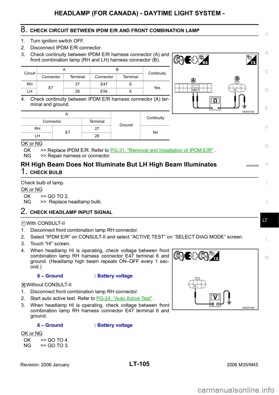
3. Check continuity between IPDM E/R harness connector (A) and
front combination lamp (RH and LH) harness connector (B).
4. Check continuity between IPDM E/R harness connector (A) ter-
minal and ground.
OK or NG
OK >> Replace IPDM E/R. Refer to PG-31, "Removal and Installation of IPDM E/R" .
NG >> Repair harness or connector.
RH High Beam Does Not Illuminate But LH High Beam IlluminatesNKS003PM
1. CHECK BULB
Check bulb of lamp.
OK or NG
OK >> GO TO 2.
NG >> Replace headlamp bulb.
2. CHECK HEADLAMP INPUT SIGNAL
With CONSULT-II
1. Disconnect front combination lamp RH connector.
2. Select “IPDM E/R” on CONSULT-II and select “ACTIVE TEST” on “SELECT DIAG MODE” screen.
3. Touch “HI” screen.
4. When headlamp HI is operating, check voltage between front
combination lamp RH harness connector E47 terminal 6 and
ground. (Headlamp high beam repeats ON–OFF every 1 sec-
ond.)
Without CONSULT-II
1. Disconnect front combination lamp RH connector.
2. Start auto active test. Refer to PG-24, "
Auto Active Test" .
3. When headlamp HI is operating, check voltage between front
combination lamp RH harness connector E47 terminal 6 and
ground.
OK or NG
OK >> GO TO 4.
NG >> GO TO 3.
CircuitAB
Continuity
Connector Terminal Connector Terminal
RH
E727 E47 6
Ye s
LH 28 E54 6
A
GroundContinuity
Connector Terminal
RH
E727
No
LH 28
SKIB4753E
6 – Ground : Battery voltage
6 – Ground : Battery voltage
SKIB4749E
Page 4534 of 5621
HEADLAMP (FOR CANADA) - DAYTIME LIGHT SYSTEM -
LT-107
C
D
E
F
G
H
I
J
L
MA
B
LT
Revision: 2006 January2006 M35/M45
6. CHECK DAYTIME RELAY
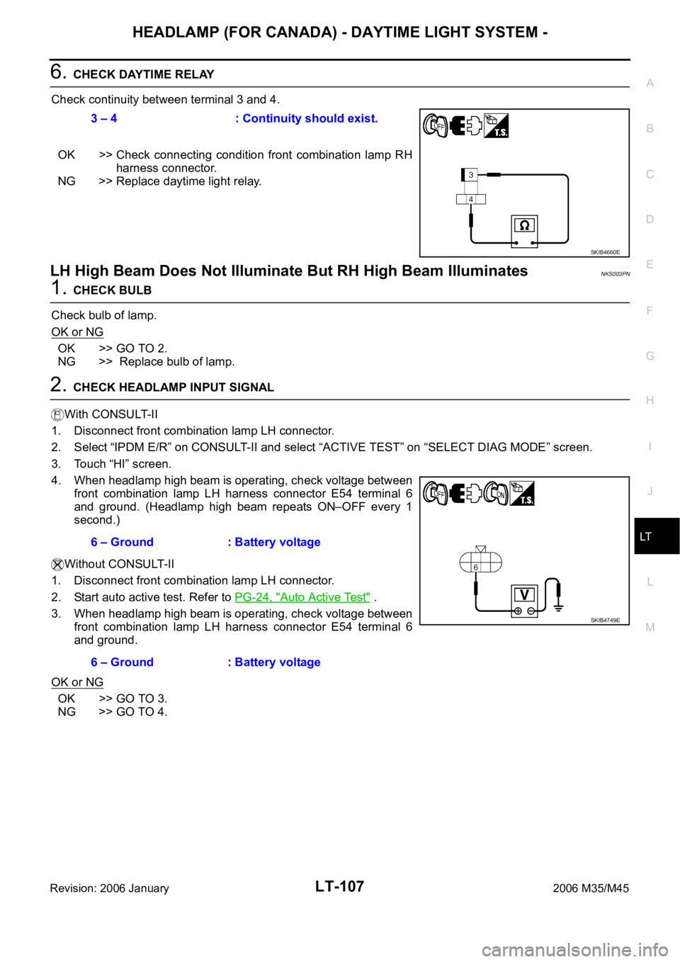
Check continuity between terminal 3 and 4.
OK >> Check connecting condition front combination lamp RH
harness connector.
NG >> Replace daytime light relay.
LH High Beam Does Not Illuminate But RH High Beam IlluminatesNKS003PN
1. CHECK BULB
Check bulb of lamp.
OK or NG
OK >> GO TO 2.
NG >> Replace bulb of lamp.
2. CHECK HEADLAMP INPUT SIGNAL
With CONSULT-II
1. Disconnect front combination lamp LH connector.
2. Select “IPDM E/R” on CONSULT-II and select “ACTIVE TEST” on “SELECT DIAG MODE” screen.
3. Touch “HI” screen.
4. When headlamp high beam is operating, check voltage between
front combination lamp LH harness connector E54 terminal 6
and ground. (Headlamp high beam repeats ON–OFF every 1
second.)
Without CONSULT-II
1. Disconnect front combination lamp LH connector.
2. Start auto active test. Refer to PG-24, "
Auto Active Test" .
3. When headlamp high beam is operating, check voltage between
front combination lamp LH harness connector E54 terminal 6
and ground.
OK or NG
OK >> GO TO 3.
NG >> GO TO 4.3 – 4 : Continuity should exist.
SKIB4660E
6 – Ground : Battery voltage
6 – Ground : Battery voltage
SKIB4749E
Page 4537 of 5621
LT-110
HEADLAMP (FOR CANADA) - DAYTIME LIGHT SYSTEM -
Revision: 2006 January2006 M35/M45
4. CHECK HEADLAMP INPUT SIGNAL
With CONSULT-II
1. Turn ignition switch OFF.
2. Disconnect front combination lamp RH and LH connector.
3. Select “IPDM E/R” on CONSULT-II. Select “ACTIVE TEST” on “SELECT DIAG MODE” screen.
4. Select “LAMPS” on “SELECT TEST ITEM” screen.
5. Touch “LO” screen.
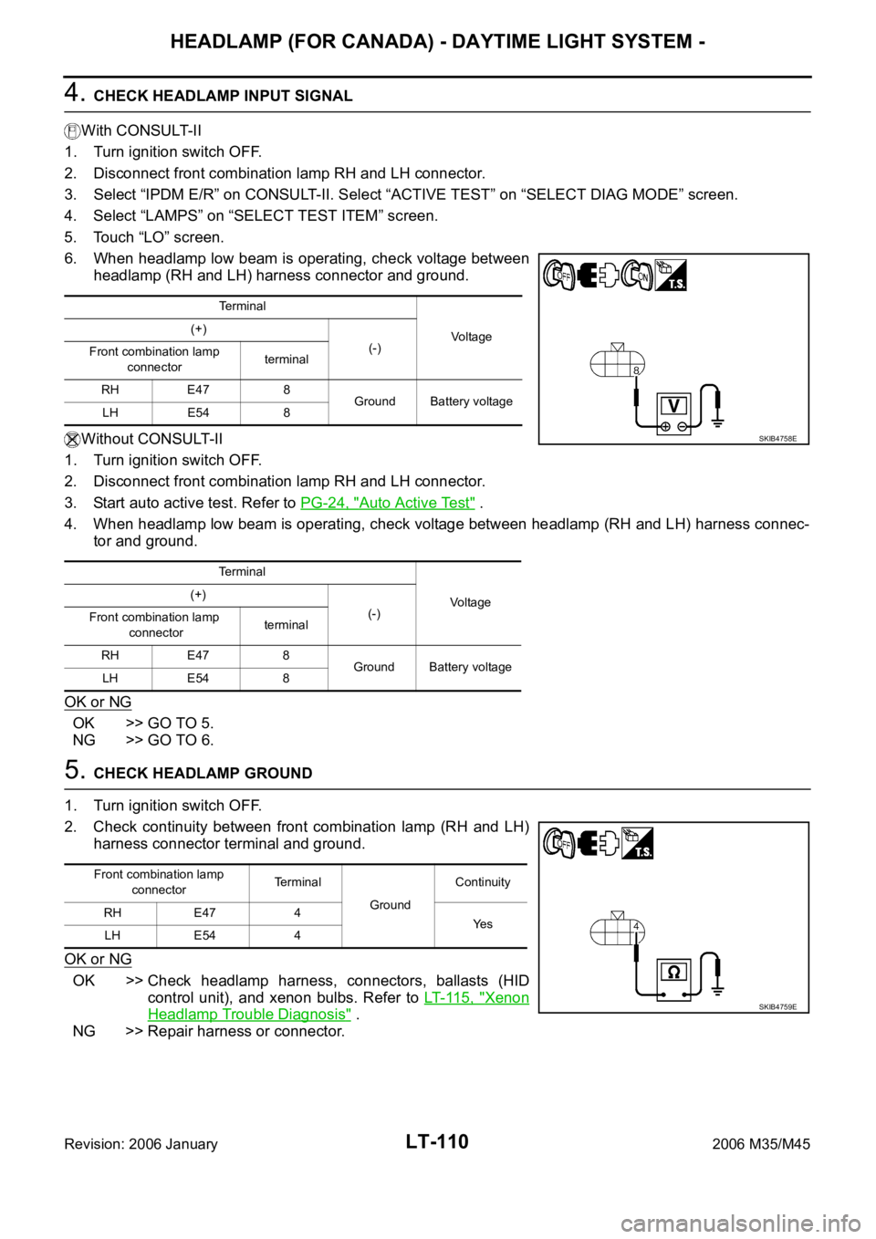
6. When headlamp low beam is operating, check voltage between
headlamp (RH and LH) harness connector and ground.
Without CONSULT-II
1. Turn ignition switch OFF.
2. Disconnect front combination lamp RH and LH connector.
3. Start auto active test. Refer to PG-24, "
Auto Active Test" .
4. When headlamp low beam is operating, check voltage between headlamp (RH and LH) harness connec-
tor and ground.
OK or NG
OK >> GO TO 5.
NG >> GO TO 6.
5. CHECK HEADLAMP GROUND
1. Turn ignition switch OFF.
2. Check continuity between front combination lamp (RH and LH)
harness connector terminal and ground.
OK or NG
OK >> Check headlamp harness, connectors, ballasts (HID
control unit), and xenon bulbs. Refer to LT- 11 5 , "
Xenon
Headlamp Trouble Diagnosis" .
NG >> Repair harness or connector.
Terminal
Vo l ta g e (+)
(-)
Front combination lamp
connectorterminal
RH E47 8
Ground Battery voltage
LH E54 8
Terminal
Voltage (+)
(-)
Front combination lamp
connectorterminal
RH E47 8
Ground Battery voltage
LH E54 8
SKIB4758E
Front combination lamp
connectorTerminal
GroundContinuity
RH E47 4
Ye s
LH E54 4
SKIB4759E
Page 4539 of 5621
LT-112
HEADLAMP (FOR CANADA) - DAYTIME LIGHT SYSTEM -
Revision: 2006 January2006 M35/M45
Headlamp Low Beam Does Not Illuminate (One Side)NKS003PP
1. CHECK BULB
Check ballast (HID control unit) and xenon bulb of lamp which does not illuminate. Refer to LT- 11 5 , "
Xenon
Headlamp Trouble Diagnosis" .
OK or NG
OK >> GO TO 2.
NG >> Repair malfunctioning part.
2. CHECK HEADLAMP INPUT SIGNAL
With CONSULT-II
1. Turn ignition switch OFF.
2. Disconnect front combination lamp RH or LH connector.
3. Select “IPDM E/R” on CONSULT-II. Select “ACTIVE TEST” on “SELECT DIAG MODE” screen.
4. Select “LAMPS” on “SELECT TEST ITEM” screen.
5. Touch “LO” screen.
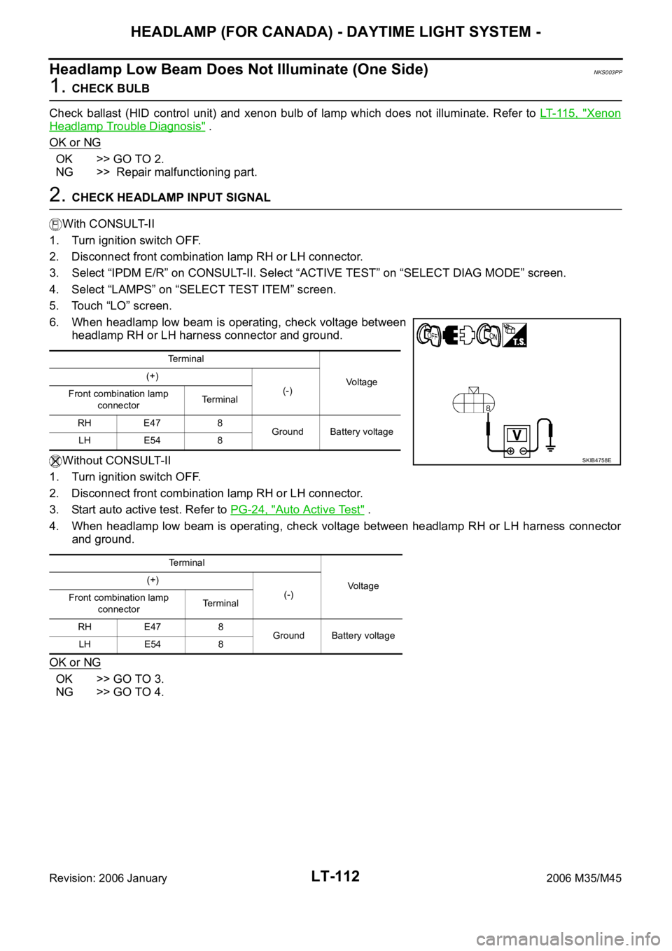
6. When headlamp low beam is operating, check voltage between
headlamp RH or LH harness connector and ground.
Without CONSULT-II
1. Turn ignition switch OFF.
2. Disconnect front combination lamp RH or LH connector.
3. Start auto active test. Refer to PG-24, "
Auto Active Test" .
4. When headlamp low beam is operating, check voltage between headlamp RH or LH harness connector
and ground.
OK or NG
OK >> GO TO 3.
NG >> GO TO 4.
Terminal
Vo l ta g e (+)
(-)
Front combination lamp
connectorTerminal
RH E47 8
Ground Battery voltage
LH E54 8
Terminal
Voltage (+)
(-)
Front combination lamp
connectorTerminal
RH E47 8
Ground Battery voltage
LH E54 8
SKIB4758E
Page 4542 of 5621

HEADLAMP (FOR CANADA) - DAYTIME LIGHT SYSTEM -
LT-115
C
D
E
F
G
H
I
J
L
MA
B
LT
Revision: 2006 January2006 M35/M45
General Information for Xenon Headlamp Trouble DiagnosisNKS003PR
In most cases, malfunction of xenon headlamp - "does not illuminate", "flickers" or "dark" - is caused by a mal-
functioning xenon bulb. A HID control unit or lamp housing, however, may be a cause of malfunction. Be sure
to perform trouble diagnosis following the steps described below.
CAUTION:NKS003PS
Installation or removal of connector must be done with lighting switch OFF.
When lamp is illuminated (when lighting switch is ON), do not touch harness, HID control unit, inside of
lamp, or lamp metal parts.
To check illumination, temporarily install lamp in the vehicle. Be sure to connect power at the vehicle-side
connector.
If the error can be traced directly to the electrical system, first check for items such as burned-out fuses
and fusible links, broken wires or loose connectors, pulled-out terminals, and improper connections.
Do not work with wet hands.
Using a tester for HID control unit circuit trouble diagnosis is prohibited.
Disassembling the HID control unit or harnesses (bulb socket harness, ECM harness) is prohibited.
Immediately after illumination, the light intensity and color will fluctuate, but there is nothing wrong.
When the bulb has reached the end of its lifetime, the brightness may drop significantly, it may flash
repeatedly, or the light may turn a reddish color.
Xenon Headlamp Trouble DiagnosisNKS003PT
1. CHECK 1: XENON HEADLAMP LIGHTING
Install normal xenon bulb to corresponding xenon bulb headlamp, and check if lamp lights up.
OK or NG
OK >> Replace xenon bulb.
NG >> GO TO 2.
2. CHECK 2: XENON HEADLAMP LIGHTING
Install normal HID control unit to corresponding xenon headlamp, and check if lamp lights up.
OK or NG
OK >> Replace HID control unit.
NG >> GO TO 3.
3. CHECK 3: XENON HEADLAMP LIGHTING
Install normal xenon lamp housing assembly to corresponding xenon headlamp, and check if lamp lights up.
OK or NG
OK >> Replace xenon headlamp housing assembly. [Malfunction in starter (boosting circuit) in xenon
headlamp housing]
NG >> INSPECTION END
Aiming AdjustmentNKS003PU
Refer to LT- 7 4 , "Aiming Adjustment" .
Bulb ReplacementNKS003PV
Refer to LT- 7 5 , "Bulb Replacement" .
Removal and InstallationNKS003PW
Refer to LT- 4 1 , "Removal and Installation" .
Disassembly and AssemblyNKS003PX
Refer to LT- 7 7 , "Disassembly and Assembly" .
Page 4565 of 5621
LT-138
ACTIVE AFS
Revision: 2006 January2006 M35/M45
through front combination lamp RH terminal 21.
Swivel position sensor detects swivel angle during ignition switch ON, and transmits swivel position sensor
signals to the AFS control unit:
When ignition switch is turn to ON position, power is supplied
to front combination lamp RH terminal 15
through AFS control unit terminal 4.
When ignition switch is turn to ON position, swivel position sensor input signal is supplied
to AFS control unit terminal 9
through front combination lamp RH terminal 14.
Ground is supplied
to front combination lamp RH terminal 19
through AFS control unit terminal 2.
The low beam headlamp RH starts to swivel to the right.
The swivel motor driving signals are blocked and the swivel motion stops when the steering angle reaches
approximately more than 80 degrees (predetermined). The low beam headlamp will not swivel any further no
matter how further right. As the steering wheel is turned back to the left, the swivel motor driving signals (both
1-phase and 2-phase) will be reversed, causing low beam headlamp RH to start swiveling to the left. When
steering angle becomes smaller than predetermined value, the low beam headlamp is set in the straight-
ahead position, swivel motor driving signals are blocked and low beam headlamps stop swiveling.
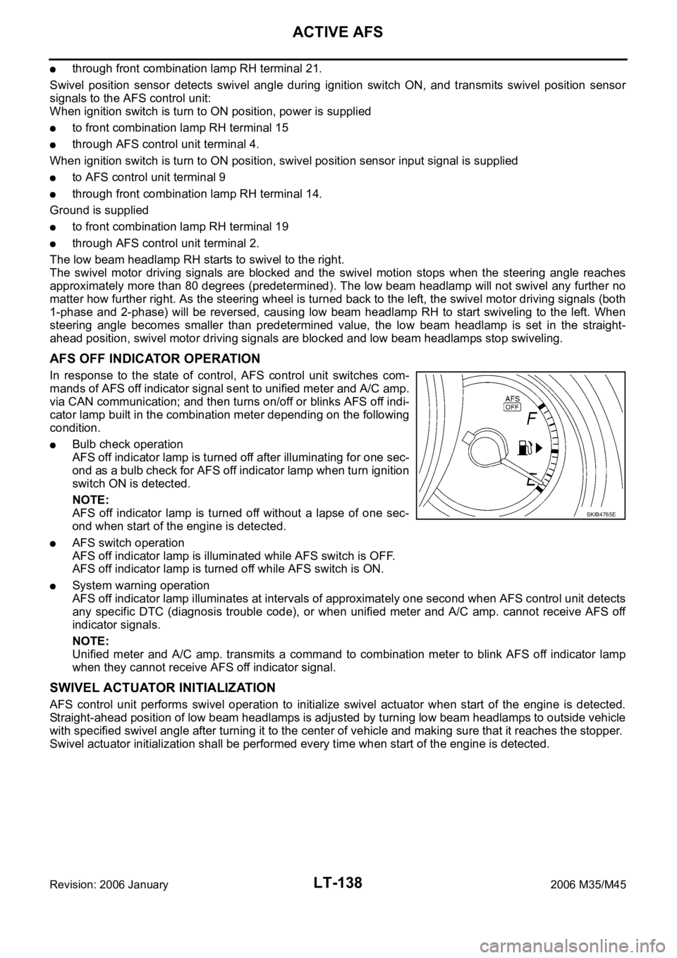
AFS OFF INDICATOR OPERATION
In response to the state of control, AFS control unit switches com-
mands of AFS off indicator signal sent to unified meter and A/C amp.
via CAN communication; and then turns on/off or blinks AFS off indi-
cator lamp built in the combination meter depending on the following
condition.
Bulb check operation
AFS off indicator lamp is turned off after illuminating for one sec-
ond as a bulb check for AFS off indicator lamp when turn ignition
switch ON is detected.
NOTE:
AFS off indicator lamp is turned off without a lapse of one sec-
ond when start of the engine is detected.
AFS switch operation
AFS off indicator lamp is illuminated while AFS switch is OFF.
AFS off indicator lamp is turned off while AFS switch is ON.
System warning operation
AFS off indicator lamp illuminates at intervals of approximately one second when AFS control unit detects
any specific DTC (diagnosis trouble code), or when unified meter and A/C amp. cannot receive AFS off
indicator signals.
NOTE:
Unified meter and A/C amp. transmits a command to combination meter to blink AFS off indicator lamp
when they cannot receive AFS off indicator signal.
SWIVEL ACTUATOR INITIALIZATION
AFS control unit performs swivel operation to initialize swivel actuator when start of the engine is detected.
Straight-ahead position of low beam headlamps is adjusted by turning low beam headlamps to outside vehicle
with specified swivel angle after turning it to the center of vehicle and making sure that it reaches the stopper.
Swivel actuator initialization shall be performed every time when start of the engine is detected.
SKIB4765E
Page 4632 of 5621
FRONT FOG LAMP
LT-205
C
D
E
F
G
H
I
J
L
MA
B
LT
Revision: 2006 January2006 M35/M45
4. CHECK FOG LAMP INPUT SIGNAL
With CONSULT-II
1. Turn ignition switch OFF.
2. Disconnect front fog lamp RH and LH connector.
3. Select “IPDM E/R” on CONSULT-II. Select “ACTIVE TEST” on “SELECT DIAG MODE” screen.
4. Select “LAMPS” on “SELECT TEST ITEM” screen.
5. Touch “FOG” screen.
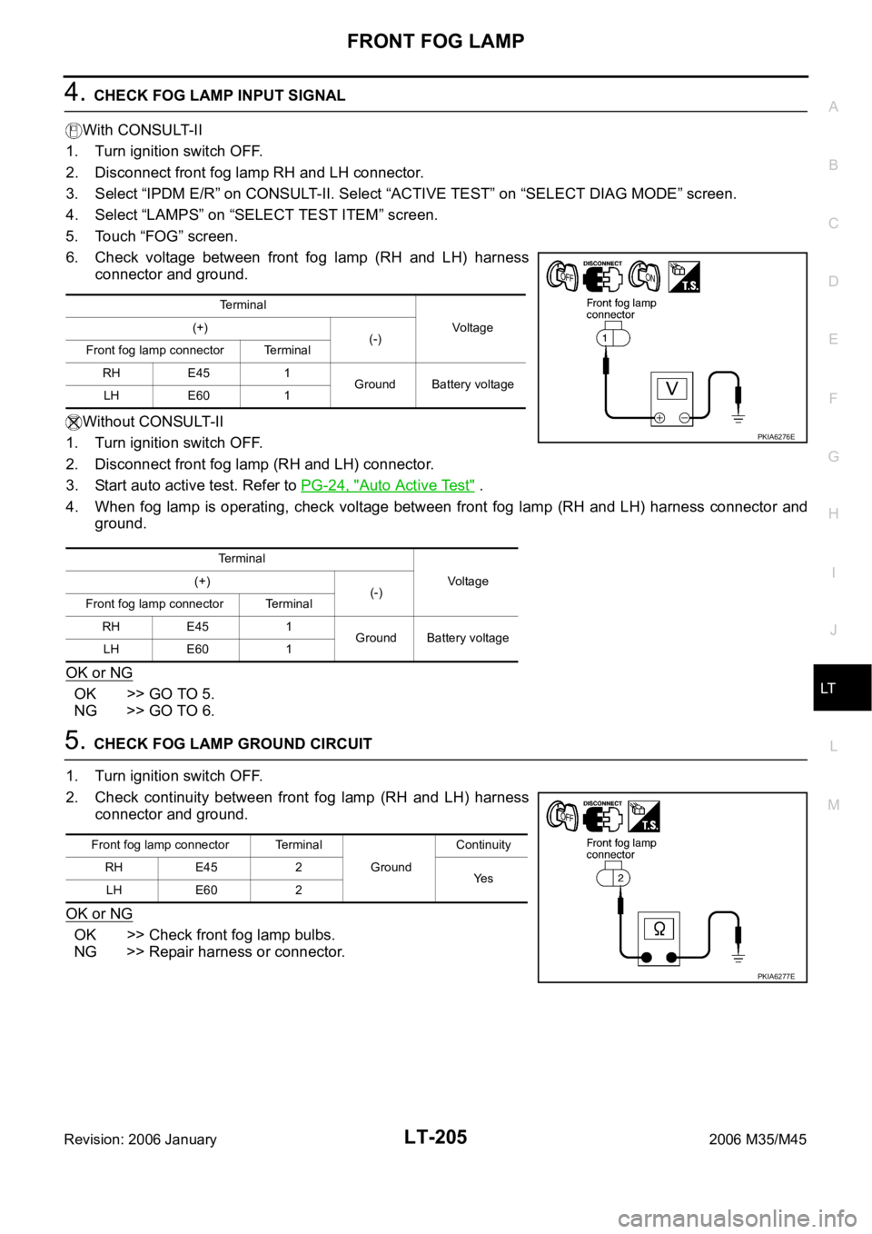
6. Check voltage between front fog lamp (RH and LH) harness
connector and ground.
Without CONSULT-II
1. Turn ignition switch OFF.
2. Disconnect front fog lamp (RH and LH) connector.
3. Start auto active test. Refer to PG-24, "
Auto Active Test" .
4. When fog lamp is operating, check voltage between front fog lamp (RH and LH) harness connector and
ground.
OK or NG
OK >> GO TO 5.
NG >> GO TO 6.
5. CHECK FOG LAMP GROUND CIRCUIT
1. Turn ignition switch OFF.
2. Check continuity between front fog lamp (RH and LH) harness
connector and ground.
OK or NG
OK >> Check front fog lamp bulbs.
NG >> Repair harness or connector.
Te r m i n a l
Voltage (+)
(-)
Front fog lamp connector Terminal
RH E45 1
Ground Battery voltage
LH E60 1
Te r m i n a l
Voltag e (+)
(-)
Front fog lamp connector Terminal
RH E45 1
Ground Battery voltage
LH E60 1
PKIA6276E
Front fog lamp connector Terminal
GroundContinuity
RH E45 2
Ye s
LH E60 2
PKIA6277E
Page 4634 of 5621
FRONT FOG LAMP
LT-207
C
D
E
F
G
H
I
J
L
MA
B
LT
Revision: 2006 January2006 M35/M45
Front Fog Lamp Does Not Illuminate (One Side)NKS003RF
1. CHECK BULB
Check bulb of fog lamp which does not illuminate.
OK or NG
OK >> GO TO 2.
NG >> Replace front fog lamp bulb.
2. CHECK FOG LAMP INPUT SIGNAL
1. Turn ignition switch OFF.
2. Disconnect front fog lamp RH or LH connector.
3. Turn ignition switch ON.
4. Fog lamp switch is turned ON position.
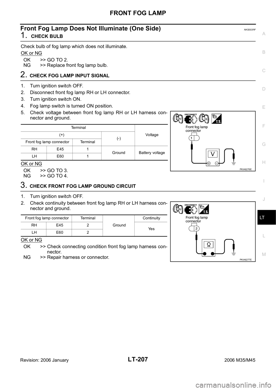
5. Check voltage between front fog lamp RH or LH harness con-
nector and ground.
OK or NG
OK >> GO TO 3.
NG >> GO TO 4.
3. CHECK FRONT FOG LAMP GROUND CIRCUIT
1. Turn ignition switch OFF.
2. Check continuity between front fog lamp RH or LH harness con-
nector and ground.
OK or NG
OK >> Check connecting condition front fog lamp harness con-
nector.
NG >> Repair harness or connector.
Terminal
Voltag e (+)
(-)
Front fog lamp connector Terminal
RH E45 1
Ground Battery voltage
LH E60 1
PKIA6276E
Front fog lamp connector Terminal
Ground Continuity
RH E45 2
Ye s
LH E60 2
PKIA6277E