Page 1039 of 5621
BL-100
INTELLIGENT KEY SYSTEM
Revision: 2006 January2006 M35/M45
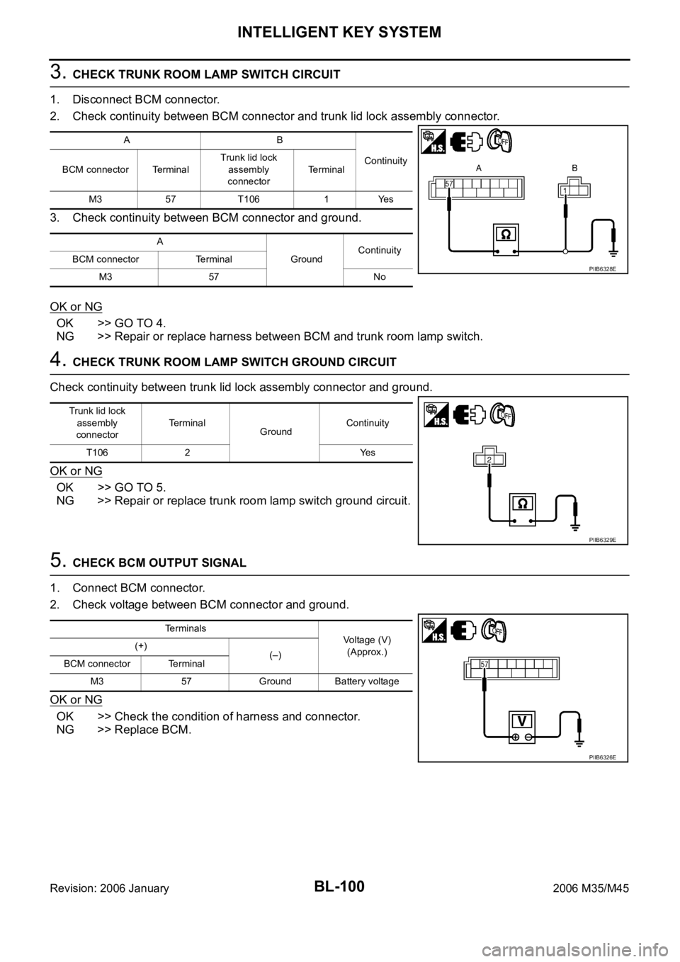
3. CHECK TRUNK ROOM LAMP SWITCH CIRCUIT
1. Disconnect BCM connector.
2. Check continuity between BCM connector and trunk lid lock assembly connector.
3. Check continuity between BCM connector and ground.
OK or NG
OK >> GO TO 4.
NG >> Repair or replace harness between BCM and trunk room lamp switch.
4. CHECK TRUNK ROOM LAMP SWITCH GROUND CIRCUIT
Check continuity between trunk lid lock assembly connector and ground.
OK or NG
OK >> GO TO 5.
NG >> Repair or replace trunk room lamp switch ground circuit.
5. CHECK BCM OUTPUT SIGNAL
1. Connect BCM connector.
2. Check voltage between BCM connector and ground.
OK or NG
OK >> Check the condition of harness and connector.
NG >> Replace BCM.
AB
Continuity
BCM connector TerminalTrunk lid lock
assembly
connectorTerminal
M3 57 T106 1 Yes
A
GroundContinuity
BCM connector Terminal
M3 57 No
PIIB6328E
Trunk lid lock
assembly
connectorTerminal
GroundContinuity
T106 2 Yes
PIIB6329E
Terminals
Voltage (V)
(Approx.) (+)
(–)
BCM connector Terminal
M3 57 Ground Battery voltage
PIIB6326E
Page 1040 of 5621
INTELLIGENT KEY SYSTEM
BL-101
C
D
E
F
G
H
J
K
L
MA
B
BL
Revision: 2006 January2006 M35/M45
Check Door Request SwitchNIS001XQ
1. CHECK DOOR REQUEST SWITCH
With CONSULT-II
Check door request switch (“DR REQ SW” or “AS REQ SW”) in “DATA MONITOR” mode.
Without CONSULT-II
1. Turn ignition switch OFF.
2. Check voltage between Intelligent Key unit harness connector and ground.
OK or NG
OK >> Door request switch is OK.
NG >> GO TO 2.
Monitor item Condition
DR REQ SW
AS REQ SWDoor request switch is pressed : ON
Door request switch is released : OFF
PIIB4260E
Te r m i n a l s
Door
request
switch
ConditionVoltage (V)
(Approx.) (+)
(–)
Intelligent Key unit
connectorTerminal
M32Door request
switch
(driver side)2
GroundPressed 0
Released 5
Door request
switch
(passenger side)22Pressed 0
Released 5
PIIB6330E
Page 1041 of 5621
BL-102
INTELLIGENT KEY SYSTEM
Revision: 2006 January2006 M35/M45
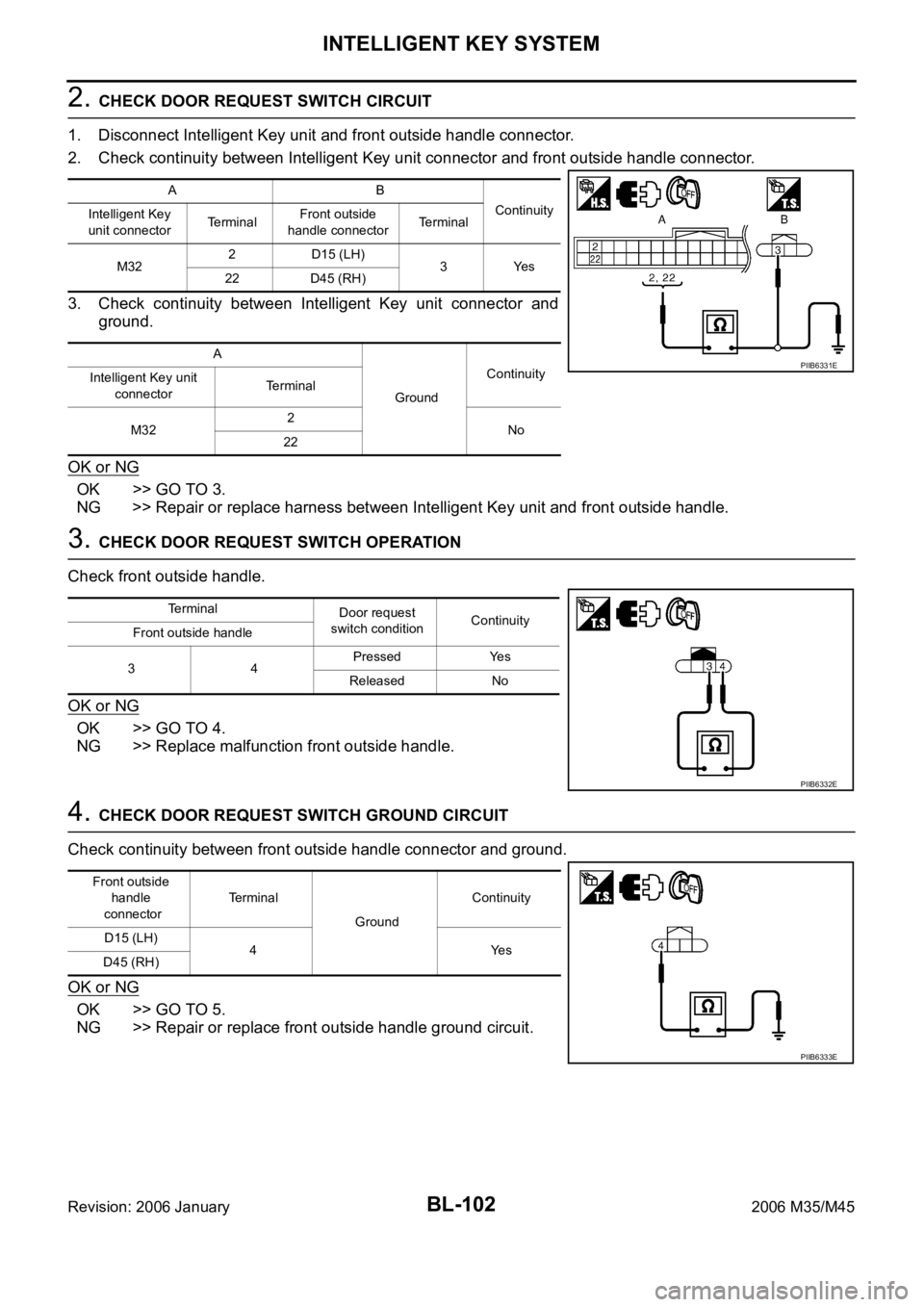
2. CHECK DOOR REQUEST SWITCH CIRCUIT
1. Disconnect Intelligent Key unit and front outside handle connector.
2. Check continuity between Intelligent Key unit connector and front outside handle connector.
3. Check continuity between Intelligent Key unit connector and
ground.
OK or NG
OK >> GO TO 3.
NG >> Repair or replace harness between Intelligent Key unit and front outside handle.
3. CHECK DOOR REQUEST SWITCH OPERATION
Check front outside handle.
OK or NG
OK >> GO TO 4.
NG >> Replace malfunction front outside handle.
4. CHECK DOOR REQUEST SWITCH GROUND CIRCUIT
Check continuity between front outside handle connector and ground.
OK or NG
OK >> GO TO 5.
NG >> Repair or replace front outside handle ground circuit.
AB
Continuity
Intelligent Key
unit connectorTe r m i n a lFront outside
handle connectorTerminal
M322 D15 (LH)
3Yes
22 D45 (RH)
A
GroundContinuity
Intelligent Key unit
connectorTerminal
M322
No
22
PIIB6331E
Terminal
Door request
switch conditionContinuity
Front outside handle
34Pressed Yes
Released No
PIIB6332E
Front outside
handle
connectorTe r m i n a l
GroundContinuity
D15 (LH)
4Yes
D45 (RH)
PIIB6333E
Page 1042 of 5621
INTELLIGENT KEY SYSTEM
BL-103
C
D
E
F
G
H
J
K
L
MA
B
BL
Revision: 2006 January2006 M35/M45
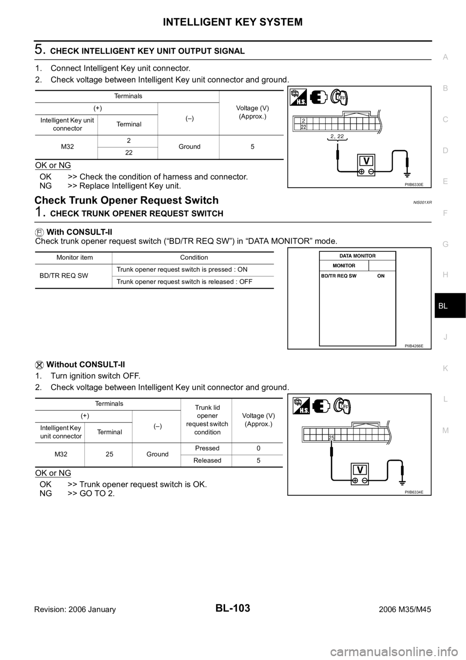
5. CHECK INTELLIGENT KEY UNIT OUTPUT SIGNAL
1. Connect Intelligent Key unit connector.
2. Check voltage between Intelligent Key unit connector and ground.
OK or NG
OK >> Check the condition of harness and connector.
NG >> Replace Intelligent Key unit.
Check Trunk Opener Request SwitchNIS001XR
1. CHECK TRUNK OPENER REQUEST SWITCH
With CONSULT-II
Check trunk opener request switch (“BD/TR REQ SW”) in “DATA MONITOR” mode.
Without CONSULT-II
1. Turn ignition switch OFF.
2. Check voltage between Intelligent Key unit connector and ground.
OK or NG
OK >> Trunk opener request switch is OK.
NG >> GO TO 2.
Terminals
Voltage (V)
(Approx.) (+)
(–)
Intelligent Key unit
connectorTerminal
M322
Ground 5
22
PIIB6330E
Monitor item Condition
BD/TR REQ SWTrunk opener request switch is pressed : ON
Trunk opener request switch is released : OFF
PIIB4266E
Terminals
Trunk lid
opener
request switch
conditionVoltage (V)
(Approx.) (+)
(–)
Intelligent Key
unit connectorTerminal
M32 25 GroundPressed 0
Released 5
PIIB6334E
Page 1043 of 5621
BL-104
INTELLIGENT KEY SYSTEM
Revision: 2006 January2006 M35/M45
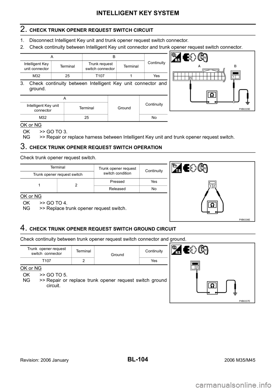
2. CHECK TRUNK OPENER REQUEST SWITCH CIRCUIT
1. Disconnect Intelligent Key unit and trunk opener request switch connector.
2. Check continuity between Intelligent Key unit connector and trunk opener request switch connector.
3. Check continuity between Intelligent Key unit connector and
ground.
OK or NG
OK >> GO TO 3.
NG >> Repair or replace harness between Intelligent Key unit and trunk opener request switch.
3. CHECK TRUNK OPENER REQUEST SWITCH OPERATION
Check trunk opener request switch.
OK or NG
OK >> GO TO 4.
NG >> Replace trunk opener request switch.
4. CHECK TRUNK OPENER REQUEST SWITCH GROUND CIRCUIT
Check continuity between trunk opener request switch connector and ground.
OK or NG
OK >> GO TO 5.
NG >> Repair or replace trunk opener request switch ground
circuit.
AB
Continuity
Intelligent Key
unit connectorTerminal Trunk request
switch connectorTerminal
M32 25 T107 1 Yes
A
GroundContinuity
Intelligent Key unit
connectorTe r m i n a l
M32 25 No
PIIB6335E
Terminal
Trunk opener request
switch conditionContinuity
Trunk opener request switch
12Pressed Yes
Released No
PIIB6336E
Trunk opener request
switch connectorTerminal
GroundContinuity
T107 2 Yes
PIIB6337E
Page 1044 of 5621
INTELLIGENT KEY SYSTEM
BL-105
C
D
E
F
G
H
J
K
L
MA
B
BL
Revision: 2006 January2006 M35/M45
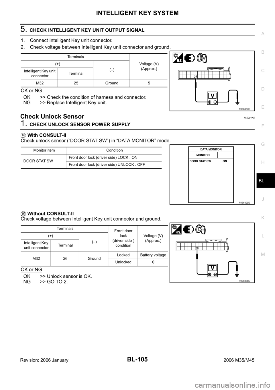
5. CHECK INTELLIGENT KEY UNIT OUTPUT SIGNAL
1. Connect Intelligent Key unit connector.
2. Check voltage between Intelligent Key unit connector and ground.
OK or NG
OK >> Check the condition of harness and connector.
NG >> Replace Intelligent Key unit.
Check Unlock SensorNIS001XS
1. CHECK UNLOCK SENSOR POWER SUPPLY
With CONSULT-II
Check unlock sensor (“DOOR STAT SW”) in “DATA MONITOR” mode.
Without CONSULT-II
Check voltage between Intelligent Key unit connector and ground.
OK or NG
OK >> Unlock sensor is OK.
NG >> GO TO 2.
Terminals
Voltage (V)
(Approx.) (+)
(–)
Intelligent Key unit
connectorTerminal
M32 25 Ground 5
PIIB6334E
Monitor item Condition
DOOR STAT SWFront door lock (driver side) LOCK : ON
Front door lock (driver side) UNLOCK : OFF
PIIB6399E
Terminals
Front door
lock
(driver side )
conditionVoltage (V)
(Approx.) (+)
(–)
Intelligent Key
unit connectorTerminal
M32 26 GroundLocked Battery voltage
Unlocked 0
PIIB6338E
Page 1045 of 5621
BL-106
INTELLIGENT KEY SYSTEM
Revision: 2006 January2006 M35/M45
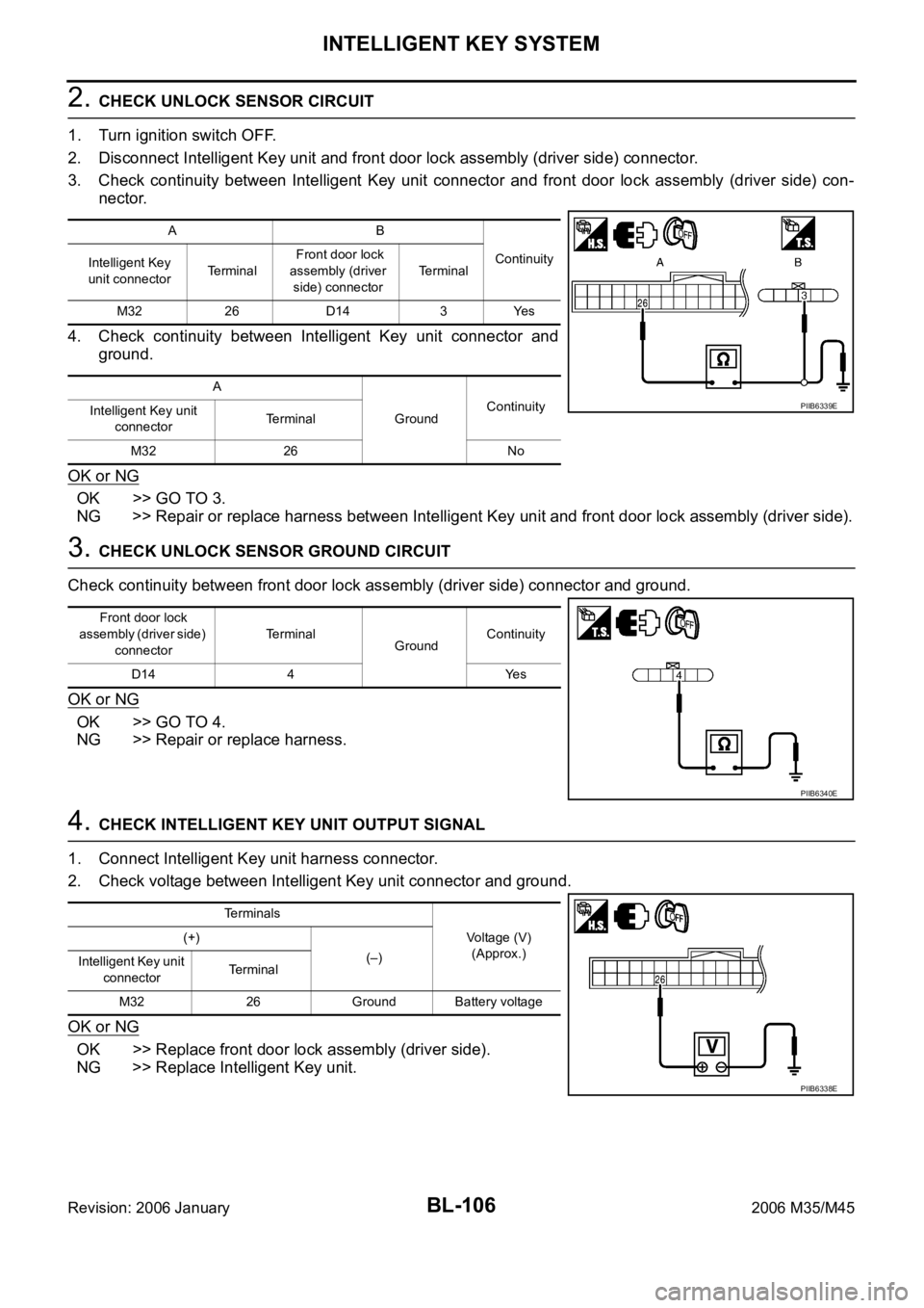
2. CHECK UNLOCK SENSOR CIRCUIT
1. Turn ignition switch OFF.
2. Disconnect Intelligent Key unit and front door lock assembly (driver side) connector.
3. Check continuity between Intelligent Key unit connector and front door lock assembly (driver side) con-
nector.
4. Check continuity between Intelligent Key unit connector and
ground.
OK or NG
OK >> GO TO 3.
NG >> Repair or replace harness between Intelligent Key unit and front door lock assembly (driver side).
3. CHECK UNLOCK SENSOR GROUND CIRCUIT
Check continuity between front door lock assembly (driver side) connector and ground.
OK or NG
OK >> GO TO 4.
NG >> Repair or replace harness.
4. CHECK INTELLIGENT KEY UNIT OUTPUT SIGNAL
1. Connect Intelligent Key unit harness connector.
2. Check voltage between Intelligent Key unit connector and ground.
OK or NG
OK >> Replace front door lock assembly (driver side).
NG >> Replace Intelligent Key unit.
AB
Continuity
Intelligent Key
unit connectorTe r m i n a l Front door lock
assembly (driver
side) connectorTerminal
M32 26 D14 3 Yes
A
GroundContinuity
Intelligent Key unit
connectorTerminal
M32 26 No
PIIB6339E
Front door lock
assembly (driver side)
connectorTerminal
GroundContinuity
D14 4 Yes
PIIB6340E
Terminals
Voltage (V)
(Approx.) (+)
(–)
Intelligent Key unit
connectorTerminal
M32 26 Ground Battery voltage
PIIB6338E
Page 1046 of 5621

INTELLIGENT KEY SYSTEM
BL-107
C
D
E
F
G
H
J
K
L
MA
B
BL
Revision: 2006 January2006 M35/M45
Check Intelligent Key Warning BuzzerNIS001XT
1. CHECK INTELLIGENT KEY WARNING BUZZER
Check voltage between Intelligent Key unit connector and ground.
OK or NG
OK >> Intelligent Key warning buzzer is OK.
NG >> GO TO 2.
2. CHECK INTELLIGENT KEY WARNING BUZZER POWER SUPPLY CIRCUIT
1. Turn ignition switch OFF.
2. Disconnect Intelligent Key warning buzzer connector.
3. Check voltage between Intelligent Key warning buzzer connector and ground.
OK or NG
OK >> GO TO 3.
NG >> Repair or replace Intelligent Key warning buzzer power
supply circuit.
3. CHECK INTELLIGENT KEY WARNING BUZZER CIRCUIT
1. Disconnect Intelligent Key unit connector.
2. Check continuity between Intelligent Key unit connector and Intelligent Key warning buzzer connector.
3. Check continuity between Intelligent Key unit connector and
ground.
OK or NG
OK >> GO TO 4.
NG >> Repair or replace harness between Intelligent Key unit and Intelligent Key warning buzzer.
Te r m i n a l s
Warning
buzzer opera-
tion conditionVoltage (V)
(Approx.) (+)
(–)
Intelligent Key
unit connectorTerminal
M33 55 GroundYe s 0
No Battery voltage
PIIB6341E
Terminals
Voltage (V)
(Approx.) (+)
(–) Intelligent Key
warning buzzer
connectorTerminal
E37 3 Ground Battery voltage
PIIB6342E
AB
Continuity
Intelligent Key
unit connectorTerminalIntelligent Key
warning buzzer
connectorTerminal
M33 55 E37 1 Yes
A
GroundContinuity
Intelligent Key unit
connectorTerminal
M33 55 No
PIIB6343E