2006 INFINITI M35 Ras
[x] Cancel search: RasPage 5133 of 5621

SB-34
SEAT BELTS
Revision: 2006 January2006 M35/M45
NOTE:
Apply the tape so that there is no looseness or wrinkling.
6. Remove the clip fixing the seat belt and check that the webbing returns smoothly.
6. Repeat steps above as necessary to check the other seat belts.
SEAT BELT RETRACTOR ON-VEHICLE CHECK
Emergency Locking Retractors (ELR) and Automatic Locking Retractors (ALR)
NOTE:
All seat belt retractors are of the Emergency Locking Retractors (ELR) type. In an emergency (sudden stop)
the retractor will lock and prevent the webbing from extending any further. All 3-point type seat belt retractors
except the driver's seat belt also have an Automatic Locking Retractors (ALR) mode. The ALR mode (also
called child restraint mode) is used when installing child seats. The ALR mode is activated when the seat belt
is fully extended. When the webbing is then retracted partially, the ALR mode automatically locks the seat belt
in a specific position so the webbing cannot be extended any further. To cancel the ALR mode, allow the seat
belt to fully wind back into the retractor.
Check the seat belt retractors using the following test(s) to determine if a retractor assembly is operating prop-
erly.
ELR Function Stationary Check
Grasp the shoulder webbing and pull forward quickly. The retractor should lock and prevent the belt from
extending further.
ALR Function Stationary Check
1. Pull out entire length of seat belt from retractor until a click is heard.
2. Retract the webbing partially. A clicking noise should be heard as the webbing retracts indicating that the
retractor is in the Automatic Locking Retractors (ALR) mode.
3. Grasp the seat belt and try to pull out the retractor. The webbing must lock and not extend any further. If
NG, replace the retractor assembly.
4. Allow the entire length of the webbing to retract to cancel the automatic locking mode.
ELR Function Moving Check
WAR NING :
Perform the following test in a safe, open area clear of other vehicles and obstructions (for example, a
large, empty parking lot). Road surface must be paved and dry. DO NOT perform the following test on
wet or gravel roads or on public streets and highways. This could result in an accident and serious
personal injury. The driver and passenger must be prepared to brace themselves in the event the
retractor does not lock.
1. Fasten driver's seat belt. Buckle a passenger into the seat for the belt that is to be tested.
2. Proceed to the designated safe area.
3. Drive the vehicle at approximately 16 km/h (10 MPH). Notify any passengers of a pending sudden stop
and the driver and passenger must be prepared to brace themselves in the event the retractor does not
lock, apply brakes firmly and make a very hard stop.
During stop, seat belts should lock and not be extended. If the seat belt retractor assembly does not lock, per-
form the retractor off-vehicle check.
Page 5165 of 5621

SC-28
CHARGING SYSTEM
Revision: 2006 January2006 M35/M45
Trouble Diagnoses with Battery/Starting/Charging System Tester (Charging)NKS003NP
NOTE:
To ensure a complete and thorough diagnosis, the battery, starter and alternator test segments must be done
as a set from start to finish.
Before starting, perform the preliminary inspection. Refer to SC-32, "
PRELIMINARY INSPECTION" .
1. Stop the operation of the power generation voltage variable control in either of the following procedures.
After selecting “ENGINE” of “SELECT SYSTEM” using CONSULT-II, set the DUTY value of “ALTERNA-
TOR DUTY” to 0% by selecting “ALTERNATOR DUTY” of “ACTIVE TEST”. Continue “ACTIVE TEST”
until the end of inspection. (When the DUTY value is 0 or 100%, the normal power generation is per-
formed according to the characteristic of the IC regulator of the alternator.)
Turn the ignition switch OFF, and disconnect the battery current sensor connector. [However, DTC
(P1550 - P1554) of the engine might remain. After finishing the inspection, connect the battery current
sensor connector and erase the self-diagnostic results history of the engine using CONSULT-II.]
2. Turn off all loads on the vehicle electrical system.
3. Perform battery and starting system test with Battery/Starting/
Charging system tester.
4. Press “ENTER” to begin the charging system test.
5. Start engine.
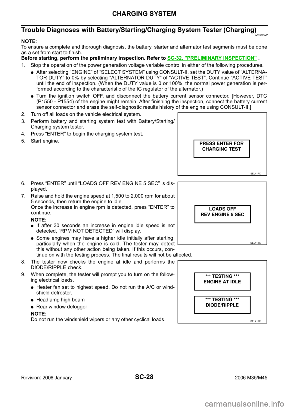
6. Press “ENTER” until “LOADS OFF REV ENGINE 5 SEC” is dis-
played.
7. Raise and hold the engine speed at 1,500 to 2,000 rpm for about
5 seconds, then return the engine to idle.
Once the increase in engine rpm is detected, press “ENTER” to
continue.
NOTE:
If after 30 seconds an increase in engine idle speed is not
detected, “RPM NOT DETECTED” will display.
Some engines may have a higher idle initially after starting,
particularly when the engine is cold. The tester may detect
this without any other action being taken. If this occurs, con-
tinue on with the testing process. The final results will not be affected.
8. The tester now checks the engine at idle and performs the
DIODE/RIPPLE check.
9. When complete, the tester will prompt you to turn on the follow-
ing electrical loads.
Heater fan set to highest speed. Do not run the A/C or wind-
shield defroster.
Headlamp high beam
Rear window defogger
NOTE:
Do not run the windshield wipers or any other cyclical loads.
SEL417X
SEL418X
SEL419X
Page 5194 of 5621

AUTOMATIC DRIVE POSITIONER
SE-13
C
D
E
F
G
H
J
K
L
MA
B
SE
Revision: 2006 January2006 M35/M45
*: Door mirror operation starts with the start of seat sliding operation.
Storing Memory Procedure
1. Turn ignition switch to ON.
2. Shift A/T selector lever to P position.
3. Adjust position of driver seat, steering and mirror position.
4. Press set switch.
Indicator LED for which driver seat positions are already retained in memory is illuminated for 5 sec-
onds.
Indicator LED for which driver seat positions are not retained in memory is illuminated for 0.5 second.
5. Press memory switch for which driver seat positions are to be entered in memory for more than 0.5 sec-
ond within 5 seconds after pressing the set switch (during the indicator LED is illuminated).
To enter driver seat positions in blank memory, indicator LED will be illuminated for 5 seconds.
To modify driver seat positions, indicator LED will be turned OFF for 0.5 second then illuminated for 5
seconds.
6.
If you need setting of INTELLIGENT KEY INTERLOCK OPERATION, continue this procedure.
If you don't need setting of INTELLIGENT KEY INTERLOCK OPERATION, the procedure is finished.
Conform the operations of each part with the MEMORY OPERATION.
7. Press intelligent key unlock button within 5 seconds after pressing memory switch.
(While memory switch LED is illuminated.)
8. Conform the operations of each part with MEMORY OPERATION and INTELLIGENT KEY INTERLOCK
OPERATION.
NOTE:
Driving position is erased from the memory when battery cable is disconnected.
Order of priority Operated portion
1* Seat sliding
2 Steering telescopic
3 Steering wheel tilt
4 Seat reclining
5 Seat lifter (front)
6 Seat lifter (rear)
Page 5217 of 5621

SE-36
AUTOMATIC DRIVE POSITIONER
Revision: 2006 January2006 M35/M45
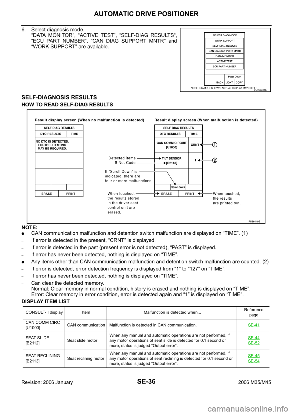
6. Select diagnosis mode.
“DATA MONITOR”, “ACTIVE TEST”, “SELF-DIAG RESULTS“,
“ECU PART NUMBER”, “CAN DIAG SUPPORT MNTR” and
“WORK SUPPORT” are available.
SELF-DIAGNOSIS RESULTS
HOW TO READ SELF-DIAG RESULTS
NOTE:
CAN communication malfunction and detention switch malfunction are displayed on “TIME”. (1)
–If error is detected in the present, “CRNT” is displayed.
–If error is detected in the past (present error is not detected), “PAST” is displayed.
–If error has never been detected, nothing is displayed on “TIME”.
Any items other than CAN communication malfunction and detention switch malfunction are counted. (2)
–If error is detected, error detection frequency is displayed from “1” to “127” on “TIME”.
–If error has never been detected, nothing is displayed on “TIME”.
–Can clear the detected memory.
Normal: Clear memory in normal condition, history is erased and nothing is displayed on “TIME”.
Error: Clear memory in error condition, error is detected again and “1” is displayed on “TIME”.
DISPLAY ITEM LIST
BCIA0031E
CONSULT-II display Item Malfunction is detected when...Reference
page
CAN COMM CIRC
[U1000]CAN communication Malfunction is detected in CAN communication.SE-41
SEAT SLIDE
[B2112]Seat slide motorWhen any manual and automatic operations are not performed, if
any motor operations of seat slide is detected for 0.1 second or
more, status is judged “Output error”.SE-44
SE-52
SEAT RECLINING
[B2113]Seat reclining motorWhen any manual and automatic operations are not performed, if
any motor operations of seat reclining is detected for 0.1 second or
more, status is judged “Output error”.SE-45
SE-54
PIIB6449E
Page 5362 of 5621

SRS-1
SUPPLEMENTAL RESTRAINT SYSTEM (SRS)
H RESTRAINTS
CONTENTS
C
D
E
F
G
I
J
K
L
M
SECTION SRS
A
B
SRS
Revision: 2006 January2006 M35/M45
SUPPLEMENTAL RESTRAINT SYSTEM (SRS)
PRECAUTIONS .......................................................... 3
Precautions for Supplemental Restraint System
(SRS) “AIR BAG” and “SEAT BELT PRE-TEN-
SIONER” .................................................................. 3
Precautions for SRS “AIR BAG” and “SEAT BELT
PRE-TENSIONER” Service ..................................... 3
Occupant Classification System Precaution ............ 3
PREPARATION ........................................................... 4
Commercial Service Tools ........................................ 4
SUPPLEMENTAL RESTRAINT SYSTEM (SRS) ....... 5
SRS Configuration ..............................................
..... 5
Front Seat Belt Pre-Tensioner with Load Limiter ...... 6
Front Side Air Bag .................................................... 6
Side Curtain Air Bag ................................................. 6
Occupant Classification System (OCS) ................... 7
Passenger Air Bag Status Condition ........................ 7
Component Parts of Occupant Classification Sys-
tem ........................................................................... 7
TROUBLE DIAGNOSIS .............................................. 8
Trouble Diagnosis Introduction ................................. 8
DIAGNOSIS FUNCTION ....................................... 8
HOW TO PERFORM TROUBLE DIAGNOSIS
FOR QUICK AND ACCURATE REPAIR ............... 8
WORK FLOW ........................................................ 9
Component Parts Location ..................................... 10
Schematic ............................................................... 11
Wiring Diagram — SRS — ..................................... 12
CONSULT-II Function ............................................ 17
DIAGNOSIS MODE FOR CONSULT-II ............... 17
HOW TO CHANGE SELF-DIAGNOSIS MODE
WITH CONSULT-II .............................................. 17
HOW TO ERASE SELF-DIAGNOSTIC
RESULTS ............................................................ 18
Self-Diagnosis Function (Without CONSULT-II) ..... 18
HOW TO CHANGE SELF-DIAGNOSIS MODE
WITHOUT CONSULT-II ...................................... 18
HOW TO ERASE SELF-DIAGNOSTIC
RESULTS ............................................................ 18
SRS Operation Check ............................................ 19
DIAGNOSTIC PROCEDURE 1 ........................... 19Trouble Diagnosis with CONSULT-II ...................... 21
DIAGNOSTIC PROCEDURE 2 ........................... 21
DIAGNOSTIC PROCEDURE 3 ........................... 25
DIAGNOSTIC PROCEDURE 4 (CONTINUED
FROM DIAGNOSTIC PROCEDURE 2) .............. 27
DIAGNOSTIC PROCEDURE 5 ........................... 27
Trouble Diagnosis without CONSULT-II ................. 32
DIAGNOSTIC PROCEDURE 6 ........................... 32
WARNING LAMP FLASH CODE CHART ........... 32
Trouble Diagnosis: “AIR BAG” Warning Lamp Does
Not Turn OFF ......................................................... 36
DIAGNOSTIC PROCEDURE 7 ........................... 36
Trouble Diagnosis: “AIR BAG” Warning Lamp Does
Not Turn ON ........................................................... 37
DIAGNOSTIC PROCEDURE 8 ........................... 37
DRIVER AIR BAG MODULE .................................... 38
Removal and Installation ........................................ 38
REMOVAL ........................................................
... 38
INSTALLATION ................................................... 39
SPIRAL CABLE ........................................................ 40
Removal and Installation ........................................ 40
REMOVAL ........................................................
... 40
INSTALLATION ................................................... 40
FRONT PASSENGER AIR BAG MODULE .............. 42
Removal and Installation ........................................ 42
REMOVAL ........................................................
... 42
INSTALLATION ................................................... 42
SIDE CURTAIN AIR BAG MODULE ........................ 43
Removal and Installation ........................................ 43
REMOVAL ........................................................
... 43
INSTALLATION ................................................... 44
CRASH ZONE SENSOR ........................................... 45
Removal and Installation ........................................ 45
REMOVAL ........................................................
... 45
INSTALLATION ................................................... 45
SIDE AIR BAG (SATELLITE) SENSOR ................... 46
Removal and Installation ........................................ 46
REMOVAL ........................................................
... 46
INSTALLATION ................................................... 46
Page 5371 of 5621

SRS-10
TROUBLE DIAGNOSIS
Revision: 2006 January2006 M35/M45
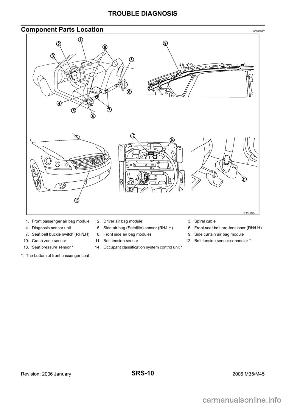
Component Parts LocationNHS00091
*: The bottom of front passenger seat
PHIA1110E
1. Front passenger air bag module 2. Driver air bag module 3. Spiral cable
4. Diagnosis sensor unit 5. Side air bag (Satellite) sensor (RH/LH) 6. Front seat belt pre-tensioner (RH/LH)
7. Seat belt buckle switch (RH/LH) 8. Front side air bag modules 9.Side curtain air bag module
10. Crash zone sensor 11. Belt tension sensor 12. Belt tension sensor connector *
13. Seat pressure sensor * 14. Occupant classification system control unit *
Page 5378 of 5621
![INFINITI M35 2006 Factory Service Manual TROUBLE DIAGNOSIS
SRS-17
C
D
E
F
G
I
J
K
L
MA
B
SRS
Revision: 2006 January2006 M35/M45
CONSULT-II FunctionNHS00094
DIAGNOSIS MODE FOR CONSULT-II
“SELF-DIAG [CURRENT]”
A current self-diagnosis r INFINITI M35 2006 Factory Service Manual TROUBLE DIAGNOSIS
SRS-17
C
D
E
F
G
I
J
K
L
MA
B
SRS
Revision: 2006 January2006 M35/M45
CONSULT-II FunctionNHS00094
DIAGNOSIS MODE FOR CONSULT-II
“SELF-DIAG [CURRENT]”
A current self-diagnosis r](/manual-img/42/57023/w960_57023-5377.png)
TROUBLE DIAGNOSIS
SRS-17
C
D
E
F
G
I
J
K
L
MA
B
SRS
Revision: 2006 January2006 M35/M45
CONSULT-II FunctionNHS00094
DIAGNOSIS MODE FOR CONSULT-II
“SELF-DIAG [CURRENT]”
A current self-diagnosis results (also indicated by the number of warning lamp flashes in the Diagnosis
mode) is displayed on the CONSULT-II screen in real time. This refers to a malfunctioning part requiring
repairs.
“SELF-DIAG [PAST]”
Diagnosis results previously stored in the memory are displayed on the CONSULT-II screen. The stored
results are not erased until memory erasing is executed.
“TROUBLE DIAG RECORD”
With TROUBLE DIAG RECORD, diagnosis results previously erased by a reset operation can be dis-
played on the CONSULT-II screen.
“ECU DISCRIMINATED NO.”
The diagnosis sensor unit for each vehicle model is assigned
with its own, individual classification number. This number will
be displayed on the CONSULT-II screen, as shown. When
replacing the diagnosis sensor unit, refer to the part number for
the compatibility. After installation, replacement with a correct
unit can be checked by confirming this classification number on
the CONSULT-II screen.
After repair, make sure the discriminated number of diagnosis
sensor unit installed to vehicle are same. Refer to SRS-48,
"ECU DISCRIMINATED NO." .
PASSENGER AIR BAG
The STATUS (Readiness) of the front passenger air bag module is displayed.The STATUS displayed
(ON/OFF) depends on the signals supplied to the occupant classification system control module and
air bag diagnosis sensor unit. Refer to SRS-7, "
Occupant Classification System (OCS)" for more infoma-
tion.
HOW TO CHANGE SELF-DIAGNOSIS MODE WITH CONSULT-II
From User Mode to Diagnosis Mode
After selecting “AIR BAG” on the “SELECT SYSTEM” screen, User mode automatically changes to Diagnosis
mode.
From Diagnosis Mode to User Mode
To return to User mode from Diagnosis mode, touch “BACK” key of CONSULT-II until “SELECT SYSTEM”
appears, then diagnosis mode automatically changes to User mode.
PHIA0218E
SRS803
SRS804
Page 5379 of 5621
![INFINITI M35 2006 Factory Service Manual SRS-18
TROUBLE DIAGNOSIS
Revision: 2006 January2006 M35/M45
HOW TO ERASE SELF-DIAGNOSTIC RESULTS
“SELF-DIAG [CURRENT]”
A current self-diagnosis result is displayed on the CONSULT-II screen in real INFINITI M35 2006 Factory Service Manual SRS-18
TROUBLE DIAGNOSIS
Revision: 2006 January2006 M35/M45
HOW TO ERASE SELF-DIAGNOSTIC RESULTS
“SELF-DIAG [CURRENT]”
A current self-diagnosis result is displayed on the CONSULT-II screen in real](/manual-img/42/57023/w960_57023-5378.png)
SRS-18
TROUBLE DIAGNOSIS
Revision: 2006 January2006 M35/M45
HOW TO ERASE SELF-DIAGNOSTIC RESULTS
“SELF-DIAG [CURRENT]”
A current self-diagnosis result is displayed on the CONSULT-II screen in real time.
After the malfunction is repaired completely, no malfunction is detected on “SELF-DIAG [CURRENT]”.
“SELF-DIAG [PAST]”
Return to the “SELF-DIAG [CURRENT]” CONSULT-II screen by touching “BACK” key of CONSULT-II and
select “SELF-DIAG [CURRENT]” in SELECT DIAG MODE. Touch “ERASE” in “SELF-DIAG [CURRENT]”
mode.
NOTE:
If the memory of the malfunction in “SELF-DIAG [PAST]” is not erased, the User mode shows the system
malfunction by the operation of the warning lamp even if the malfunction is repaired completely.
“TROUBLE DIAG RECORD”
The memory of “TROUBLE DIAG RECORD” cannot be erased.
Self-Diagnosis Function (Without CONSULT-II)NHS00095
The reading of these results is accomplished “User mode” and “Diagnosis mode”.
After a malfunction is repaired, turn ignition switch ON. Diagnosis mode returns to the User mode. At that
time, the self-diagnosis result is cleared.
HOW TO CHANGE SELF-DIAGNOSIS MODE WITHOUT CONSULT-II
HOW TO ERASE SELF-DIAGNOSTIC RESULTS
After a malfunction is repaired, turn the ignition switch OFF for at least one second, then back ON. Diagnosis
mode returns to the User mode. At that time, the self-diagnosis result is cleared.
SRS701
PHIA0709E