Page 3373 of 5621

FAX-14
FRONT DRIVE SHAFT
Revision: 2006 January2006 M35/M45
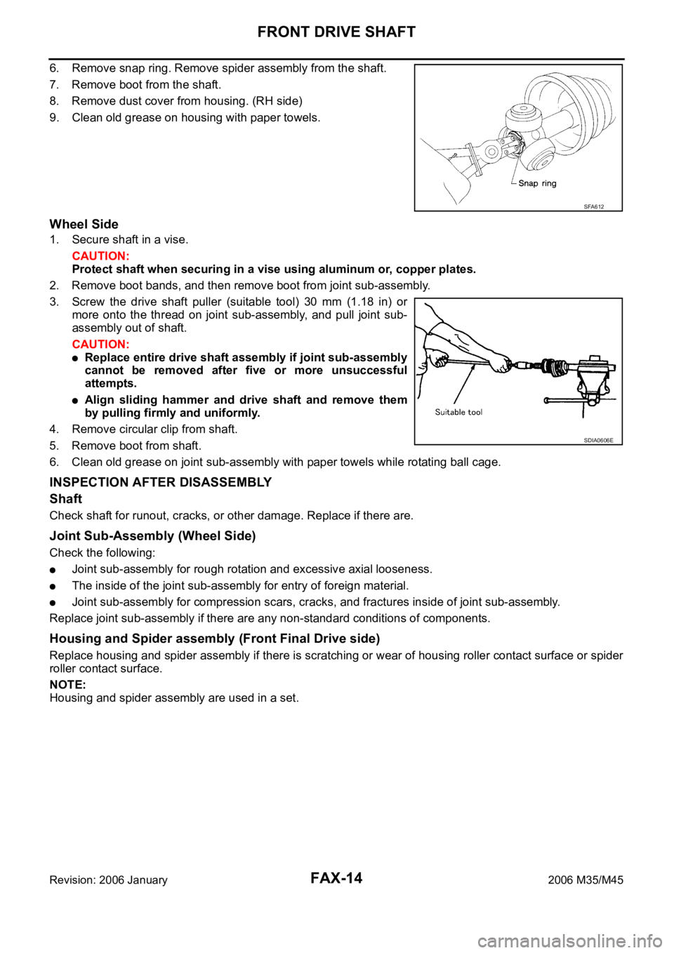
6. Remove snap ring. Remove spider assembly from the shaft.
7. Remove boot from the shaft.
8. Remove dust cover from housing. (RH side)
9. Clean old grease on housing with paper towels.
Wheel Side
1. Secure shaft in a vise.
CAUTION:
Protect shaft when securing in a vise using aluminum or, copper plates.
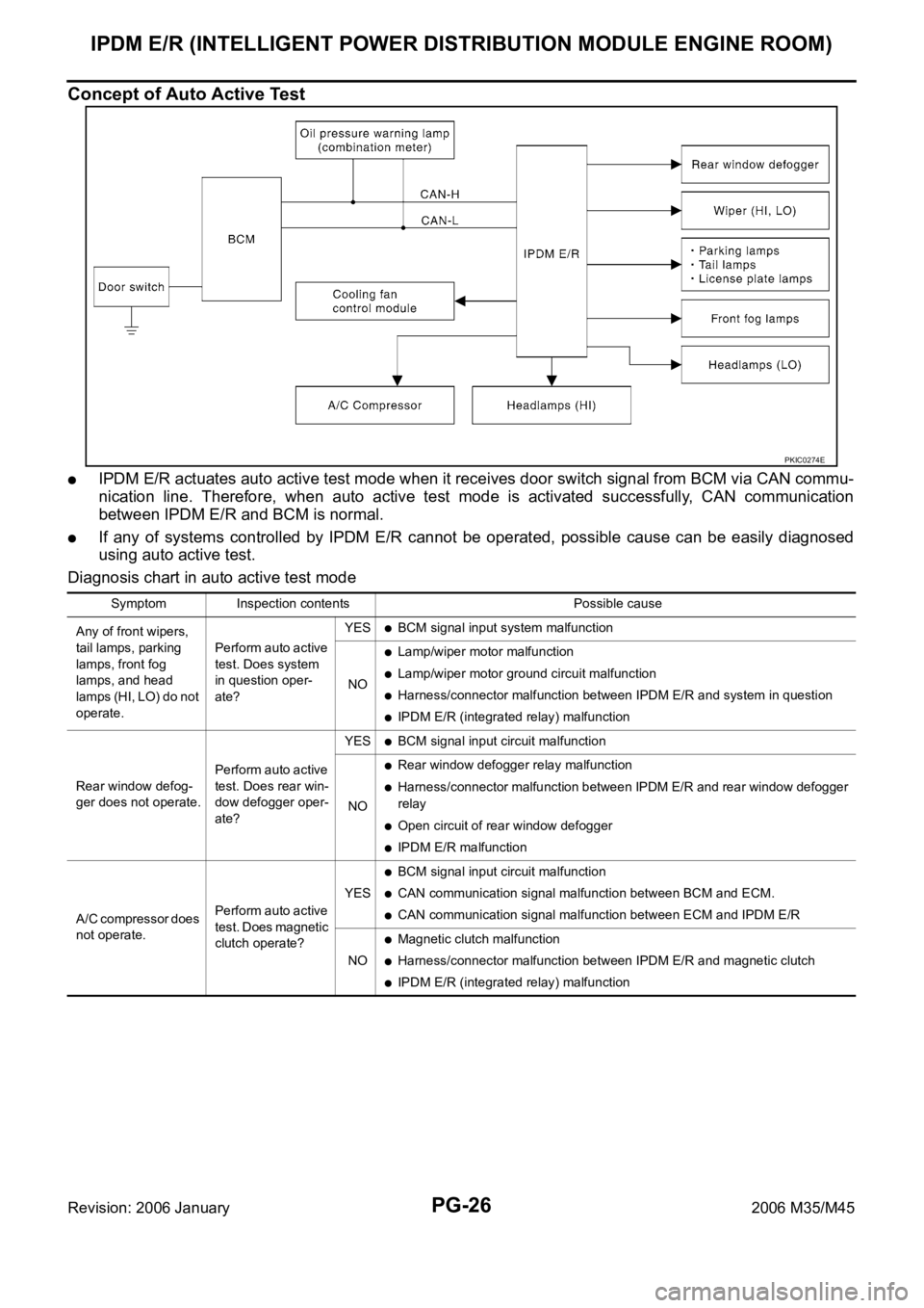
2. Remove boot bands, and then remove boot from joint sub-assembly.
3. Screw the drive shaft puller (suitable tool) 30 mm (1.18 in) or
more onto the thread on joint sub-assembly, and pull joint sub-
assembly out of shaft.
CAUTION:
Replace entire drive shaft assembly if joint sub-assembly
cannot be removed after five or more unsuccessful
attempts.
Align sliding hammer and drive shaft and remove them
by pulling firmly and uniformly.
4. Remove circular clip from shaft.
5. Remove boot from shaft.
6. Clean old grease on joint sub-assembly with paper towels while rotating ball cage.
INSPECTION AFTER DISASSEMBLY
Shaft
Check shaft for runout, cracks, or other damage. Replace if there are.
Joint Sub-Assembly (Wheel Side)
Check the following:
Joint sub-assembly for rough rotation and excessive axial looseness.
The inside of the joint sub-assembly for entry of foreign material.
Joint sub-assembly for compression scars, cracks, and fractures inside of joint sub-assembly.
Replace joint sub-assembly if there are any non-standard conditions of components.
Housing and Spider assembly (Front Final Drive side)
Replace housing and spider assembly if there is scratching or wear of housing roller contact surface or spider
roller contact surface.
NOTE:
Housing and spider assembly are used in a set.
SFA612
SDIA0606E
Page 4853 of 5621

PG-26
IPDM E/R (INTELLIGENT POWER DISTRIBUTION MODULE ENGINE ROOM)
Revision: 2006 January2006 M35/M45
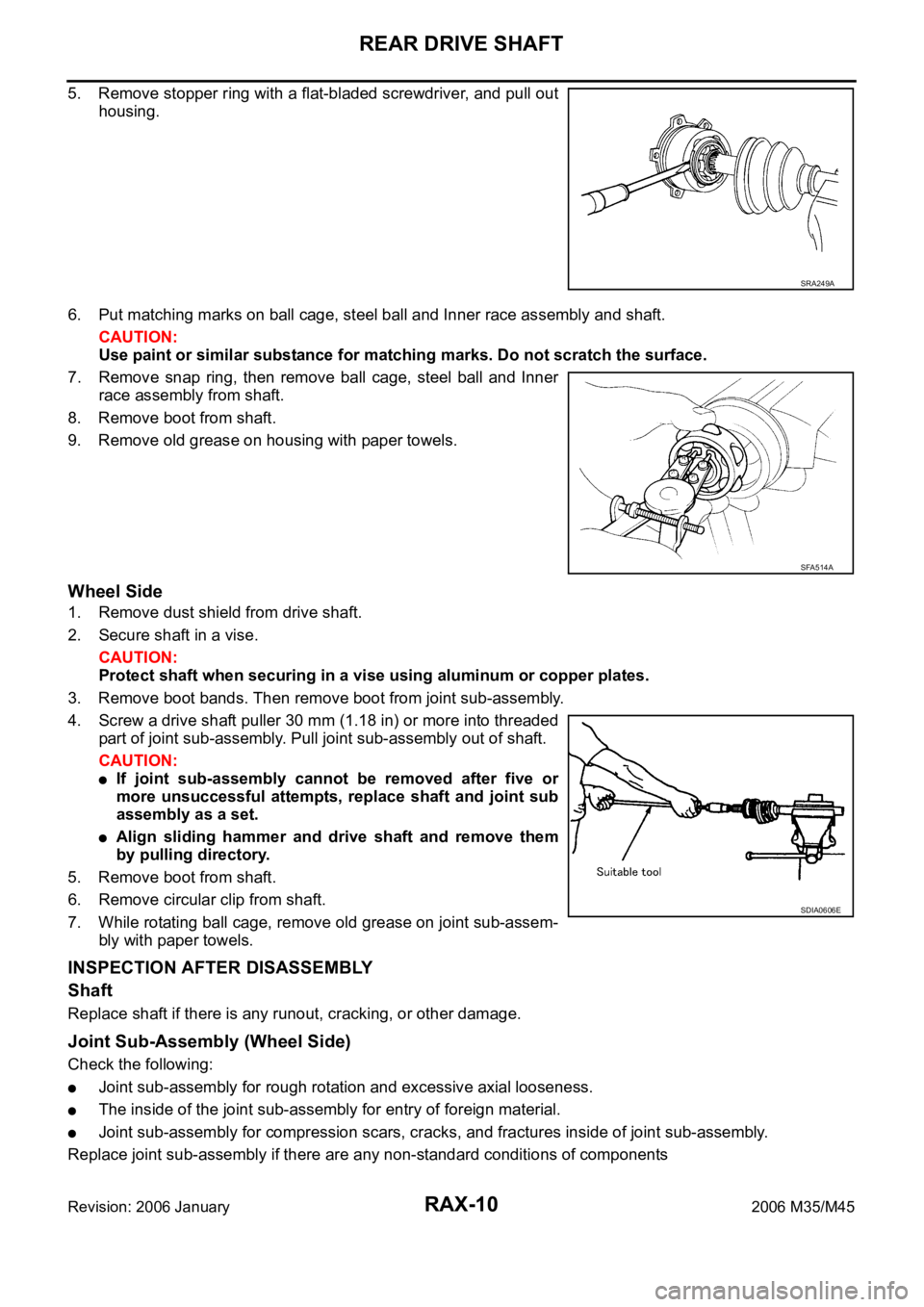
Concept of Auto Active Test
IPDM E/R actuates auto active test mode when it receives door switch signal from BCM via CAN commu-
nication line. Therefore, when auto active test mode is activated successfully, CAN communication
between IPDM E/R and BCM is normal.
If any of systems controlled by IPDM E/R cannot be operated, possible cause can be easily diagnosed
using auto active test.
Diagnosis chart in auto active test mode
PKIC0274E
Symptom Inspection contents Possible cause
Any of front wipers,
tail lamps, parking
lamps, front fog
lamps, and head
lamps (HI, LO) do not
operate.Perform auto active
test. Does system
in question oper-
ate?YES
BCM signal input system malfunction
NO
Lamp/wiper motor malfunction
Lamp/wiper motor ground circuit malfunction
Harness/connector malfunction between IPDM E/R and system in question
IPDM E/R (integrated relay) malfunction
Rear window defog-
ger does not operate.Perform auto active
test. Does rear win-
dow defogger oper-
ate?YES
BCM signal input circuit malfunction
NO
Rear window defogger relay malfunction
Harness/connector malfunction between IPDM E/R and rear window defogger
relay
Open circuit of rear window defogger
IPDM E/R malfunction
A/C compressor does
not operate.Perform auto active
test. Does magnetic
clutch operate?YES
BCM signal input circuit malfunction
CAN communication signal malfunction between BCM and ECM.
CAN communication signal malfunction between ECM and IPDM E/R
NO
Magnetic clutch malfunction
Harness/connector malfunction between IPDM E/R and magnetic clutch
IPDM E/R (integrated relay) malfunction
Page 5009 of 5621

RAX-10
REAR DRIVE SHAFT
Revision: 2006 January2006 M35/M45
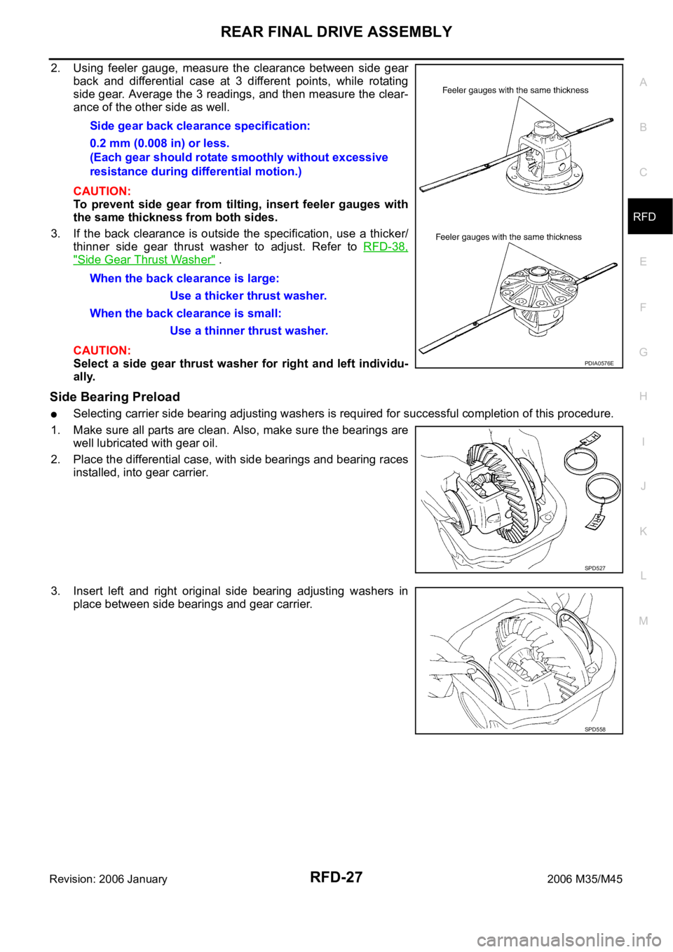
5. Remove stopper ring with a flat-bladed screwdriver, and pull out
housing.
6. Put matching marks on ball cage, steel ball and Inner race assembly and shaft.
CAUTION:
Use paint or similar substance for matching marks. Do not scratch the surface.
7. Remove snap ring, then remove ball cage, steel ball and Inner
race assembly from shaft.
8. Remove boot from shaft.
9. Remove old grease on housing with paper towels.
Wheel Side
1. Remove dust shield from drive shaft.
2. Secure shaft in a vise.
CAUTION:
Protect shaft when securing in a vise using aluminum or copper plates.
3. Remove boot bands. Then remove boot from joint sub-assembly.
4. Screw a drive shaft puller 30 mm (1.18 in) or more into threaded
part of joint sub-assembly. Pull joint sub-assembly out of shaft.
CAUTION:
If joint sub-assembly cannot be removed after five or
more unsuccessful attempts, replace shaft and joint sub
assembly as a set.
Align sliding hammer and drive shaft and remove them
by pulling directory.
5. Remove boot from shaft.
6. Remove circular clip from shaft.
7. While rotating ball cage, remove old grease on joint sub-assem-
bly with paper towels.
INSPECTION AFTER DISASSEMBLY
Shaft
Replace shaft if there is any runout, cracking, or other damage.
Joint Sub-Assembly (Wheel Side)
Check the following:
Joint sub-assembly for rough rotation and excessive axial looseness.
The inside of the joint sub-assembly for entry of foreign material.
Joint sub-assembly for compression scars, cracks, and fractures inside of joint sub-assembly.
Replace joint sub-assembly if there are any non-standard conditions of components
SRA249A
SFA514A
SDIA0606E
Page 5070 of 5621

REAR FINAL DRIVE ASSEMBLY
RFD-27
C
E
F
G
H
I
J
K
L
MA
B
RFD
Revision: 2006 January2006 M35/M45
2. Using feeler gauge, measure the clearance between side gear
back and differential case at 3 different points, while rotating
side gear. Average the 3 readings, and then measure the clear-
ance of the other side as well.
CAUTION:
To prevent side gear from tilting, insert feeler gauges with
the same thickness from both sides.
3. If the back clearance is outside the specification, use a thicker/
thinner side gear thrust washer to adjust. Refer to RFD-38,
"Side Gear Thrust Washer" .
CAUTION:
Select a side gear thrust washer for right and left individu-
ally.
Side Bearing Preload
Selecting carrier side bearing adjusting washers is required for successful completion of this procedure.
1. Make sure all parts are clean. Also, make sure the bearings are
well lubricated with gear oil.
2. Place the differential case, with side bearings and bearing races
installed, into gear carrier.
3. Insert left and right original side bearing adjusting washers in
place between side bearings and gear carrier.Side gear back clearance specification:
0.2 mm (0.008 in) or less.
(Each gear should rotate smoothly without excessive
resistance during differential motion.)
When the back clearance is large:
Use a thicker thrust washer.
When the back clearance is small:
Use a thinner thrust washer.
PDIA0576E
SPD527
SPD558