Page 5052 of 5621

DIFFERENTIAL GEAR OIL
RFD-9
C
E
F
G
H
I
J
K
L
MA
B
RFD
Revision: 2006 January2006 M35/M45
DIFFERENTIAL GEAR OILPFP:KLD30
Changing Differential Gear OilNDS000F3
DRAINING
1. Stop engine.
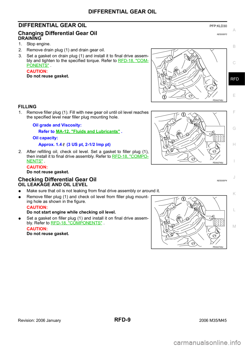
2. Remove drain plug (1) and drain gear oil.
3. Set a gasket on drain plug (1) and install it to final drive assem-
bly and tighten to the specified torque. Refer to RFD-18, "
COM-
PONENTS" .
CAUTION:
Do not reuse gasket.
FILLING
1. Remove filler plug (1). Fill with new gear oil until oil level reaches
the specified level near filler plug mounting hole.
2. After refilling oil, check oil level. Set a gasket to filler plug (1),
then install it to final drive assembly. Refer to RFD-18, "
COMPO-
NENTS" .
CAUTION:
Do not reuse gasket.
Checking Differential Gear OilNDS000F4
OIL LEAKAGE AND OIL LEVEL
Make sure that oil is not leaking from final drive assembly or around it.
Remove filler plug (1) and check oil level from filler plug mount-
ing hole as shown in the figure.
CAUTION:
Do not start engine while checking oil level.
Set a gasket on filler plug (1) and install it on final drive assem-
bly. Refer to RFD-18, "
COMPONENTS" .
CAUTION:
Do not reuse gasket.
PDIA0748J
Oil grade and Viscosity:
Refer to MA-12, "
Fluids and Lubricants" .
Oil capacity:
Approx. 1.4 (3 US pt, 2-1/2 Imp pt)
PDIA0749J
PDIA0749J
Page 5083 of 5621
RSU-2
PRECAUTIONS
Revision: 2006 January2006 M35/M45
PRECAUTIONSPFP:00001
PrecautionsNES000J2
When installing rubber bushings, final tightening must be carried out under unladen conditions with tires
on ground. Oil will shorten the life of rubber bushings. Be sure to wipe off any spilled oil.
–Unladen conditions mean that fuel, engine coolant and lubricant are full. Spare tire, jack, hand tools and
mats are in designated positions.
After servicing suspension parts, be sure to check wheel alignment.
Self-lock nuts are not reusable. Always use new ones when installing. Since new self-lock nuts are pre-
oiled, tighten as they are.
Page 5086 of 5621

REAR SUSPENSION ASSEMBLY
RSU-5
C
D
F
G
H
I
J
K
L
MA
B
RSU
Revision: 2006 January2006 M35/M45
REAR SUSPENSION ASSEMBLYPFP:55020
On-Vehicle Inspection and ServiceNES000J6
Make sure the mounting conditions (looseness, back lash) of each component and component conditions
(wear, damage) are normal.
SUSPENSION ARM BALL JOINT AXIAL END PLAY INSPECTION
Measure axial end play by placing and moving up/down with an iron pry bar or something similar between sus-
pension arm and axle.
CAUTION:
Be careful not to damage ball joint boot.
SHOCK ABSORBER INSPECTION
Check shock absorber for oil leakage, damage and replace if malfunction is detected.
Wheel Alignment InspectionNES000J7
DESCRIPTION
Measure wheel alignment under unladen conditions.
NOTE:
“Unladen conditions” means that fuel, engine coolant, and lubricant are full. Spare tire, jack, hand tools and
mats in designated positions.
PRELIMINARY INSPECTION
Check the following:
1. Tires for improper air pressure and wear.
2. Road wheels for runout. Refer to WT-6, "
ROAD WHEEL" .
3. Wheel bearing axial end play. Refer to RAX-5, "
WHEEL BEARING INSPECTION" .
4. Ball joint axial end play of suspension arm. Refer to RSU-5, "
SUSPENSION ARM BALL JOINT AXIAL
END PLAY INSPECTION" .
5. Shock absorber operation.
6. Each mounting point of axle and suspension for looseness and deformation.
7. Each of front lower link, rear lower link, radius rod, rear suspension member, suspension arm and shock
absorber for cracks, deformation, and other damage.
8. Vehicle height (posture).
GENERAL INFORMATION AND RECOMMENDATIONS
A four-wheel thrust alignment should be performed.
–This type of alignment is recommended for any NISSAN/INFINITI vehicle.
–The four-wheel “thrust” process helps ensure that the vehicle is properly aligned and the steering wheel is
centered.
–The alignment rack itself should be capable of accepting any NISSAN/INFINITI vehicle.
–The rack should be checked to ensure that it is level.
Make sure the machine is properly calibrated.
–Your alignment equipment should be regularly calibrated in order to give correct information.
–Check with the manufacturer of your specific equipment for their recommended Service/Calibration
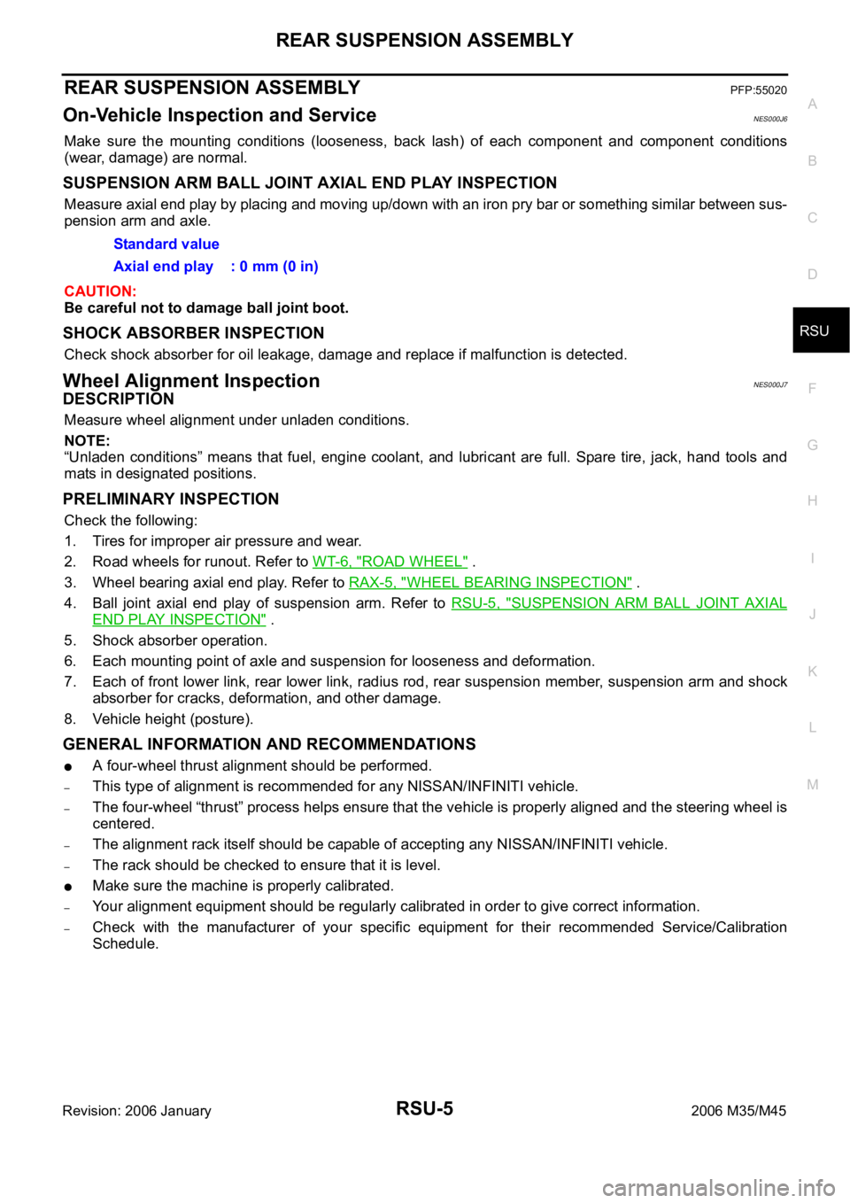
Schedule.Standard value
Axial end play : 0 mm (0 in)
Page 5099 of 5621

RSU-18
SERVICE DATA
Revision: 2006 January2006 M35/M45
SERVICE DATAPFP:00030
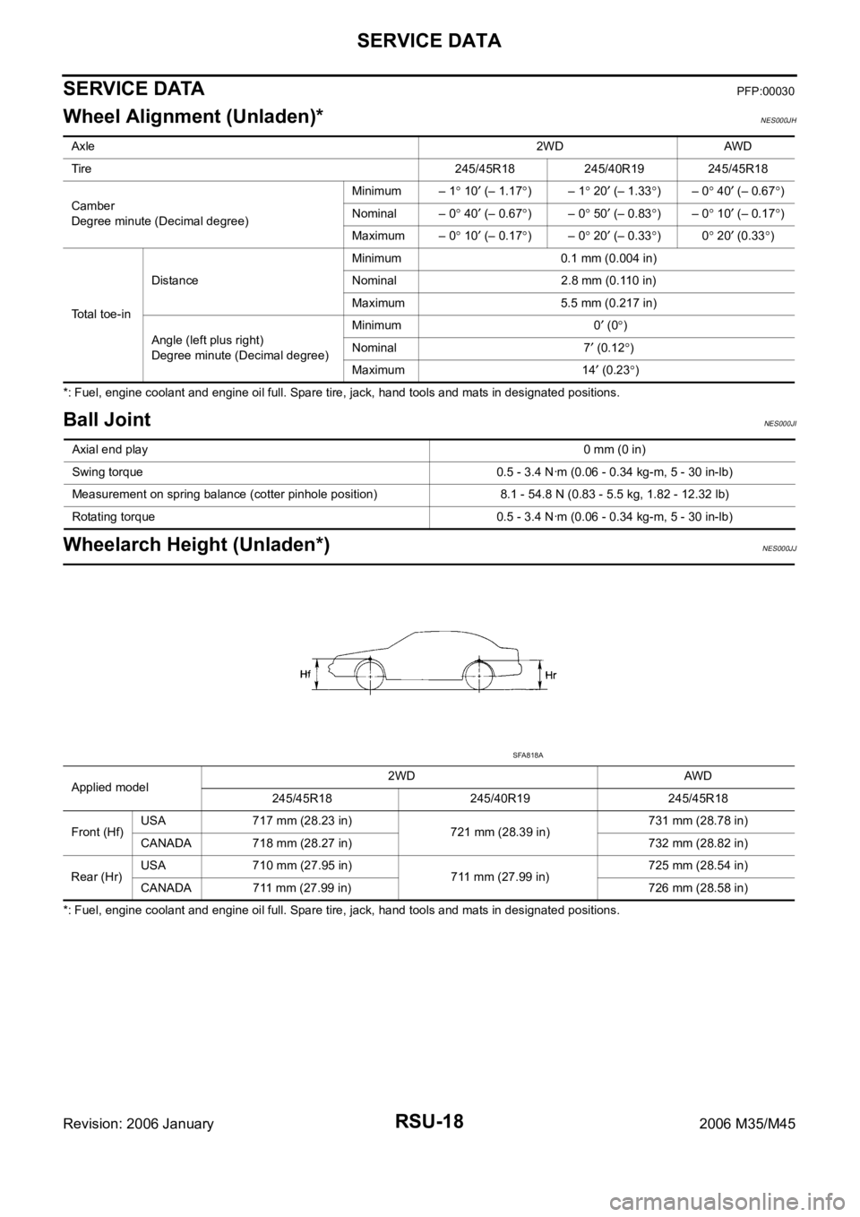
Wheel Alignment (Unladen)*NES000JH
*: Fuel, engine coolant and engine oil full. Spare tire, jack, hand tools and mats in designated positions.
Ball JointNES000JI
Wheelarch Height (Unladen*)NES000JJ
*: Fuel, engine coolant and engine oil full. Spare tire, jack, hand tools and mats in designated positions. Axle2WD AWD
Tire 245/45R18 245/40R19 245/45R18
Camber
Degree minute (Decimal degree)Minimum – 1
10 (– 1.17)– 1 20 (– 1.33)– 0 40 (– 0.67)
Nominal – 0
40 (– 0.67)– 0 50 (– 0.83)– 0 10 (– 0.17)
Maximum – 0
10 (– 0.17)– 0 20 (– 0.33)0 20 (0.33)
Total toe-inDistanceMinimum 0.1 mm (0.004 in)
Nominal 2.8 mm (0.110 in)
Maximum 5.5 mm (0.217 in)
Angle (left plus right)
Degree minute (Decimal degree)Minimum 0
(0)
Nominal 7
(0.12)
Maximum 14
(0.23)
Axial end play0 mm (0 in)
Swing torque 0.5 - 3.4 Nꞏm (0.06 - 0.34 kg-m, 5 - 30 in-lb)
Measurement on spring balance (cotter pinhole position) 8.1 - 54.8 N (0.83 - 5.5 kg, 1.82 - 12.32 lb)
Rotating torque 0.5 - 3.4 Nꞏm (0.06 - 0.34 kg-m, 5 - 30 in-lb)
Applied model2WD AWD
245/45R18 245/40R19 245/45R18
Front (Hf)USA 717 mm (28.23 in)
721 mm (28.39 in)731 mm (28.78 in)
CANADA 718 mm (28.27 in) 732 mm (28.82 in)
Rear (Hr)USA 710 mm (27.95 in)
711 mm (27.99 in)725 mm (28.54 in)
CANADA 711 mm (27.99 in) 726 mm (28.58 in)
SFA818A
Page 5154 of 5621
STARTING SYSTEM
SC-17
C
D
E
F
G
H
I
J
L
MA
B
SC
Revision: 2006 January2006 M35/M45
Removal and Installation NKS003NL
VQ35DE ENGINE MODELS (2WD)
Removal
1. Disconnect the battery cable from the negative terminal.
2. Remove engine front and rear undercover, using power tools.
3. Remove “B” terminal nut (1).
4. Disconnect “S” connector (2).
5. Remove starter motor mounting bolts (A), using power tools.
6. Remove starter motor downward from the vehicle.
Installation
Installation is the reverse order of removal.
CAUTION:
Be sure to tighten “B” terminal nut carefully.
1. Starter motor mounting bolt 2. Harness clip bracket 3. “S” connector
4. “B” terminal nut 5. “B” terminal harness 6. Starter motor
7. Oil pan : Nꞏm (kg-m, ft-lb) : Nꞏm (kg-m, in-lb)
: Engine front
PKIB8799E
PKIB8800E
Page 5155 of 5621
SC-18
STARTING SYSTEM
Revision: 2006 January2006 M35/M45
VQ35DE ENGINE MODELS (AWD)
Removal
1. Disconnect the battery cable from the negative terminal.
2. Remove engine rear undercover, using power tools.
3. Remove exhaust mounting bracket. Refer to EM-183, "
EXHAUST MANIFOLD AND THREE WAY CATA-
LY S T" .
4. Remove “B” terminal nut (1).
5. Disconnect “S” connector (1).
6. Remove starter motor mounting bolts (A) and harness bracket
(2), using power tools.
7. Remove starter motor downward from the vehicle.
Installation
Installation is the reverse order of removal.
CAUTION:
Be sure to tighten “B” terminal nut carefully.
1. Starter motor mounting bolt 2. Oil pan 3. Starter motor
4. “B” terminal harness 5. “B” terminal nut 6. “S” connector
: Nꞏm (kg-m, ft-lb) : Engine front
PKIB8801E
PKIB8802E
PKIB8803E
Page 5174 of 5621

CHARGING SYSTEM
SC-37
C
D
E
F
G
H
I
J
L
MA
B
SC
Revision: 2006 January2006 M35/M45
Removal and Installation NKS003NR
VQ35DE ENGINE MODELS
Removal (2WD Models)
1. Disconnect the battery cable from the negative terminal.
2. Remove engine front undercover, using power tools.
3. Remove alternator and power steering oil pump belt. Refer to EM-15, "
DRIVE BELTS" .
4. Disconnect alternator connector (1).
5. Remove “B” terminal nut (2).
6. Remove the harness bracket bolts (A).
7. Remove oil pressure switch harness clip (A) from alternator stay.
8. Disconnect oil pressure switch connector (1).
9. Remove alternator mounting bolt (B) and alternator stay mount-
ing bolt (C) using power tools, then remove alternator stay (2).
10. Remove alternator mounting bolt (D), using power tools.
11. Remove alternator assembly downward from the vehicle.
1. “B” terminal nut 2. “B” terminal harness 3. Alternator connector
4. Alternator mounting bolt 5. Alternator stay mounting bolt 6. Alternator stay
7. Alternator : Nꞏm (kg-m, ft-lb) : Engine front
PKIB8815E
SKIB2605J
PKIB8817E
Page 5175 of 5621

SC-38
CHARGING SYSTEM
Revision: 2006 January2006 M35/M45
Removal (AWD Models)
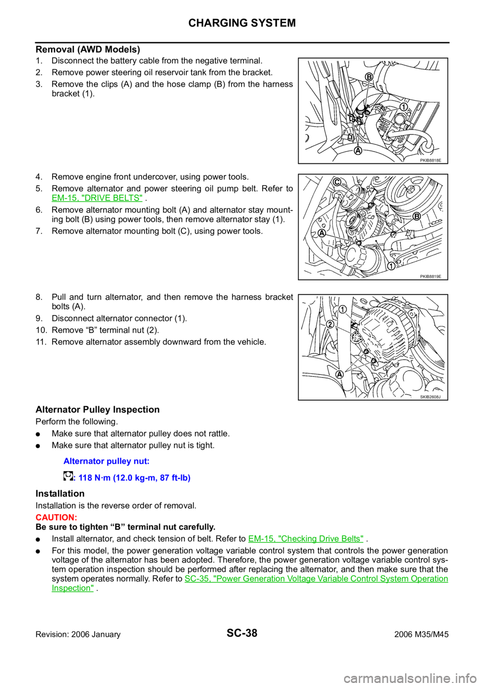
1. Disconnect the battery cable from the negative terminal.
2. Remove power steering oil reservoir tank from the bracket.
3. Remove the clips (A) and the hose clamp (B) from the harness
bracket (1).
4. Remove engine front undercover, using power tools.
5. Remove alternator and power steering oil pump belt. Refer to
EM-15, "
DRIVE BELTS" .
6. Remove alternator mounting bolt (A) and alternator stay mount-
ing bolt (B) using power tools, then remove alternator stay (1).
7. Remove alternator mounting bolt (C), using power tools.
8. Pull and turn alternator, and then remove the harness bracket
bolts (A).
9. Disconnect alternator connector (1).
10. Remove “B” terminal nut (2).
11. Remove alternator assembly downward from the vehicle.
Alternator Pulley Inspection
Perform the following.
Make sure that alternator pulley does not rattle.
Make sure that alternator pulley nut is tight.
Installation
Installation is the reverse order of removal.
CAUTION:
Be sure to tighten “B” terminal nut carefully.
Install alternator, and check tension of belt. Refer to EM-15, "Checking Drive Belts" .
For this model, the power generation voltage variable control system that controls the power generation
voltage of the alternator has been adopted. Therefore, the power generation voltage variable control sys-
tem operation inspection should be performed after replacing the alternator, and then make sure that the
system operates normally. Refer to SC-35, "
Power Generation Voltage Variable Control System Operation
Inspection" .
PKIB8818E
PKIB8819E
SKIB2608J
Alternator pulley nut:
: 118 Nꞏm (12.0 kg-m, 87 ft-lb)