2006 INFINITI M35 check engine
[x] Cancel search: check enginePage 1487 of 5621
DI-54
WARNING LAMPS
Revision: 2006 January2006 M35/M45
6. CHECK BCM INPUT SIGNAL
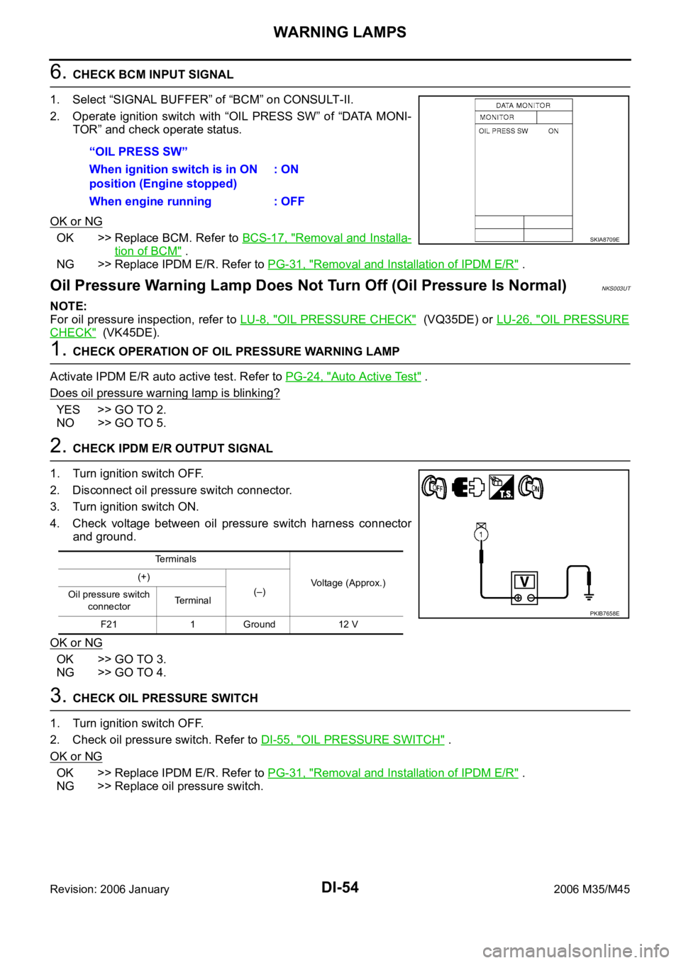
1. Select “SIGNAL BUFFER” of “BCM” on CONSULT-II.
2. Operate ignition switch with “OIL PRESS SW” of “DATA MONI-
TOR” and check operate status.
OK or NG
OK >> Replace BCM. Refer to BCS-17, "Removal and Installa-
tion of BCM" .
NG >> Replace IPDM E/R. Refer to PG-31, "
Removal and Installation of IPDM E/R" .
Oil Pressure Warning Lamp Does Not Turn Off (Oil Pressure Is Normal)NKS003UT
NOTE:
For oil pressure inspection, refer to LU-8, "
OIL PRESSURE CHECK" (VQ35DE) or LU-26, "OIL PRESSURE
CHECK" (VK45DE).
1. CHECK OPERATION OF OIL PRESSURE WARNING LAMP
Activate IPDM E/R auto active test. Refer to PG-24, "
Auto Active Test" .
Does oil pressure warning lamp is blinking?
YES >> GO TO 2.
NO >> GO TO 5.
2. CHECK IPDM E/R OUTPUT SIGNAL
1. Turn ignition switch OFF.
2. Disconnect oil pressure switch connector.
3. Turn ignition switch ON.
4. Check voltage between oil pressure switch harness connector
and ground.
OK or NG
OK >> GO TO 3.
NG >> GO TO 4.
3. CHECK OIL PRESSURE SWITCH
1. Turn ignition switch OFF.
2. Check oil pressure switch. Refer to DI-55, "
OIL PRESSURE SWITCH" .
OK or NG
OK >> Replace IPDM E/R. Refer to PG-31, "Removal and Installation of IPDM E/R" .
NG >> Replace oil pressure switch.“OIL PRESS SW”
When ignition switch is in ON
position (Engine stopped): ON
When engine running : OFF
SKIA8709E
Terminals
Voltage (Approx.) (+)
(–)
Oil pressure switch
connectorTe r m i n a l
F21 1 Ground 12 V
PKIB7658E
Page 1488 of 5621
WARNING LAMPS
DI-55
C
D
E
F
G
H
I
J
L
MA
B
DI
Revision: 2006 January2006 M35/M45
4. CHECK OIL PRESSURE SWITCH CIRCUIT
1. Turn ignition switch OFF.
2. Disconnect IPDM E/R connector.
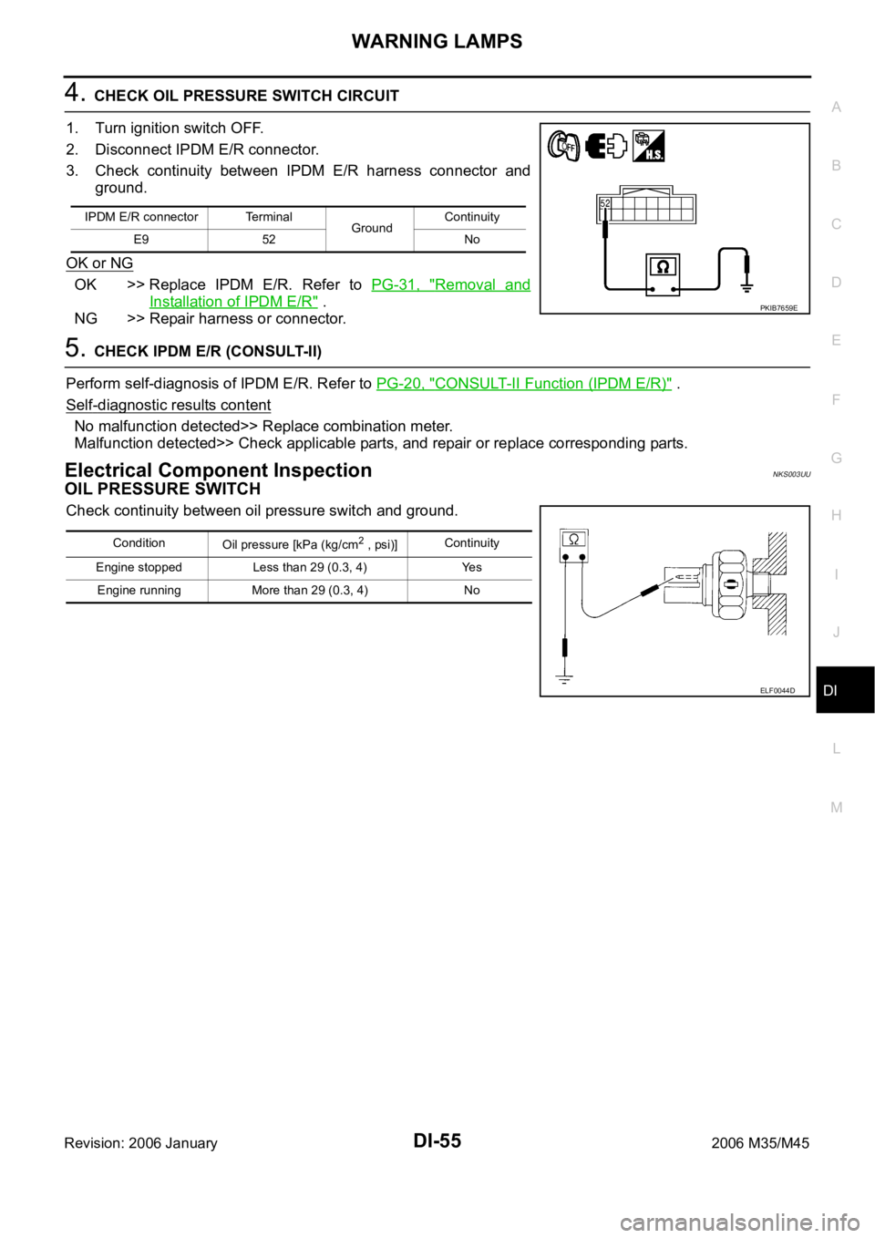
3. Check continuity between IPDM E/R harness connector and
ground.
OK or NG
OK >> Replace IPDM E/R. Refer to PG-31, "Removal and
Installation of IPDM E/R" .
NG >> Repair harness or connector.
5. CHECK IPDM E/R (CONSULT-II)
Perform self-diagnosis of IPDM E/R. Refer to PG-20, "
CONSULT-II Function (IPDM E/R)" .
Self
-diagnostic results content
No malfunction detected>> Replace combination meter.
Malfunction detected>> Check applicable parts, and repair or replace corresponding parts.
Electrical Component InspectionNKS003UU
OIL PRESSURE SWITCH
Check continuity between oil pressure switch and ground.
IPDM E/R connector Terminal
GroundContinuity
E9 52 No
PKIB7659E
Condition
Oil pressure [kPa (kg/cm2 , psi)]Continuity
Engine stopped Less than 29 (0.3, 4) Yes
Engine running More than 29 (0.3, 4) No
ELF0044D
Page 1492 of 5621
A/T INDICATOR
DI-59
C
D
E
F
G
H
I
J
L
MA
B
DI
Revision: 2006 January2006 M35/M45
A/T Indicator Is MalfunctionNKS003UX
1. CHECK SEGMENTS OF A/T INDICATOR
Perform self-diagnosis mode of combination meter. Refer to DI-17, "
OPERATION PROCEDURE" .
Are all segments displayed?
YES >> GO TO 2.
NO >> Replace combination meter.
2. CHECK UNIFIED METER AND A/C AMP. (CONSULT-II)
Perform self-diagnosis of unified meter and A/C amp. Refer to DI-31, "
CONSULT-II Function (METER A/C
AMP)" .
Self
-diagnostic results content
No malfunction detected>> GO TO 3.
Malfunction detected>> Check applicable parts, and repair or replace corresponding parts.
3. CHECK UNIFIED METER AND A/C AMP. INPUT SIGNAL
1. Connect CONSULT-II and start engine.
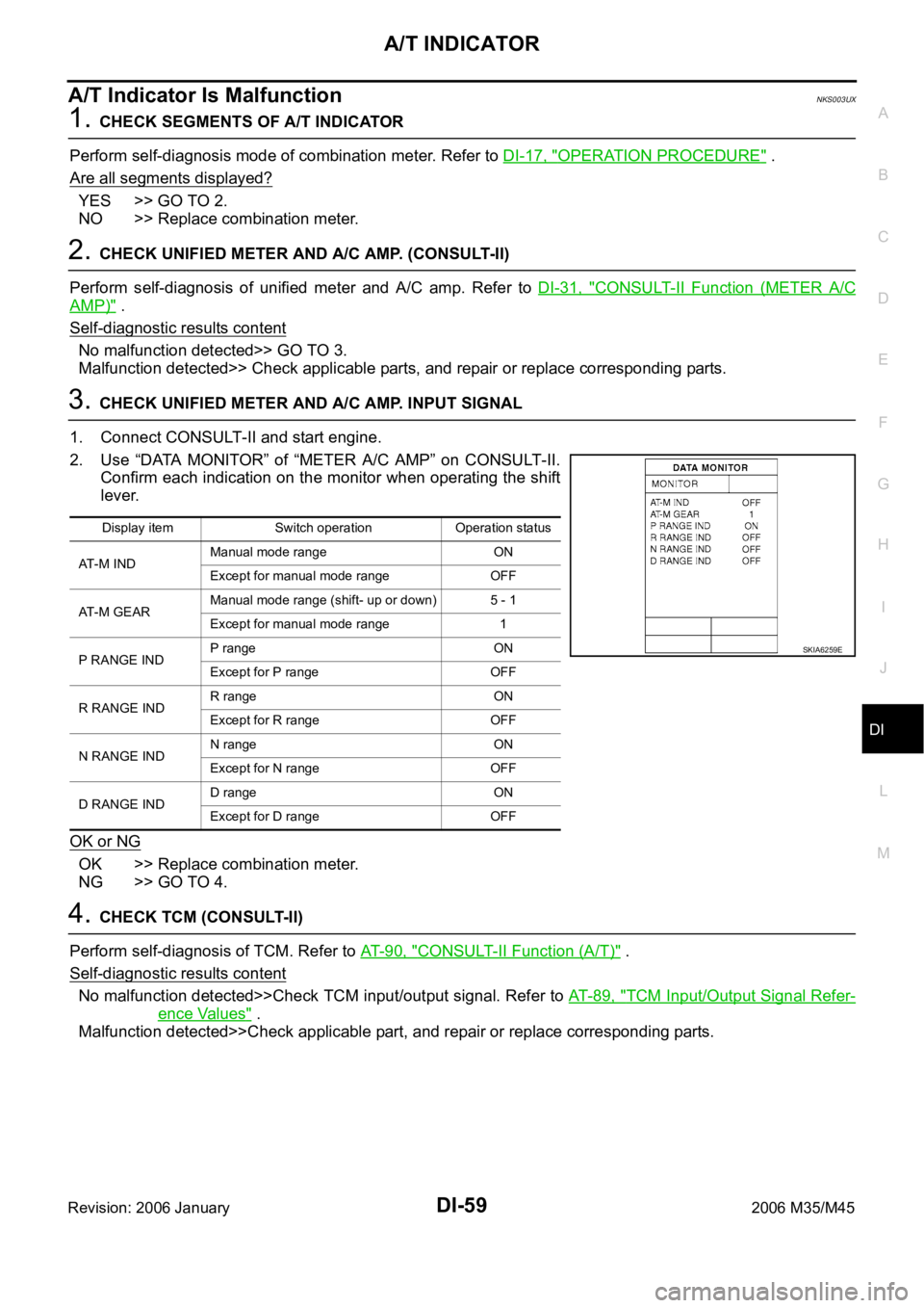
2. Use “DATA MONITOR” of “METER A/C AMP” on CONSULT-II.
Confirm each indication on the monitor when operating the shift
lever.
OK or NG
OK >> Replace combination meter.
NG >> GO TO 4.
4. CHECK TCM (CONSULT-II)
Perform self-diagnosis of TCM. Refer to AT- 9 0 , "
CONSULT-II Function (A/T)" .
Self-diagnostic results content
No malfunction detected>>Check TCM input/output signal. Refer to AT- 8 9 , "TCM Input/Output Signal Refer-
ence Values" .
Malfunction detected>>Check applicable part, and repair or replace corresponding parts.
Display item Switch operation Operation status
AT-M INDManual mode range ON
Except for manual mode range OFF
AT-M GEARManual mode range (shift- up or down) 5 - 1
Except for manual mode range 1
P RANGE INDP range ON
Except for P range OFF
R RANGE INDR range ON
Except for R range OFF
N RANGE INDN range ON
Except for N range OFF
D RANGE INDD range ON
Except for D range OFF
SKIA6259E
Page 1514 of 5621
LANE DEPARTURE WARNING SYSTEM
DI-81
C
D
E
F
G
H
I
J
L
MA
B
DI
Revision: 2006 January2006 M35/M45
Camera Aiming AdjustmentNKS003VI
OUTLINE
Adjust the camera aiming every time the LDW camera unit is removed or installed.
CAUTION:
Place the vehicle on the level ground when the camera aiming adjustment is operated.
Follow the CONSULT-II when adjusting the camera aiming. (Camera aiming adjustment cannot be
operated without CONSULT-II.)
PREPARATION
Keep all tires inflated to correct pressures. Adjust the tire pressure to the specified pressure value.
There is no-load in vehicle. Check if coolant, engine oil are filled up to correct level and fuel tank is full.
Shift the gear into “P” position and release the parking brake.
Clean the windshield.
NOTE:
Do not place anything reflective on the upper surface of instrument panel.
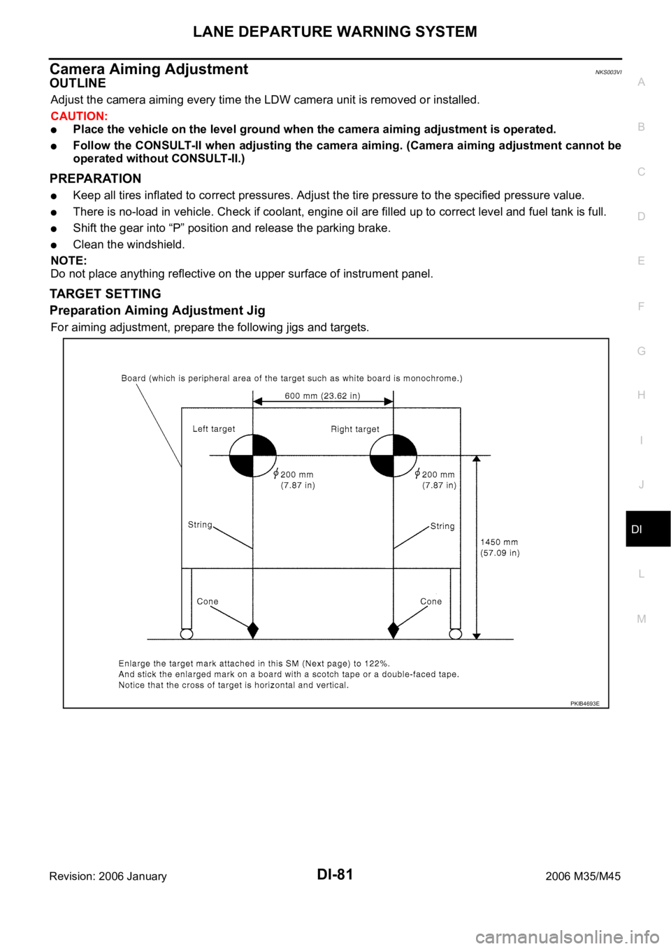
TARGET SETTING
Preparation Aiming Adjustment Jig
For aiming adjustment, prepare the following jigs and targets.
PKIB4693E
Page 1517 of 5621
DI-84
LANE DEPARTURE WARNING SYSTEM
Revision: 2006 January2006 M35/M45
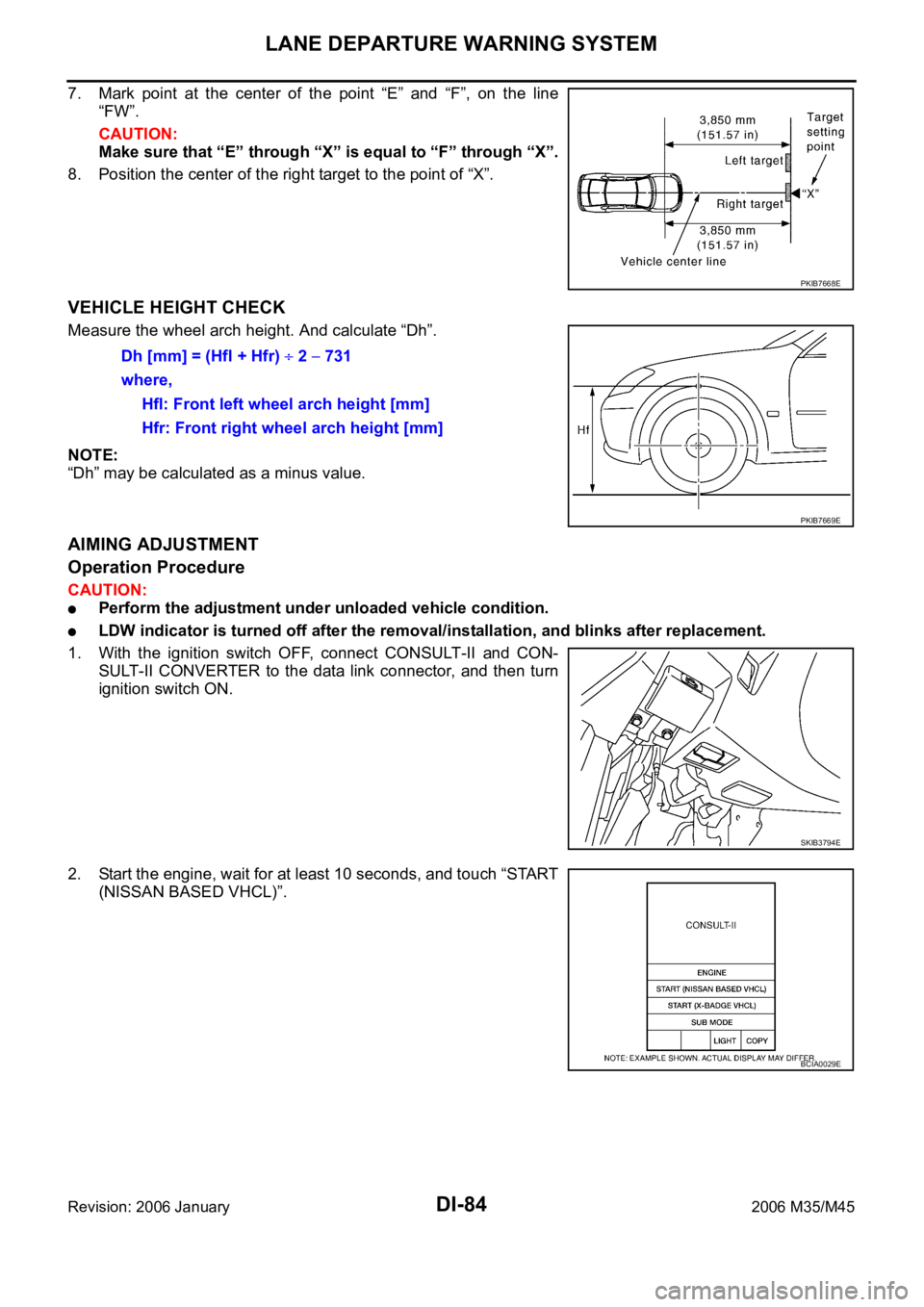
7. Mark point at the center of the point “E” and “F”, on the line
“FW”.
CAUTION:
Make sure that “E” through “X” is equal to “F” through “X”.
8. Position the center of the right target to the point of “X”.
VEHICLE HEIGHT CHECK
Measure the wheel arch height. And calculate “Dh”.
NOTE:
“Dh” may be calculated as a minus value.
AIMING ADJUSTMENT
Operation Procedure
CAUTION:
Perform the adjustment under unloaded vehicle condition.
LDW indicator is turned off after the removal/installation, and blinks after replacement.
1. With the ignition switch OFF, connect CONSULT-II and CON-
SULT-II CONVERTER to the data link connector, and then turn
ignition switch ON.
2. Start the engine, wait for at least 10 seconds, and touch “START
(NISSAN BASED VHCL)”.
PKIB7668E
Dh [mm] = (Hfl + Hfr) 2 731
where,
Hfl: Front left wheel arch height [mm]
Hfr: Front right wheel arch height [mm]
PKIB7669E
SKIB3794E
BCIA0029E
Page 1544 of 5621
EC-1
ENGINE CONTROL SYSTEM
B ENGINE
CONTENTS
C
D
E
F
G
H
I
J
K
L
M
SECTION EC
A
EC
Revision: 2006 January2006 M35/M45
ENGINE CONTROL SYSTEM
VQ35DE
INDEX FOR DTC ...................................................... 16
DTC No. Index ....................................................... 16
Alphabetical Index .................................................. 20
PRECAUTIONS ........................................................ 24
Precautions for Supplemental Restraint System
(SRS) “AIR BAG” and “SEAT BELT PRE-TEN-
SIONER” ................................................................ 24
Precautions for Procedures without Cowl Top Cover ... 24
On Board Diagnostic (OBD) System of Engine and
A/T .......................................................................... 24
Precaution .............................................................. 25
PREPARATION ......................................................... 28
Special Service Tools ............................................. 28
Commercial Service Tools ...................................... 29
ENGINE CONTROL SYSTEM .................................. 30
System Diagram ..................................................... 30
Multiport Fuel Injection (MFI) System .................... 31
Electronic Ignition (EI) System ............................... 33
Fuel Cut Control (At No Load and High Engine
Speed) .................................................................... 34
AIR CONDITIONING CUT CONTROL ..................... 35
Input/Output Signal Chart ....................................... 35
System Description ................................................ 35
AUTOMATIC SPEED CONTROL DEVICE (ASCD) ... 36
System Description ................................................ 36
Component Description .......................................... 37
CAN COMMUNICATION .......................................... 38
System Description ................................................ 38
EVAPORATIVE EMISSION SYSTEM ....................... 39
Description ............................................................. 39
Component Inspection ........................................... 42
Removal and Installation ........................................ 43
How to Detect Fuel Vapor Leakage ....................... 43
ON BOARD REFUELING VAPOR RECOVERY
(ORVR) ...................................................................... 46
System Description ................................................ 46
Diagnostic Procedure ............................................. 47
Component Inspection ........................................... 49POSITIVE CRANKCASE VENTILATION ................. 51
Description .............................................................. 51
Component Inspection ............................................ 51
IVIS (INFINITI VEHICLE IMMOBILIZER SYSTEM-
NATS) ........................................................................ 53
Description .............................................................. 53
ON BOARD DIAGNOSTIC (OBD) SYSTEM ............ 54
Introduction ..................................................
........... 54
Two Trip Detection Logic ........................................ 54
Emission-Related Diagnostic Information ............... 55
Malfunction Indicator Lamp (MIL) ........................... 69
OBD System Operation Chart ................................ 72
BASIC SERVICE PROCEDURE ............................... 77
Basic Inspection ..................................................... 77
Idle Speed and Ignition Timing Check .................... 82
Idle Mixture Ratio Adjustment ................................. 84
VIN Registration ..................................................... 95
Accelerator Pedal Released Position Learning ...... 95
Throttle Valve Closed Position Learning ................. 95
Idle Air Volume Learning ........................................ 96
Fuel Pressure Check .............................................. 98
TROUBLE DIAGNOSIS ..........................................100
Trouble Diagnosis Introduction .............................100
DTC Inspection Priority Chart ...............................106
Fail-Safe Chart .....................................................108
Symptom Matrix Chart ..........................................109
Engine Control Component Parts Location ..........113
Vacuum Hose Drawing .........................................121
Circuit Diagram .....................................................122
ECM Harness Connector Terminal Layout ...........124
ECM Terminals and Reference Value ...................124
CONSULT-II Function (ENGINE) ..........................133
Generic Scan Tool (GST) Function .......................146
CONSULT-II Reference Value in Data Monitor .....149
Major Sensor Reference Graph in Data Monitor
Mode .....................................................................153
TROUBLE DIAGNOSIS - SPECIFICATION VALUE .155
Description ............................................................155
Testing Condition ..................................................155
Page 1548 of 5621

EC-5
C
D
E
F
G
H
I
J
K
L
M
ECA
Revision: 2006 January2006 M35/M45 DTC Confirmation Procedure ...............................451
Wiring Diagram ....................................................452
Diagnostic Procedure ...........................................453
Component Inspection .........................................457
DTC P0455 EVAP CONTROL SYSTEM ................458
On Board Diagnosis Logic ...................................458
DTC Confirmation Procedure ...............................459
Diagnostic Procedure ...........................................460
DTC P0456 EVAP CONTROL SYSTEM ................466
On Board Diagnosis Logic ...................................466
DTC Confirmation Procedure ...............................467
Overall Function Check ........................................468
Diagnostic Procedure ...........................................469
DTC P0460 FUEL LEVEL SENSOR ......................475
Component Description ........................................475
On Board Diagnosis Logic ...................................475
DTC Confirmation Procedure ...............................475
Diagnostic Procedure ...........................................476
Removal and Installation ......................................476
DTC P0461 FUEL LEVEL SENSOR ......................477
Component Description ........................................477
On Board Diagnosis Logic ...................................477
Overall Function Check ........................................477
Diagnostic Procedure ...........................................478
Removal and Installation ......................................478
DTC P0462, P0463 FUEL LEVEL SENSOR CIR-
CUIT ........................................................................479
Component Description ........................................479
On Board Diagnosis Logic ...................................479
DTC Confirmation Procedure ...............................479
Diagnostic Procedure ...........................................480
Removal and Installation ......................................480
DTC P0500 VSS .....................................................481
Description ...........................................................481
On Board Diagnosis Logic ...................................481
DTC Confirmation Procedure ...............................481
Overall Function Check ........................................482
Diagnostic Procedure ...........................................482
DTC P0506 ISC SYSTEM .......................................483
Description ...........................................................483
On Board Diagnosis Logic ...................................483
DTC Confirmation Procedure ...............................483
Diagnostic Procedure ...........................................484
DTC P0507 ISC SYSTEM .......................................485
Description ...........................................................485
On Board Diagnosis Logic ...................................485
DTC Confirmation Procedure ..............................
.485
Diagnostic Procedure ...........................................486
DTC P0550 PSP SENSOR .....................................487
Component Description ........................................487
CONSULT-II Reference Value in Data Monitor Mode
.487
On Board Diagnosis Logic ...................................487
DTC Confirmation Procedure ...............................487
Wiring Diagram ....................................................488
Diagnostic Procedure ...........................................489
Component Inspection .........................................491
Removal and Installation ......................................491DTC P0603 ECM POWER SUPPLY .......................492
Component Description ........................................492
On Board Diagnosis Logic ....................................492
DTC Confirmation Procedure ...............................492
Wiring Diagram .....................................................493
Diagnostic Procedure ...........................................494
DTC P0605 ECM .....................................................496
Component Description ........................................496
On Board Diagnosis Logic ....................................496
DTC Confirmation Procedure ...............................496
Diagnostic Procedure ...........................................497
DTC P0643 SENSOR POWER SUPPLY ................499
On Board Diagnosis Logic ....................................499
DTC Confirmation Procedure ...............................499
Wiring Diagram .....................................................500
Diagnostic Procedure ...........................................502
DTC P0850 PNP SWITCH ......................................504
Component Description ........................................504
CONSULT-II Reference Value in Data Monitor Mode
.504
On Board Diagnosis Logic ....................................504
DTC Confirmation Procedure ...............................504
Overall Function Check ........................................505
Wiring Diagram .....................................................506
Diagnostic Procedure ...........................................507
DTC P1148, P1168 CLOSED LOOP CONTROL ....509
On Board Diagnosis Logic ....................................509
DTC P1211 TCS CONTROL UNIT ..........................510
Description ............................................................510
On Board Diagnosis Logic ....................................510
DTC Confirmation Procedure ...............................510
Diagnostic Procedure ...........................................510
DTC P1212 TCS COMMUNICATION LINE ............511
Description ............................................................511
On Board Diagnosis Logic ....................................511
DTC Confirmation Procedure ...............................511
Diagnostic Procedure ...........................................511
DTC P1217 ENGINE OVER TEMPERATURE .......
.512
Description ............................................................512
CONSULT-II Reference Value in Data Monitor Mode
.513
On Board Diagnosis Logic ....................................513
Overall Function Check ........................................513
Wiring Diagram .....................................................515
Diagnostic Procedure ...........................................517
Main 12 Causes of Overheating ...........................522
Component Inspection ..........................................524
DTC P1220 FUEL PUMP CONTROL MODULE
(FPCM) ....................................................................525
Description ............................................................525
CONSULT-II Reference Value in Data Monitor Mode
.525
On Board Diagnosis Logic ....................................525
DTC Confirmation Procedure ...............................526
Wiring Diagram .....................................................527
Diagnostic Procedure ...........................................528
Component Inspection ..........................................532
DTC P1225 TP SENSOR ........................................533
Component Description ........................................533
Page 1551 of 5621

EC-8Revision: 2006 January2006 M35/M45 Wiring Diagram .....................................................708
Diagnostic Procedure ...........................................709
Component Inspection ..........................................713
ASCD INDICATOR .................................................
.714
Component Description ........................................714
CONSULT-II Reference Value in Data Monitor Mode
.714
Wiring Diagram .....................................................715
Diagnostic Procedure ...........................................716
SNOW MODE SWITCH ...........................................717
Description ............................................................717
CONSULT-II Reference Value in the Data Monitor
Mode .....................................................................717
Wiring Diagram .....................................................718
Diagnostic Procedure ...........................................719
Component Inspection ..........................................721
MIL AND DATA LINK CONNECTOR ......................722
Wiring Diagram .....................................................722
SERVICE DATA AND SPECIFICATIONS (SDS) ....724
Fuel Pressure .......................................................724
Idle Speed and Ignition Timing .............................724
Calculated Load Value ..........................................724
Mass Air Flow Sensor ...........................................724
Intake Air Temperature Sensor .............................724
Engine Coolant Temperature Sensor ...................724
Fuel Tank Temperature Sensor ............................724
Crankshaft Position Sensor (POS) .......................724
Camshaft Position Sensor (PHASE) ....................724
A/F Sensor 1 Heater ............................................ .724
Heated Oxygen Sensor 2 Heater .........................725
Throttle Control Motor ...........................................725
Fuel Injector ..........................................................725
Fuel Pump ............................................................725
VK45DE
INDEX FOR DTC .....................................................726
DTC No. Index ......................................................726
Alphabetical Index ................................................730
PRECAUTIONS .......................................................734
Precautions for Supplemental Restraint System
(SRS) “AIR BAG” and “SEAT BELT PRE-TEN-
SIONER” ...............................................................734
Precautions for Procedures without Cowl Top Cover .734
On Board Diagnostic (OBD) System of Engine and
A/T ........................................................................734
Precaution ............................................................735
PREPARATION .......................................................738
Special Service Tools ...........................................738
Commercial Service Tools ....................................739
ENGINE CONTROL SYSTEM ................................740
System Diagram ...................................................740
Multiport Fuel Injection (MFI) System ...................741
Electronic Ignition (EI) System .............................743
Fuel Cut Control (At No Load and High Engine
Speed) ..................................................................744
AIR CONDITIONING CUT CONTROL ....................745
Input/Output Signal Chart .....................................745
System Description ...............................................745AUTOMATIC SPEED CONTROL DEVICE (ASCD) .746
System Description ...............................................746
Component Description ........................................747
CAN COMMUNICATION .........................................748
System Description ...............................................748
EVAPORATIVE EMISSION SYSTEM .....................749
Description ............................................................749
Component Inspection ..........................................752
Removal and Installation .......................................753
How to Detect Fuel Vapor Leakage ......................753
ON BOARD REFUELING VAPOR RECOVERY
(ORVR) ....................................................................756
System Description ...............................................756
Diagnostic Procedure ............................................757
Component Inspection ..........................................759
POSITIVE CRANKCASE VENTILATION ................761
Description ............................................................761
Component Inspection ..........................................761
IVIS (INFINITI VEHICLE IMMOBILIZER SYSTEM-
NATS) ......................................................................763
Description ............................................................763
ON BOARD DIAGNOSTIC (OBD) SYSTEM ...........764
Introduction ..........................................................
.764
Two Trip Detection Logic .......................................764
Emission-Related Diagnostic Information .............765
Malfunction Indicator Lamp (MIL) .........................780
OBD System Operation Chart ...............................782
BASIC SERVICE PROCEDURE .............................788
Basic Inspection ....................................................788
Idle Speed and Ignition Timing Check ..................793
Idle Mixture Ratio Adjustment ...............................795
VIN Registration ....................................................806
Accelerator Pedal Released Position Learning .....806
Throttle Valve Closed Position Learning ...............806
Idle Air Volume Learning .......................................807
Fuel Pressure Check ............................................809
TROUBLE DIAGNOSIS ..........................................811
Trouble Diagnosis Introduction .............................811
DTC Inspection Priority Chart ...............................817
Fail-Safe Chart ......................................................819
Symptom Matrix Chart ..........................................820
Engine Control Component Parts Location ...........824
Vacuum Hose Drawing .........................................833
Circuit Diagram .....................................................834
ECM Harness Connector Terminal Layout ............836
ECM Terminals and Reference Value ...................836
CONSULT-II Function (ENGINE) ..........................846
Generic Scan Tool (GST) Function .......................859
CONSULT-II Reference Value in Data Monitor .....862
Major Sensor Reference Graph in Data Monitor
Mode .....................................................................866
TROUBLE DIAGNOSIS - SPECIFICATION VALUE .868
Description ............................................................868
Testing Condition ..................................................868
Inspection Procedure ...........................................
.868
Diagnostic Procedure ............................................869
TROUBLE DIAGNOSIS FOR INTERMITTENT INCI-